Transcription
Dell PowerVault LTO Tape User's GuideUser's Guide
Note!Before using this information and the product it supports, be sure to read the general information under Notices in the DellPowerVault LTO Tape Drive User's Guide.NOTE indicates important information that helps you make better use of your system.NOTICE indicates either potential damage to hardware or loss of data and tells you how to avoid the problem.CAUTION indicates a potential for property damage, personal injury, or death.Information in this document is subject to change without notice. 2012, 2015 Dell Inc. All rights reserved. International Business Machines Corporation, 2012, 2015. All rights reserved.Trademarks used in this text: Dell, the DELL logo, and PowerVault, are trademarks of Dell Inc. Microsoft and Windowsare registered trademarks of Microsoft Corporation.Other trademarks and trade names may be used in this document to refer to either the entities claiming the marksand names or their products. Dell Inc. disclaims any proprietary interest in trademarks and trade names other thanits own.v Internal Drive Model Numbers: LTO Ultrium 7-H, LTO Ultrium 6-H, LTO Ultrium 5-H, LTO Ultrium 4-H, LTOUltrium 3-Hv External Drive Model Numbers: CSEH 001, LTO4-EH1, LTO3-EH1v Rack Mount Model Number: 2U Storage Rack AInitial release: November 2015
ContentsFigures . . . . . . . . . . . . . . . vTables . . . . . . . . . . . . . . . viiChapter 1. Introduction . . . . . . . 1-1Overview . . . . . .Encryption . . . . .Specifications and FeaturesTape Backup Software .Front Panel . . . . .Rear Panel . . . . .Chapter 2. Setting Up the Tape DrivePre-installed Internal Drives . . . . . .Installing Internal Drives . . . . . . .Installing the Internal Drive - Step-By-StepInstructions . . . . . . . . . . .Installing External and Rack Mount Drives .Installing the External Drive - Step-By-StepInstructions . . . . . . . . . . .Verifying Drive Operation . . . . . .Loading Device Drivers . . . . . . .Ethernet Service Port Procedures . . . .Chapter 3. Using the Tape DriveOperating the Drive . . . . . . .Loading, Unloading, and Write-ProtectingCartridges . . . . . . . . . .Caring for Tape Cartridges . . . . .Cleaning the Tape Mechanism . . . .1-11-21-31-41-41-62-1. 2-1. 2-1. 2-1. 2-5.2-52-72-72-8. . . 3-1Selecting a Diagnostic or Maintenance Function .General Guidelines . . . . . . . . . .Methods of Receiving Errors and Messages . .Descriptions and Corrective Actions . . . .Drive Status . . . . . . . . . . . .Drive Maintenance . . . . . . . . . .Fixing SAS Connectivity Problems . . . . .Resolving Media-Related Problems . . . . .Removing an Internal SAS Tape Drive . . . .TapeAlert . . . . . . . . . . . . .Recovering a Tape Cartridge . . . . . . . 5-1. 5-9. 5-10. 5-11. 5-14. 5-15. 5-16. 5-17. 5-17. 5-18. 5-21Chapter 6. Specifications . . . . . . 6-1General Specifications.Internal Drive . .External Drive . .Rack Mount Drive .6-16-16-26-3Chapter 7. Getting Help . . . . . . . 7-1Technical Assistance . . . . . . . . .Dell Enterprise Training and Certification . .Problems with Your Order . . . . . . .Product Information . . . . . . . . .Returning Items for Warranty Repair or CreditBefore You Call . . . . . . . . . . .7-17-37-37-37-37-3. 3-1Chapter 8. Contacting Dell . . . . . . 8-1. 3-2. 3-5. 3-7Appendix. Regulatory Information . . A-1Glossary . . . . . . . . . . . . . B-1Chapter 4. Using the Tape BackupSoftware. . . . . . . . . . . . . . 4-1Chapter 5. TroubleshootingIndex . . . . . . . . . . . . . . . X-1. . . . . 5-1Obtaining Drivers and Firmware Upgrades. 5-1iii
ivDell PowerVault LTO Tape Drive User's Guide
.2-5.PowerVault Internal Model . . . . .PowerVault External Model . . . . .PowerVault Rack Mount Model . . . .Front Panel. . . . . . . . . . .Rear Panel of Internal SAS Tape DriveRear Panel of External SAS Tape DriveRear Panel of the Rack Mount Tape DriveAir Intake Area . . . . . . . . .Install the Drive . . . . . . . . .Mounting Holes on Tape Drive . . . .Attaching SAS Cable . . . . . . .Secure the Drive . . . . . . . . -2.3-3.3-4.3-5.3-6.5-1.5-2.5-3.Connecting the SAS cable . . . . .Connecting two SAS Hosts to one TapeDrive. . . . . . . . . . . .Turning on the External Drive . . .Turning on the Rack Mount DriveResetting the Drive . . . . . . .LTO Ultrium Data Cartridge . . . .Loading . . . . . . . . . . .Setting the Write-Protect Switch . . .Drive Status page . . . . . . .Drive Status page - details . . . .Drive Maintenance page . . . . . 2-6. 2-7. 3-13-1. 3-2. 3-3. 3-4. 3-5. 5-15. 5-15. 5-16.v
viDell PowerVault LTO Tape Drive User's Guide
Tables1-1.1-2.3-1.3-2.5-1.5-2.LTO Generation Specifications . . . . . 1-3SCD, Ready/Activity LED, and Fault LEDDescriptions . . . . . . . . . . . 1-5Supported Functions of Compatible MediaTypes. . . . . . . . . . . . . . 3-2Environmental Specifications . . . . . . 3-6Diagnostic and Maintenance Function Codesand Descriptions . . . . . . . . . . 5-2General Troubleshooting . . . . . . . 5-105-3.5-4.5-5.6-1.6-2.6-3.6-4.7-1.Methods of Receiving Errors and MessagesDescriptions and Corrective ActionsTapeAlert Flags and DescriptionsGeneral specifications . . . . . . .Internal Drive specifications . . . . .External Drive specifications . . . . .Rack Mount drive specifications . . . .Diagnostics Checklist . . . . . . .5-115-115-18. 6-1. 6-1. 6-2. 6-3. 7-4vii
viiiDell PowerVault LTO Tape Drive User's Guide
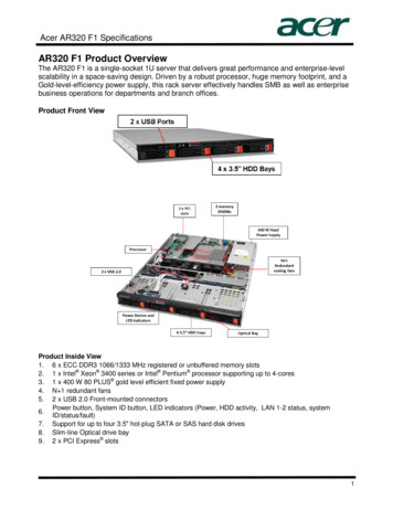
Chapter 1. Introductionv “Overview”– “Serial Attached SCSI (SAS) Interface” on page 1-2v “Encryption” on page 1-2v “Specifications and Features” on page 1-3v “Tape Backup Software” on page 1-4v “Front Panel” on page 1-4v “Rear Panel” on page 1-6OverviewThe LTO PowerVault tape drive is a high-performance, high-capacity data-storagedevice that is designed to back up and restore data and archive and retrieve filesin an Open Systems environment. The drive can be integrated into a system(internal model) or can be provided as a separately packaged desktop unit(external model). There are seven generations of the Dell PowerVault tape drives inthe LTO series of products.a80hd004Figure 1-1 shows the internal model of the tape drive. Figure 1-2 on page 1-2shows the separately purchased external model of the tape drive. Figure 1-3 onpage 1-2 shows the rack mount model.Figure 1-1. PowerVault Internal Model1-1
a80hd001a77ug279Figure 1-2. PowerVault External ModelFigure 1-3. PowerVault Rack Mount ModelSerial Attached SCSI (SAS) InterfaceA drive with a SAS (Serial Attached SCSI) interface can be linked directly tocontrollers. The SAS interface offers the following advantages over the traditionalSCSI interface:v SAS enables multiple devices (up to 128) of different sizes and types to beconnected simultaneously with thinner and longer cables.v Its full-duplex signal transmission supports up to 6.0 Gb/s.v SAS drives can be hot-plugged.EncryptionThe Tape Drive has Application Managed Encryption (AME) with T10 encryptionmethods. You must have an application that supports encryption to use the drive'sencryption capability. Data encryption is supported by LTO Ultrium 4 and laterdata cartridges only. For more details, consult your application supportdocumentation.1-2Dell PowerVault LTO Tape Drive User's Guide
Specifications and FeaturesSpecificationsTable 1-1. LTO Generation SpecificationsPowerVault 3-80NativeCapacity6000 GB2500 GB1500 GB800 GB400 GB2.5:1CompressedCapacity15000 GB6250 GBNANANA2:1CompressedCapacity12000 GB5000 GB3000 GB1600 GB800 GBMaximumNative DataTransfer300 MB/s160 MB/s140 MB/s120 MB/s80 MB/sCompressedMaximumDataTransfer*750 MB/s400 MB/s280 MB/s240 MB/s160 MB/sMediaXPartitioning**XXNANAData SafeMode**XXXNANAEncryptionStatus LEDXXXNANA* Assumes compression. The capacity and transfer rate you realize in practicedepends on the data set, which affects the actual compression ratio. LTO7 andLTO6 support 2.5:1 compression. LTO5-140 and below support 2:1 compression.** This feature must be supported by your tape backup software.FeaturesThe tape drive has the following features:v Built-in read-after-write verification for a high level of data integrityvvvvvBurst data transfer rate of 600 MB per second512 MB of read/write cache memoryIntelligent LTO-DC dual-mode compression algorithmFailsafe leader capture mechanism with pin pick error recoveryReads cartridge memory in LTO cartridgesv TapeAlert support for improved diagnostic and troubleshootingv Two 6 Gb Serial Attached SCSI interfacev Speed matching (The drive can slow down to match the system data rate.)v Sleep mode for energy conservationv Backward read and write compatibility dependent on generationChapter 1. Introduction1-3
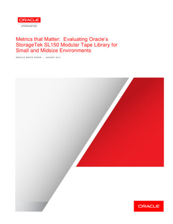
v Compatible with all cartridges dependent on generation that bears the officialUltrium LTO logo. See Table 3-1 on page 3-2 for more information.v Will interchange tapes with other LTO tape drives that bear the official UltriumLTO logov Support for WORM (Write Once Read Many) using WORM mediav Data encryption capability using LTO Ultrium 4, 5 and 6 mediav Ethernet interface for transferring drive firmware and dumps only (not an iSCSIinterface)v Diagnostics of the drive over the ethernet service port (not an iSCSI interface)Tape Backup SoftwareYou need backup software that supports the Dell PowerVault tape drive. As ageneral rule, native backup applications (such as NTBackup and tar) do notprovide the required data streaming rate to get the full performance of your tapedrive. It is recommend that you use a backup application that provides bettermemory management as well as other useful features, such as TapeAlert. For thelatest supported software versions, go to the Dell support website athttp://www.Dell.com/support or visit the support site of your backup softwarevendor.Front Panel12635a80hd0034Figure 1-4. Front Panel 1 Eject button 4 Single-character display (SCD) 2 Ready/Activity LED 5 Single dot 3 Fault LED 6 Encryption Status LED1. Eject button. The eject button enables you to perform several functions. Thesefunctions are described in detail in Chapter 3, “Using the Tape Drive,” on page3-1.2. Ready/Activity LED. The front panel of your Dell PowerVault LTO tape drivehas a green Ready/Activity LED providing information about the state of thetape drive. The LED can be solid on or flashing when lit. See Table 1-2 on page1-5 for more descriptions.1-4Dell PowerVault LTO Tape Drive User's Guide
3. Fault LED. The front panel of your Dell PowerVault LTO tape drive has anamber fault LED indicating the drive has encountered an error, is not in anormal operational status, or needs cleaning. See Table 1-2 for more detaileddescription.4. Single-character display (SCD). This LED presents a single-character code fordiagnostic/maintenance functions, error conditions, and informationalmessages.5. Single dot. This single-character display is blank during normal operation.When a single dot illuminates and flashes on the display, the drive has createda dump of vital technical data to drive memory.6. Encryption status LED. This white LED indicates all data (except for the labelinformation) on the cartridge is encrypted. (LTO Ultrium 5 and abovecartridges only.)Table 1-2. SCD, Ready/Activity LED, and Fault LED DescriptionsCondition ofgreenReady/Activity LEDConditionof amberFault LEDConditionof whiteencryption Condition ofCondition ofLEDthe SCD Panel the SCD DotOffOffOffOn SolidOffOffOffOff orCMeaning of LEDs and SCD Panel andSCD DotOffThe tape drive has no power or ispowered off.OffThe tape drive is powered on or (if asolid C displays in the singlecharacter display) needs cleaning.Note: If a cartridge is loaded, thewhite Encryption status light is onwhen all the data on the cartridge isencrypted (excluding the label). LTOUltrium 5 and above cartridges only.Flashing once Offper secondOn or OffOffOffThe tape drive is reading from thetape, writing to the tape, rewinding thetape, locating data on the tape, loadingthe tape, or unloading the tape. TheEncryption LED will be On if all thedata on the cartridge is encryptedduring these drive operations. TheReady/Activity LED also flashes greenif the tape drive contains a cartridgeduring the power on cycle. In this case,the drive completes POST and slowlyrewinds the tape (this process may takeapproximately 13 minutes). TheReady/Activity LED stops blinkingwhen the drive completes the recoveryand is ready for a read or writeoperation. To eject the cartridge, pressthe unload button.Note: The white Encryption statuslight is on when all the data on thecartridge is encrypted (excluding thelabel). LTO Ultrium 5 and abovecartridges only.OffOffOn SolidOn/OffThe tape drive is in maintenance modeor is displaying an error code on theSCD in maintenance mode option 9.On/SolidChapter 1. Introduction1-5
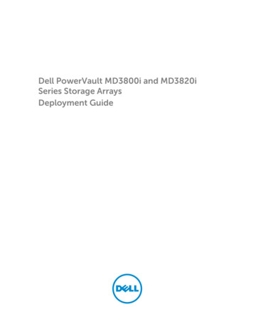
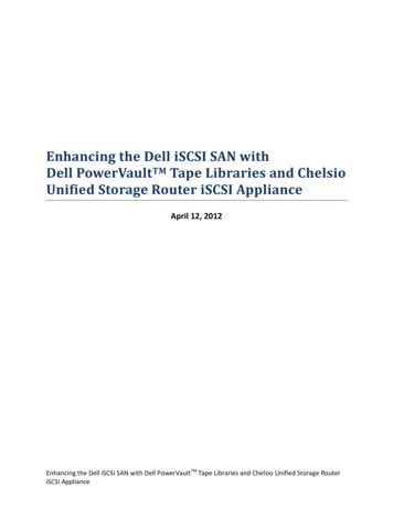
Table 1-2. SCD, Ready/Activity LED, and Fault LED Descriptions (continued)Condition ofgreenReady/Activity LEDConditionof amberFault LEDConditionof whiteencryption Condition ofCondition ofLEDthe SCD Panel the SCD DotOffOn SolidOffFlashing onceper secondOn/OffExecuting the selected option while inmaintenance mode.OffFlashingonce persecondOffOn SolidOffAn error occurred and the tape driveor media may require service or drivemay require cleaning.Meaning of LEDs and SCD Panel andSCD DotNote the code on the single characterdisplay, and then go to the error codetable in the troubleshooting section todetermine the meaning of the errorcodes.If a C appears on the SCD, acleaning cartridge must be loaded.OffFlashingtwice persecondOffOffOffThe drive is updating firmware.OffFlashingonce every2 secondsOffOffOffThe drive detected an error and isperforming a firmware recovery. It willreset automatically.2143Figure 1-5. Rear Panel of Internal SAS Tape Drive1-6 1 SAS connector 2 Ethernet - not iSCSI - for 4 transferring firmwareand dumps onlyDell PowerVault LTO Tape Drive User's Guide 3 Library interfaceLED controls for library drive sleda80hh095Rear Panel
12a80hh01234Figure 1-6. Rear Panel of External SAS Tape Drive 1 Power connector 3 SAS connectors 2 Fan enclosure 4 Ethernet - not iSCSI - for transferringfirmware and dumps only3344a80hh08912Figure 1-7. Rear Panel of the Rack Mount Tape Drive 1 Power connector 3 SAS connectors 2 Fan enclosure 4 Ethernet - not iSCSI - for transferringfirmware and dumps onlyChapter 1. Introduction1-7
1-8Dell PowerVault LTO Tape Drive User's Guide
Chapter 2. Setting Up the Tape Drivev “Pre-installed Internal Drives”v “Installing Internal Drives”– “Installing the Internal Drive - Step-By-Step Instructions”v “Installing External and Rack Mount Drives” on page 2-5– “Installing the External Drive - Step-By-Step Instructions” on page 2-5v “Verifying Drive Operation” on page 2-7v “Loading Device Drivers” on page 2-7v “Ethernet Service Port Procedures” on page 2-8Pre-installed Internal DrivesDell performs the installation and setup of internal tape drives that are shipped aspart of a system. If tape backup software is included in your system, refer to theinstallation instructions included with the software.For the latest supported software versions, go to the Dell support websitehttp://www.Dell.com/support or visit the support site of your backup softwarevendor.Installing Internal DrivesIf your internal tape drive is not pre-installed, the installation instructions aredescribed in the following sections:Installing the Drive — PrerequisitesThe Dell PowerVault tape drive is a 6 Gb SAS device with a burst transfer rate of600 MB per second. It is recommended that you use a dedicated SAS host busadapter for this tape drive.Mounting BayYou need one industry-standard, 5 1/4 inch, half-height bay in which to install thePowerVault tape drive. The only supported mounting configurations arehorizontally with the base of the drive parallel to the ground, or vertically witheither the left or right side of the drive parallel to the ground.Install and configure the drive according to the instructions provided in the Delldocumentation for your system.Mounting HardwareMost systems use trays or rails to mount the tape drive. If the mounting hardwareis pre-installed, you can simply slide the drive into the mounting bay. Somesystems do not use slides or rails and drives must be fixed in place with screws.Installing the Internal Drive - Step-By-Step Instructions1. Unpacking the Drive2-1
Unpack the tape drive and store the packaging. You may need the packaging ifyou return the unit for service.A period of time is required if the temperature of the drive when unpacked isdifferent than the temperature of its operating environment (measured at thefront of the bezel near the air intake area; see 1 in Figure 2-1). Therecommended time is 4 hours after the drive has been unpacked or 1 hour afterany condensation that you can see has evaporated, whichever is greater. Toallow the drive to adjust to its new environment, apply the following measures:v If the drive is colder than its operating environment and the air containssufficient humidity, condensation may occur in the drive and damage it.When the drive has warmed to the operating temperature range (greaterthan 10 degrees C or 50 degrees F) and no danger of condensation is present(the air is dry), warm the drive more quickly by powering it on for 30minutes. Use a scratch tape to test the drive before inserting a tape thatcontains data.v If the drive is hotter than its operating environment, the tape can stick to thedrive head. When the drive has cooled to the operating temperature range(less than 40 degrees C or 104 degrees F), cool the drive more quickly byapplying airflow for 30 minutes. Power on the drive and use a scratch tapeto test it before inserting a tape that contains data.a80hd002If you are uncertain about whether the temperature of the drive is within therecommended operating range or the humidity is sufficient to causecondensation, allow the drive to adjust to its new environment for the full 4hours.1Figure 2-1. Air Intake Area 1 Air Intake Area2. Removing Power from the Systema. Power-off the system.b. Disconnect the power cord from both the electrical outlet and the system.2-2Dell PowerVault LTO Tape Drive User's Guide
3. Preparing the Mounting Bay in Your SystemCAUTION:To avoid personal injury or damage to the system or tape drive, ensure thatthe system power cord is disconnected before you install the drive.Refer to your system's documentation for instructions on how to prepare themounting bay to receive the tape drive.4. Attaching Mounting HardwareIf your system requires special rails or other hardware to install the tape drive,mount them on the tape drive in this step.If your system does not require special mounting hardware, proceed to step 5.a80hd0315. Installing the DriveSlide the tape drive into the open bay, aligning the tray or rails with the slots inthe bay, as shown in Figure 2-2.Figure 2-2. Install the DriveIf your system does not use mounting hardware, check that the holes in thechassis are aligned with the holes in the side of the tape drive (see Figure 2-3on page 2-4).Chapter 2. Setting Up the Tape Drive2-3
11a80hd0101Figure 2-3. Mounting Holes on Tape Drive 1 M-3 mounting screw holesDo not secure the drive with screws at this point because you may have tomove the drive to get the cables in place.6. Attaching SAS CableAttach the system SAS cable to the drive SAS connector, as shown inFigure 2-4.1a80hh0942Figure 2-4. Attaching SAS Cable 1 SAS cable 2 Power cable7. Securing the DriveThe tape drive can now be secured to the system as shown in Figure 2-5 onpage 2-5. There are several ways to secure the drive. If the drive is on rails orin a sled, then push it in place. Some systems require the drive to be insertedinto a media bay and attached directly to the system with screws.2-4Dell PowerVault LTO Tape Drive User's Guide
a80hd032Figure 2-5. Secure the Drive8. Connecting Host System Power and Testing Power to the Tape DriveConnect the power cord to the system and to the electrical outlet. To ensurethat the drive is receiving power, watch for the following indicators whileturning on the power to the system:a. The single-character display presents a series of random characters.b. The single-character display becomes blank (not lit).c. The Fault LED briefly turns on, then the ready/activity LED turns on solid.Installing External and Rack Mount DrivesInstalling the Drive — PrerequisitesThe SAS tape drive has a burst transfer rate of 600 MB per second. It isrecommended that a dedicated host bus adapter is used for the tape drive.Your system must have a properly installed and configured SAS host adapter or aSAS controller on the motherboard (if available) with driver software that supportsthe tape drive. Do not connect to a RAID controller channel; RAID controllerchannels are for disk drives only.Installing the External Drive - Step-By-Step Instructions1. Positioning the Tape DrivePosition the tape drive convenient to the system. The only restrictions are thelength of the power cord and the length of the SAS cable. The followinglocations are recommended:v Away from high-traffic areas, especially if the floor is carpeted.v Out of copy rooms to avoid toner and paper dust. Do not store papersupplies next to any unit.v Away from moving air, such as doorways, open windows, fans, and airconditioners.v Off the floor.Chapter 2. Setting Up the Tape Drive2-5
v Where the tape cartridge can easily be inserted.Only the following mounting positions are supported:v In a horizontal or vertical position for external drives.v In a horizontal position for rack mounted drives.Notice: The external tape drive should not be stacked. Do not place anythingon top of the unit.2. Connecting PowerAn external Dell PowerVault Tape Drive will operate using any voltage in therange 100–240 volts (50–60 Hz). No adjustment is needed. To connect yourdrive to the power supply, proceed as follows:a. Plug the power cable securely into the socket on the rear panel of the drive.b. Plug the other end of the power cable into a grounded power outlet.c. Power on the tape drive by pressing the power on/off button. The tapedrive runs the POST, which checks all hardware except the drive head.3. Connecting the SAS Cableltog2028Attach one end of the SAS cable to the SAS host adapter card installed in thesystem. Attach the other end of the SAS cable to the SAS connector on the rearpanel of the tape drive. The cable can be up to 5 m (16.4 ft) long. Thisconfiguration is shown in Figure 2-6.Figure 2-6. Connecting the SAS cable 1 System 4 Drive SAS connector 2 SAS host adapter card 5 Tape Drive 3 SAS cableTo connect a second system to the tape drive, attach one end of the second SAScable to the SAS host adaptor installed in the second system. Attach the otherend of the second SAS cable to the other SAS port on the rear panel of the tapedrive. This configuration is shown in Figure 2-7 on page 2-7.2-6Dell PowerVault LTO Tape Drive User's Guide
453254a67ru043123Figure 2-7. Connecting two SAS Hosts to one Tape Drive 1 Tape Drive 4 SAS host adapter card 2 Drive shaft connector 5 System 3 SAS cableNote: Unlike SCSI, the SAS architecture does not support daisy changing.4. Configuring the Tape Drive to the HostPower on the tape drive. Refer to your system and application softwaremanuals to configure the tape drive for use.Verifying Drive OperationAfter you install the drive hardware, verify that it is functioning properly beforeyou store your valuable data. Turn on the system. For external drives, turn on thedrive before you turn on the system.The tape drive will run its Power-On Self Test (POST), which checks all hardwareexcept for the drive head. The single-character display will present a series ofrandom characters, and then become blank (not lit). The fault LED will flash once,then the Ready/Activity LED will turn on solid.Verify that the tape drive installation was successful. Following the instructionsgiven with your Tape Backup Software application, write test data to a tape, readthe test data from the tape, and compare the data read from the tape with theoriginal data on disk.Loading Device DriversMicrosoft Windows ServerThis section describes how to install the Microsoft Windows Server DeviceDrivers for the tape drive.Notice: Some backup software applications do not require device drivers to beloaded and, in some cases, installing device drivers could interfere withproper functioning of the application. See the documentation for therespective application prior to loading these drivers. The latest drivers areavailable at http://www.Dell.com/support.Chapter 2. Setting Up the Tape Drive2-7
Ethernet Service Port ProceduresTo update the drive’s firmware using the ethernet interface:Note: The drive uses a limited version of FTP protocol to communicate on theethernet interface. It is recommended to use a simple, command line FTPsession, such as the DOS command prompt, when communicating with thedrive. This product is not intended to be connected directly or indirectly byany means whatsoever to interfaces of public telecommunications networks.When the IP address has been changed to the customer LAN or DHCP hasobtained a new address, the default address of the tape drive will still beavailable. This does not create a LAN conflict as the customer LAN addresstakes operational preference. The default address will not conflict with otherdrives having the default address. When the drive comes online the drivechecks if the default address is on the LAN and will not become activewhile another drive is active. This is acceptable operation and at times amulti-drive LAN may see different drives with accessible default address.1. Obtain the latest drive firmware from the web. Go to http://www.Dell.com/support.2. Connect an ethernet patch cable to the drive’s ethernet interface and to acomputer. In order to meet electromagnetic immunity requirements, a shieldedethernet cable is required.3. Create an FTP session between the drive and the computer. The drive’s defaultIP address: 169.254.0.3.4. At the user prompt, type guest and press Enter.5. At the password prompt, press Enter. No response is needed.6. Type bin to set the communication mode to binary.7. Type put firmware name to transfer the firmware to the drive. Replace firmwarename with the actual firmware file name. The drive will reset automaticallywhen the transfer is complete and the FTP session will be lost. Type quit to endthe FTP session.8. After the drive resets, the new firmware will be loaded on the drive.9. Remove the ethernet patch cable from the drive’s ethernet interface.Capturing a drive dump using the ethernet interfaceAnother way to capture a drive dump is using the ethernet port. To capture adump on the drive using the ethernet interface follow the steps below.Note: The drive uses a limited version of FTP protocol to communicate on theethernet interface. It is recommended to use a simple, command line FTPsession, such as the DOS command prompt, when communicating with thedrive. This product is not intended to be connected directly or indirectly byany means whatsoever to interfaces of public telecommunications networks.1. Connect an ethernet patch cable to the drive’s ethernet interface and to acomputer. In order to meet electromagnetic immunity requirements, a shieldedethernet cable is required.2. Create an FTP session between the drive and the computer. The drive’s defaultIP address: 169.254.0.3.3. At the user prompt, type guest and press Enter.4. At the password prompt, press Enter. No response is needed.5. Type bin to set the communication mode to binary.2-8Dell PowerVault LTO Tape Drive User's Guide
6. Type mget *.dmp to transfer a drive dump to the computer. If a dump alreadyexists, the drive will show you the dump name and ask if you want to transferit to the computer. Type y to transfer the existing dump or n to skip this dumpfile. Then the drive will ask if you want a forced dump. Type y to force a dumpand to transfer the forced dump to the computer, or type n to skip forcing adump.7. Type quit to end the FTP session.8. Remove the ethernet patch cable from the drive’s ethernet interface.Chapter 2. Setting Up the Tape Drive2-9
2-10Dell PowerVault LTO Tape Drive User's Guide
Chapter 3. Using the Tape Drivevvvv“Operating the Drive”“Loading, Unloading, and Write-Protecting Cartridges” on page 3-2“Caring for Tape Cartridges” on page 3-5“Cleaning the Tape Mechanism” on page 3-7Operating the DriveTurn on the external drive by pushing the power on/off button on the front panel(Figure 3-1). Turn on the rack mount drive by pushing the power on/off button onthe front panel (Figure 3-2).The tape drive runs its Power-On Self-Test (POST). Atthe end of the hardware self-test, the ready/activity LED must be solid green.a80hd0301Figure 3-1. Turning on the External Drive 1 Power On/Off ButtonFigure 3-2. Turning on the Rack Mount DriveResetting the DriveYou can reset the drive without powering off the drive and system. This may benecessary if the drive stops responding. To do this, press and hold the eject buttonon the front panel of the tape drive for 10 seconds (Figure 3-3 on page 3-2). Thedrive forces a dump of vital technical data to drive memory and overwrites theexisting dump. The drive then reboots to allow communication.3-1
a80hd0081Figure 3-3. Resetting the Drive 1 Eject ButtonLoading, Unloading, and Write-Protecting CartridgesUse only LTO Ultrium format cartridges with your drive, as specified in the LTOUltrium standard. Ensure that only one label is stuck to the label area of thecartridge. Do not use nonstandard labels, and do not stick anything to thecartridge other than in the label area.The Dell PowerVault LT
v Diagnostics of the drive over the ethernet service port (not an iSCSI interface) Tape Backup Software You need backup software that supports the Dell PowerVault tape drive. As a general rule, native backup applications (such as NTBackup and tar) do not provide the required data streaming rate to get the full performance of your tape drive.