Transcription
Actuators and directionalcontrol valves
1.2.3.4.5.6.Differentiate between the main types of directionalcontrol valves.Demonstrate the function and uses of 3/2 way valve,push button actuated.Demonstrate the function and uses of 3/2 way valve,roller lever actuated.Explain the function and uses of 5/2 way valve,selector valve.Explain the function and uses of 5/2 way valve, pilotvalves.Explain the main types of pneumatic actuators.
Explain the function of the single acting cylinder and thedouble acting cylinder.8. Describe the main types of controlling single acting cylinderand double acting cylinders9. Draw the required circuit diagram as per the givenspecifications.10. Use the FluidSIM software to build and simulate a pneumaticcircuits that contain DCV, single and double acting cylinders.11. Safely use the pneumatic Festo trainers to build differentcircuits.12. Build a pnueumatic circuits using DCV, single and doubleacting cylinders on the Festo trainer and check their operation7.
A DCV video for you
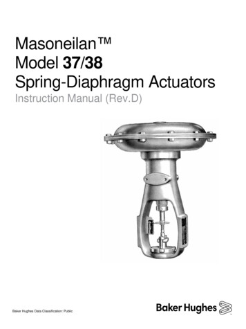
Directional control valves aredevices which influencethe path taken by an air stream. The directional control valve isrepresented by two numbers. The first number represents thenumber of ports, and the secondnumber represents the number ofpositionsDCV Ports and positions
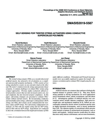
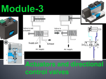
a) 3/2 way DCV-push button- Normally Closed (N/C)(a) pressureport (1) isblockedFunction: The DCV allows the air flow into differentpaths from one or more sources.Way of operation: A 3/2-way valve has 3 ports and 2 switchingpositions.(b) 3/2 way DCV push button (NC)(before actuation) Normally closed means that compressed aircannot flow initially through the valve. When the pushbutton is actuated the valve isopened, thus allowing the air to flow from port (1)to port (2) as shown in Fig. 3.3.Fig. 3.3: 3/2 way DCV pushbutton (N/C) after actuation
Un-actuated In normally closed 3/2 way valve, a spring-loaded disk sealblocks the air flow from the air supply port (1) to the workingport (2). The working port (2) is connectedwith exhaust port (3) as shown in Figon the right.(b) 3/2 way DCV push button(NC) (before actuation
Actuated Allows the flow from port (1) toport (2) and blocking the exhaustport (3) as shown in Fig. (3.3). ISOsymbol of 3/2 way valvenormally closed (N/C) andspring reset. Pictureof the valve.
b) 3/2-DCV - push button- Normally Open (N/O)Way of operation: Normally open means that compressedair flows through the valve as shown in(a) 3/2 way directionalFig. (3.5.a).control valve N/O When the push button is actuated the valve is closed, thusstopping the air to flow from port (1) to port (2).
Un-actuated In the normally open 3/2 way valve,a springloaded disk blocks exhaust port (3).supply port (1) is connected to theworking port (2). The airISO symbol of 3/2 wayDCV push button (NO)Actuated Allows the flow from port (2) to port (3) andblocking the supply air port (1). Fig. (3.5.b) to the left shows the ISO symbol of 3/2 way valveNormally open (N/O) and spring reset, and Fig. 5.5.cshows the picture of the valve.Picture of 3/2 way DCVpush button (N/O).
c) 3/2 Way-DCV- Roller Lever Valve- Normally closed (N/C) One of the most important types of valve actuation. It is generally known as pneumatic limit switch.Symbol and ConstructionISO symbolPicture of the roller levervalveConstruction
Way of operation: This valve is actuated by pressing the roller levere.g. by means of cylinder trip cam. Thevalve is returned to the normal position viareturn spring after releasing the roller lever.
d) 3/2 way, DCV selector valve The way of operation of the selector valve is thesame as the 3/2 DCV push button. The only difference that the selector valve iskeeping the last position active either it isNO or NC. Fig. 3.7 shows the picture and the ISO symbolof the 3/2 way, selector valve.
e) 5/2 way Directional Control Valve This valve contains 5 ports and 2 positions. The 5/2 DCV could be actuated manually or by using pressureactuation (single pilot and double pilot), or by electricalactuation (solenoid).
Before actuation When the 5/2-way valve is not actuated,the flow will be from port (1) to port (2) (a) Initial position (before actuation)while the exhaust will be from port (4)to port (5) as illustrated in Fig. 3.8.aAfter actuation After operating the valve by any method,the valve will be shifted to the other(b) Second position (after actuation)position and in this case, theflow will be from port (1) to port(4) while the exhaust will be fromISO symbol of5/2 way valveport (2) to port (3) as shownin Fig. (3.8.b).
a) 5/2 way selector valve This valve is used for manual operation.You can control the valve by selector switch.It is used in simple applications.Fig. 3.9 above shows the picture and the ISO symbol of the valve. The valve keeps the last position active as the 3/2 way selector.
b) 5/2 way single pilot valve This valve is used for automatic operationYou can control the valve by a pneumatic signal and a springreturn.Fig. 3.10 above shows the picture and the ISO symbol of thevalve.
c) 5/2 way double pilot valve This valve is used for automatic operation You can control the valve by two pneumatic signals The valve keeps the last position after removing the appliedsignal, and it is sometimes called memory valve.Fig.3.11 above shows the picture and the ISO symbol of thevalve.
The pneumatic directional controlvalves can be actuated (operated) inseveral ways such as follows:1. Manual Actuators2. Mechanical Actuators3. Electrical Actuators
A video for you Linear Actuators
1. Manual actuatorsFig. (3.12.a) shows (from left to right)three manual actuation methods: manual,push button and foot pedal.2. Mechanical actuatorsFig. (3.12.b) shows (from left to right) twomechanical actuation methods: roller andidle return roller.3. Electrical actuatorsFig. (3.12.c) shows an example ofelectrical actuation (solenoid valve).See figure on page 8 inmodule 3See figure on page 8 inmodule 3
A video on Pneumatics Actuators in deo 2
Theyare used to produce the required forces in thepneumatic systems. Thepneumatic actuators are divided into:Linear actuators– Single acting cylinder– Double acting cylinderRotary actuators– Air motors
Singleacting cylinder is an output device.Its function:To convert the pressure energy tomechanical energy (linear force in onedirection only).
Thepiston rod of a singleacting cylinder is to advancewhen a push button isoperated. When thepush button isreleased, the piston is toautomatically return to theinitial position. A 3/2-wayvalve controls thesingle-acting cylinder. Thevalve switches from theinitial position into the flowposition, when the push-buttonactuator is pressed.
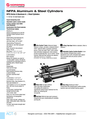
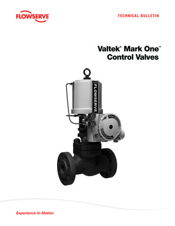
Double acting cylinder is an outputdevice. Its function to convert the pressureenergy to mechanical energy(linear force and motion in twodirections).Note:The force produced by the piston during theadvance stroke is greater than the forceproduced during the return stroke due to the areadifference between the two sides of the piston.
The piston rod of a double-actingcylinder is to advance when a 5/2selector valve is operated and to returnto the initial position when the selectorswitch is back to the normal position. The double-acting cylinder can carryout work in both directions of motion,due to the full air supply pressure beingavailable for extension and retraction.A direct control circuit of a double actingcylinder is shown in Fig. 3.15 to the left.
1. Opening and closing doors,2. Taking items off conveyor belts and putting items onconveyor belts.3. Lifting and moving packages around.4. Presses and punches.
Comparison between single anddouble acting cylinderSERIALSINGLE ACTING CYLINDERDOUBLE ACTING CYLINDER1It has one portIt has 2 ports2It has a spring.It has no spring3It exerts force in onedirection only.It exerts force in 2directions(forward and backward)4It uses compressed air in It uses compressed air inthe forward stroke while both forward andthe return stroke isbackward strokesachieved by the spring.
How to control pneumaticcylinders?There are two ways to controlpneumatic cylinders:1- Direct control2- Indirect control
The simplest level of control for the single or doubleacting cylinder involves direct control signals. The cylinder is actuated directly via a manually ormechanically actuated valve, without any intermediate aswitching of additional directional control valves. If the port sizes and the flow values of the valve are toolarge, the operating forces required may be too great fordirect manual operation.Reference values for limits of direct cylinder control:Cylinder with piston diameter smaller than 40 mmValves with connection sizes smaller than 1/4"
Cylinderswith a large piston diameter have a high airrequirement. A controlelement with high nominal flow rate must beused to actuate these. Ifthe force should prove too high for a manualactuation of the valve, then an indirect actuationshould be constructed, whereby a signal is generatedvia a second smaller valve, which will provide theforce necessary to switch the control element.
The following safety precautions should be strictly followed in thepneumatics lab.1. Wear the safety gear before starting any practical work on the trainer.2. The working pressure shouldn’t exceed 6 bar, that could be achievedby adjusting the pressure regulator in the air service unit to 6 bar.3. Securely plug in pneumatic devices.4. Keep piston rod travel free.5. Check all connections before connecting the compressed air.6. Do not exceed the maximum pressure.7. Do not completely unscrew the regulating screw.8. Tighten each locknut after setting the regulating screw.9. Never tighten the regulating screw with force.10. Never operate roller by hands.11. Connect the compressed air supply only when you complete allconnections.
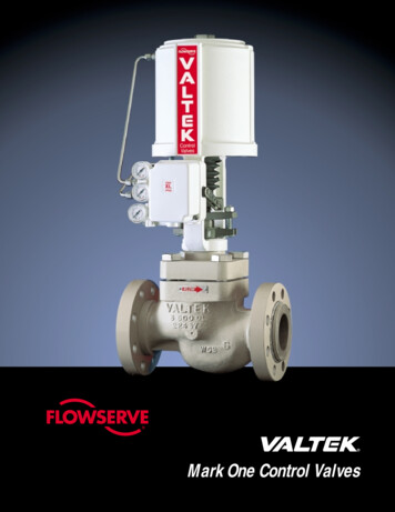
7.1 Learning objectives: Upon the completion of this task, the studentwill be familiar with indirect actuation of adouble acting cylinder by using a double pilotvalve. Using the 3/2 way roller valve for automaticreturn of the cylinder.Fig. 3.16: Positional sketch7.2 Task description:Wooden planks are to be pushed along from a gravity feed magazine to aclamping device as shown in Fig.3.16.By pressing a pushbutton valve one plank is pushed by the slide out of thegravity feed magazine.After the slide has reached the forward end position itreturns to its start position.
7.3 Task requirements:1. Draw pneumatic circuit diagram to control themovement of the slide.2. Simulate the circuit using Fluid SIM software.3. Assemble the circuit practically and check itsoperation.Draw the Pneumatic Circuit in thetable provided in your module
8.1 Learning objectives:Upon the completion of this task, the student will beFig. 3.17: Positional sketch Familiar with indirect actuation of a double actingcylinder by using a double pilot valve. Familiar with using different types of directional control valves.8.2 Task description: Using a diverting device, parts are to be moved from oneconveyor track onto the other in a linear sequence asillustrated in Fig. 3.17. By operating a selector valve the oscillating piston rod of acylinder pushes the turntable via a pawl in stepped sequence. The parts are diverted and transported onwards in theopposite direction. By returning the selector valve back to the normal positionThe drive unit is switched off.
8.3 Task requirements:1. Draw a pneumatic circuit diagram to control theoperation of the piston.2. Simulate the circuit using FluidSIM software.3. Assemble the circuit practically and check itsoperation.Draw the Pneumatic Circuit in thetable provided in your module
9.1 Learning objectives:Upon the completion of this task, the students will be Familiar with indirect actuation of a single acting cylinder. Able to compare between direct and indirect control.9.2 Task description:A single-acting cylinder with a large piston diameter is to clampa workpiece following actuation of a push button. The cylinder isto retract once the push button is released.Positional sketch
9.3 Task requirements:1. Draw a pneumatic circuit diagram to controlthe operation of the piston.2. Simulate the circuit using FluidSIM software.3. Assemble the circuit practically and check itsoperation.Draw the Pneumatic Circuit in thetable provided in your module
10. For further reading, you can use the followinglinks:1- www.Fest-didactic.com2- http://www.eng2all.com/vb/t28932.html3- http://www.logiclab.hu/lesson.php?fe 211. Supplementary recourses1. Pneumatics video from Festo.2. FluidSIM software.12. References1- Festo manuals and workbook TP1012- Festo manuals and textbook TP101
Do the worksheet at theend of module 3 in class
Don’t forget to submithomework 3 next week/classafter the long weekend
If the port sizes and the flow values of the valve are too large, the operating forces required may be too great for direct manual operation. Reference values for limits of direct cylinder control: Cylinder with piston diameter smaller than 40 mm Valves with connection sizes smaller than 1/4" Cylinders with a large piston diameter have a high air requirement. A control element with high .