Transcription
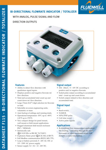
DATASHEET F115 - BI-DIRECTIONAL FLOWRATE INDICATOR / TOTALIZERBI-DIRECTIONAL FLOWRATE INDICATOR / TOTALIZERWITH ANALOG, PULSE SIGNAL AND FLOWDIRECTION OUTPUTSFeaturesSignal output Ability to detect flow direction withquadrature signal inputs. Displays positive and negative flowrate ref.flow direction. Total and accumulated total count up andcount down ref. flow direction. Large 17mm (0.67") digit selection for flowrateor total. Selectable on-screen engineering units;volumetric or mass. Auto backup of settings and running totals. Operational temperature -30 C up to 80 C(-22 F up to 178 F). Very compact design for panel mount,wall mount or field mount applications. Rugged aluminum field mount enclosureIP67 / NEMA4X. Intrinsically safeII 1GD EEx ia IIB/IIC T4 T100 C. Explosion/flame proofII 2G EEx d IIB T5. Full Modbus communication RS232/485/TTL. Loop or battery powered, 8 - 24V AC/DC or115 - 230V AC power supply. Sensor supply 3.2 - 8.2 - 12 - 24V DC. (0)4 - 20mA / 0 - 10V DC according topositive and/or negative flowrate. Scaled pulse output according to accumulatedtotal - count up and count down. Switch output related to flow direction andaccumulated total.Signal inputFlow Reed-switch. NAMUR. NPN/PNP pulse. Coil (sine wave). Active pulse signals.Applications Bi-directional flow measurement applicationslike loading / unloading through the sameflowmeter or where undesired return flowdisturbs a correct totalisation.
General informationSignal inputIntroductionThe F115 will accept most pulse input signals forThe F115 has been developed for applicationsflow or mass flow measurement. To detect thewhere the direction of flow is an issue. Applicationsdirection of flow, it is required to offer two signalscan be found by loading and unloading of ships90 or 240 out of phase. The input signal typeswhere one bi-directional flowmeter is used. Ancan be selected for both inputs in the configurationother application is the correction of back-flow duemenu without having to adjust any sensitiveto shocks in a pipeline caused by piston pumps ormechanical dip-switches or jumpers. Differentvalve behavior. It is required to offer two pulsetypes of sensors are allowed for both inputs.signals from the flowmeter which are 90 or 240 degrees out of phase. A wide selection of optionsCommunicationfurther enhance this models capabilities.All process data and settings can be read andmodified manually or through the ModbusDisplaycommunication link (RS232 / RS485).The display has large 17mm (0.67”) and 8mmFull Modbus functionality remains available for(0.31”) digits which can be set to show flowratethe Intrinsically Safe version (TTL).and totals. On-screen engineering units are easilyconfigured from a comprehensive selection. In caseHazardous areasof a reverse flow, the flowrate will be displayed asFor hazardous area applications, this model hasa negative value. The totalisers will count down.been ATEX certified intrinsically safeII 1 GDEEx ia IIB / IIC T4 T100 C with an allowedConfigurationoperational temperature of -30 C to 70 CAll configuration settings are accessed via a simple(-22 F to 158 F). A flame proof enclosure is alsooperator menu which can be pass-code protected.available with the ratingII 2 G EEx d IIB T5.Each setting is clearly indicated with an alphanumerical description, therefore avoiding confusingEnclosuresabbreviations and baffling codes. Once familiarVarious types of enclosures can be selected, allwith one F-series product, you will be able toATEX approved. As standard the F115 is suppliedprogram all models in the series without a manual.in an ABS panel mount enclosure, which can beAll settings and totals are safely stored in EEPROMconverted to an ABS field mount enclosure.memory in the event of sudden power failure.Most popular is our rugged aluminum fieldmount enclosure with IP67 / NEMA 4X rating.Analog output signalBoth European or U.S. cable gland entry threadsThe positive and / or negative flowrate is re-trans-are available.mitted with the (0)4 - 20mA or 0 - 10V DC outputsignal. The output signal is updated ten times perOverview application F115second. The output value is user defined in relationto the flowrate, e.g. 4mA equals to 0L / Hr andmA20mA equals to or -200L / Hr. The output signalcan be passive, active or isolated where the passiveoutput type will loop power the F115.Pulse outputNegative total outputAnalog outputCommunication linkPulse outputThe scaleable pulse output, reflects the count on theaccumulated display. More over, if the transmittedpulse reflects a count-down situation due toreverse flow, the second output will be switched.The pulse length is user defined from 0.008 second90º or 270ºout of phaseup to 2 seconds. The maximum output frequencyis 64Hz. The output signal can be a passive NPN,active PNP or an isolated electro-mechanical relay.F115
5.1"front-viewrear-view1/2" NPT1/2" NPT1/2" NPT4.41"1.2" 1.2"bottom-view PB: battery poweredInternal long life Lithium battery(terminals GND - 1 - 2 are not available)PX: 8-24V ACAnalog output reading is not available(terminals GND - 1 - 2 are not available) OR: mech. relayPX: 8-24V DCOutput loop powered unit with type AP(terminals GND - 1 - 2 are not available)PM: 115-230V AC-PF: 24V DCPF: 24V AC-IP67 / NEMA 4XTapped holes: U.S. threadPD-XI: 16-30V DCEnclosure HUAluminum field mount enclosureOT: passive trans.bottom-view (1.65")- OR: mech. relay OT: passive trans.(0.2")7I I I I I U AP: no signalUAU: 0-10VIAP: 4-20mAI-AI: 4-20mAI-AF: 4-20mAIAB: 0-20mAI8-- P: active signalP: namurP: PNP P: reed switch / NPN1114-- P: active signalP: namurP: PNP P: reed switch / NPNP: coil1213P: coil910IP67 / NEMA 4XHoles user definedAA: 4-20mAEnclosure HDABS wall mount enclosure6panel cut-out51516IP65 / NEMA 4OA: active 24V DC1718ENCLOSURE HC (STANDARD)ABS PANEL MOUNT ENCLOSUREPD: 8-24V DC4219panel cut-out4rear-view202122(4.528")323IP65 / NEMA 4OA: active 24V DC2425Enclosure HBAluminum panel mount enclosure227AADTR 12VRXDCT: TTL Intrinsically SafeCI: RS485 - 4 wireCH: RS485 - 2 wireRXD28TXDBBTXD29COMMUNICATION(0.71") 18 15 (0.59")(2.28")(1.1")Y308 (0.315")(4.5")28(2.24")11458DTR 12VCB: RS23226bottom-view1side-view30GND(5.1")(1.18") (1.18")PD: 8-24V AC(5.1")FLOWMETER INPUT B115FLOWMETER INPUT Aside-viewANALOG OUTPUT(3.78")5730PULSE OUTPUT R196115PG9NEGATIVETOTAL OUTPUT R2front-view(2.8")5M20POWER SUPPLY13024 nt-view42front-view25 1301122.28"0.315"114(5.1")1.1"(4.5")130PG9 F1152.24"114Z31IP67 / NEMA 4XTapped holes: European thread 4.5"Dimensions enclosuresTerminal connectionsEnclosure HAAluminum field mount enclosure(0.98")(5.1")(0.94")(4.528")
Typical wiring diagram F115-P-(AP)-CH-PB-(OT)BATTERY POWEREDTERMINAL CONNECTORSF100 - seriesTypical wiring diagram F115-P-AP-CH-OTTERMINAL CONNECTORSF100 - seriesOUTPUT LOOP POWEREDModbus communication type CH: RS485 - 2 wire29A28A261413121110Analog output type AP:passive 4 - 20mA (loop powered)89Circuit depends ontype of signal10Flowmeter inputtype: PpulseSignalAnalog output type AP:(not used in this example)e.g. indicatorCommon ground7Common groundSupply *Common ground78Common groundCircuit depends ontype of signal14131211Flowmeter inputtype: PpulseSignalFlowmeter inputtype: PpulseSignalCommon groundSupply *9Circuit depends ontype of signalFlowmeter inputtype: PpulseSignalSupply *8 - 24V DC-Supply *Common groundCircuit depends ontype of signalCommon ground Common ground262729B28Modbus communication type CH: RS485 - 2 wireB6Common ground5Common ground56e.g. counterPulse output type OT:passive transistor(not used in this example)123456Pulse output type OT:passive transistor4Common ground3Common ground34negative total valueSwitch output type OT:passive transistor(not used in this example)Switch output type OT:passive transistorPlease note: AP may be usedin combination with thebattery!AP will power the unit(output loop powered);the battery will be disabledautomatically untill poweris disconnected).*Supply voltage: 1.2 - 3.2V DC to sensor*Supply voltage: 1.2 - 3.2V DC to sensorF115
29RXDA10Flowmeter inputtype: Ppulse26141312Flowmeter inputtype: PpulseSupply *11Circuit depends ontype of signal11Common groundSignalCommon groundSupply *SignalSupply *SignalCommon ground10Flowmeter inputtype: Ppulse1213SignalCircuit depends ontype of signal14Supply *Common groundModbus communication type CI: RS485 - 4 wireFlowmeter inputtype: Ppulse926Common ground9Circuit depends ontype of signalCommon ground115 - 230V AC POWER SUPPLY27TXDBDTR12VCircuit depends ontype of signalY28Modbus communication type CB: RS232Z31TERMINAL CONNECTORSF100 - series3024V AC / DC POWER SUPPLY29TERMINAL CONNECTORSF100 - seriesTypical wiring diagram F115-P-AI-CI-OR-PM28Typical wiring diagram F115-P-AA-CB-OA-PD-87Analog output type AI: 8 - 24V DCpassive isolated 4 - 20mA7 Common groundAnalog output type AA:active 4 - 20mA-e.g. indicator 8e.g. indicator6 Pulse output type OA:active 24V DC signal52233negative total valueF11510*Supply voltage: 1.2 - 3.2 - 8.2 - 12 - 24V DC to sensorL1Power supply type PM:115 - 230V ACNEarth8 - 24V DC-Power supply type PD:8 - 24V AC / DCMain supply 18 - 24V AC0 4Switch output type OA:active 24V DC signalMain supplyCommon groundSwitch output type OR:mechanic relay4negative total valueCommon ground123456e.g. counter5Common ground6e.g. counter123456EarthCommon ground*Supply voltage: 1.2 - 3.2 - 8.2 - 12 - 24V DC to sensor
HAZARDOUS AREATXD29RXD28TERMINAL CONNECTORSF100 - seriesDTR 12VCommon groundSAFE AREAModbus communication type CT: TTLPossible for battery powered applications(not used in this example).Please note: communciation type CTis not allowed in IIC applications.27The F115-XI has been ATEX approved byKEMA for use in intrinsically safe applications.It is approved according toII 1GD EEx iaIIB/IIC T4 T100 C for gas and dustapplications with an operational temperaturerange of -30 C to 70 C (-22 F to 158 F).Besides the two I.S. power supply for thepulse and flow-direction outputs, it isallowed to connect up to four I.S. powersupplies in IIB applications or one in IICapplications. Full functionality of the F115remains available, including 4 - 20mA output,pulse and flow-direction outputs andModbus communication (type CT). Powersupply type PD-XI offers a 8.2V sensorsupply e.g. for one Namur sensor. A flameproof enclosure with ratingII 2G EEx dIIB T5 is available as well. Please contact yoursupplier for further details.Configuration example IIB and IICF115-P-(AP)-(CT)-(OT)-PB-XI - battery powered unit26Hazardous area applications14Supply *Flowmeter inputtype: Ppulse11Supply *SignalFlowmeter inputtype: PpulseAnalog output type AP:passive 4 - 20mA(not used in this example).5Common groundPulse output type OT:passive transistor(not used in this example).4Common ground36Common groundCi is negligiblysmall78Common ground10Circuit depends ontype of signalCommon groundCi is negligiblysmall1213Signal9Circuit depends ontype of signalCertificate of conformity KEMA 03ATEX1074 XPlease note: type AP may be usedin combination with the battery(type PB), but only in IIB applications!AP will power the unit(output loop powered);the battery will be disabledautomatically till poweris disconnected).* Note sensor supply voltage: 1.2V DC for coil sensors or 3.2V DC for other pulse sensors.F115
Configuration example IIB and IIC - F115-P-AP-(CT)-OT-XI - output loop poweredHAZARDOUS AREATERMINAL CONNECTORSF100 - seriesSAFE AREATXD29Modbus communication type CT: TTLPlease note: communciation type CT is not allowed in IIC applications.RXD28Uo 30V 27Po 850mWFor example: MTL50512614Supply *Flowmeter inputtype: PpulseCi is negligiblysmall1213SignalCommon ground11Supply *Flowmeter inputtype: PpulseSignalCommon ground10Circuit depends ontype of signale.g. PCCi is negligiblysmall9Circuit depends ontype of signalCommon ground -DTR 12VIo 250mAISOLATOR:I.S. Certified IsolatorTTL toRS232 / RS422 / TTLe.g. indicatorAnalog output type AP:passive 4 - 20mA (output loop powered)76534For exampleMTL5025 / MTL5011BUo 30VPOWER SUPPLYor SWITCH INTERFACEPo 750mWSwitch output type OT:passive transistor* Note sensor supply voltage: 1.2V DC for coil sensors or 3.2V DC for other pulse sensors.F115Po 750mW-Common groundPOWER SUPPLYor SWITCH INTERFACEUo 30Ve.g. indicator123456Io 100mAnegative total valueCi is negligiblysmallFor exampleMTL5025 / MTL5042 123456Po 750mW-Common groundPulse output type OT:passive transistorPOWER SUPPLYand / or REPEATER e.g. counterCi is negligiblysmallUo 30VIo 100mA-8 Common groundCi 17nFe.g. counterIo 100mAFor exampleMTL5025 / MTL5011Be.g. relay
Configuration example IIB and IIC - F115-P-AF-(CT)-OT-PD-XI - power supply 16 - 30V DCHAZARDOUS AREATERMINAL CONNECTORSF100 - seriesSAFE AREATXD29Modbus communication type CT: TTLPlease note: communciation type CT is not allowed in IIC applications.RXD28Uo 30V 27For example: MTL50512614Supply *Ci is negligiblysmallFlowmeter inputtype: Ppulse1213SignalCommon ground11Supply *SignalCi is negligiblysmallFlowmeter inputtype: PpulseTOTAL Co OF ALL CONNECTEDAPPARATUS MAY NOT EXCEED66nF MINUS 17nF(17nF IS USED BY THE ANALOGOUTPUT SIGNAL TERMINAL 7 8)Analog output type AF:passive floating 4 - 20mACi 17nFe.g. indicator1234565432Po 750mWFor exampleMTL5025 / MTL5011BUo 30VPOWER SUPPLYIo 100mAPower supply type PD: 16 - 30V DC(please note: two power supplies PD and battery supply (type PB) is NOT allowed in IIC applications).e.g. counterIo 100mA10Common groundPOWER SUPPLYor SWITCH INTERFACEUo 30V-Main supplyFor exampleMTL5025 / MTL5011BControl output type OT:passive transistorDue to analog output type AF, the unit has to be powered withwith external power supply type PD.123456Po 750mW Common groundCi is negligiblysmallPOWER SUPPLYor SWITCH INTERFACE-negative total valueUo 30VIo 100mAe.g. counter Pulse output type OT:passive transistor-Common groundCi is negligiblysmall 678Common ground10Circuit depen
wall mount or field mount applications. Rugged aluminum field mount enclosure IP67 / NEMA4X. Intrinsically safe II 1GD EEx ia IIB/IIC T4 T100 C. Explosion/flame proof II 2G EEx d IIB T5. Full Modbus communication RS232/485/TTL. Loop or battery powered, 8 - 24V AC/DC or 115 - 230V AC power supply. Sensor supply 3.2 - 8.2 - 12 - 24V DC. Signal output (0)4 - 20mA / 0 .