Transcription
Valtek MegaStreamValtek MegaStreamControl Valves1
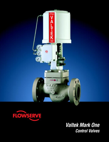
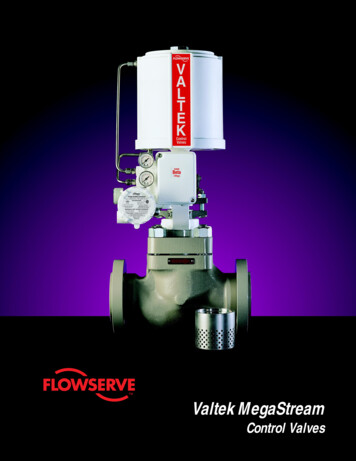
Valtek MegaStreamFigure 1: MegaStream TrimThe Valtek MegaStream valve trim effectively reducesgaseous noise in automatic control valves. MegaStreamtrim is available in two styles: the economical, interchangeable one and the two-stage retainer for noise reduction upto 15 dBA, and the multistage retainer for noise reductionapproaching 30 dBA.The concepts of noise generation have been explored indetail at the Valtek gaseous noise test facility. Withadvanced computer programs, the anticipated noise generated by any control valve can be easily determined.The MegaStream concept and principle, explained indetail on the following pages, are the result of extensiveresearch and engineering study. These principles havebeen incorporated into the trim design, allowingMegaStream to be used in a wide variety of applications:chemical/petroleum plants, refineries, power plants, process industries, nuclear industries, and wherever a highlysuccessful noise reduction valve is required.Some of the built-in design features of MegaStream noisecontrol valves are:1. Staged pressure reduction through a series of carefully designed drilled-hole cylinders called “stages.”2. Velocity control.3. Turbulence control.4. Acoustic impedance.5. Generous plug-to-inner-stage clearance which avoidsgalling and sticking.MegaStream’s design simplicity has reduced the cost ofnoise reduction valves by using many standard parts andby avoiding unnecessary hardening of inner surfaces.2Figure 2: MegaStream Polariscope DisplayA basic principle of MegaStream noise control valves is therestructuring of noise generating turbulence. This principle is clearly illustrated in this polariscope display (Figure2) of MegaStream trim with birefringent fluid. Note theturbulence generated in the fluid as it passes through theseat and how this turbulence decreases as the flowcontinues through each successive stage.
Valtek MegaStreamThe Basic PrinciplesIn conventional single-throttling-point globe controlvalves, a vena contracta (point of greatest flow constriction) occurs immediately downstream of the throttlingpoint. A simplified pressure profile of the fluid as itpasses through the valve shows slight pressure lossesin the inlet and outlet passages, and a substantialreduction of pressure at the vena contracta. Note thatthe overall pressure drop between the inlet and theoutlet does not reveal how far the pressure may havedropped within the valve (Pressure atVena Contracta)Pressure Profile Single SeatVVCThe Problem with GasesThe problem becomes apparent by superimposing avelocity profile on the pressure profile, discussedabove. For single-throttling-point control valves, withthe sharp pressure reduction, the velocity will be greatlyincreased at the vena contracta. While considerablenoise can be generated as velocities in the valveapproach sonic levels, substantial noise can be generated even where inlet and outlet velocities are significantly less than sonic.P1V2P2V1Gaseous NoiseThe SolutionThe solution to the problem is to reduce the pressurefrom inlet to outlet gradually without allowing a sharppressure drop at the vena contracta. Thus, gaseousvelocities are maintained at reasonable valuesthroughout the valve and high noise levels are simplynot generated. Also, by breaking the flow into manysmall flow streams, turbulent energy is reduced anddissipated. In addition, noise generated upstream issubstantially blocked by successive stages.(Velocity atVena Contracta)P1V1PVCV2P2The SolutionFigure 3: Pressure / Velocity Graphs3
Valtek MegaStreamMegaStream – The Effective SolutionValtek MegaStream trim eliminates the problem ofcontrol valve noise by dealing effectively with gaseouspressure reduction, and by controlling turbulence carried into the downstream piping.OPressure ReductionThe pressure drop in MegaStream trim is distributed sothat it occurs not only at the throttling point between theplug and seat, but also at each stage, from the insideof the retainer to the outside. This pressure drop occurslargely as a result of the sudden expansions andcontractions that take place as the flow passes throughthe MegaStream trim. Each stage is designed to takea small pressure drop, avoiding the high velocitiespresent in single-throttling-point trims. This gradualpressure reduction is achieved by designing sufficientstages to keep the velocity low.SFigure 5: Downstream Piping Noise withStandard ValveTurbulence GenerationControl valve noise is largely a result of turbulencegenerated within the valve. This turbulence is carriedinto the downstream piping where the localized pressure changes resulting from the turbulence vibrate therelatively thin pipe wall which radiates noise to thesurroundings. Valtek MegaStream control valves aredesigned to control this turbulence. Each stage is designed with a large number of holes or orifices. Eachsuccessive stage has additional holes or orifices, permitting increased flow area to handle the increased gasvolume resulting from the pressure drop.Figure 4: MegaStream StagesEach retainer stage of MegaStream trim handles aportion of the pressure drop, significantly reducing thehigh velocity and the turbulence generated by thesingle throttling point.4The turbulence present in the fluid as it leaves the finalstage of the MegaStream trim is limited by controllingthe physical size of the individual fluid streams. Thesmaller fluid stream size exiting the final stage of theMegaStream trim limits the amount of turbulence energy present. Further, the smaller turbulent eddies aremore easily dissipated. The result is a fluid stream leavingthe valve that contains no large-scale turbulent eddiessufficient to cause substantial noise generation in thedownstream piping. The stages also effectively limitmuch of the sound vibration generated at the throttlingarea. This attenuating effect is made possible by theacoustic impedance characteristics of the material anddesign, which provide resistance to further transmission of incident sound energy. The acoustic impedancedescribed is a principal factor permitting the control ofnoise when the valve plug is throttled close to the seat.
Valtek MegaStreamVelocitiesOne of the fundamental design considerations withMegaStream control valves is maintaining reasonableand acceptable velocities at every point as the flowpasses through the valve. This requires careful attention to flow areas and area ratios at the various stagesin the retainer, as well as elsewhere in the valve.With gases, it is commonly understood that as thevelocity approaches the speed of sound the valve willbe noisy. Control valve noise often becomes excessivefor velocities much less than sonic. Valtek MegaStreamvalves are designed for an optimal maximum gasvelocity of mach 0.33 at the valve outlet. The MegaStream design engineer carefully assesses velocities forthe most critical flowing conditions at the followingpoints (refer to Figure 6):1. The inlet passageway to the valve.2. The internal flow area of the MegaStream retainer atvarious plug positions.3. The gallery flow area formed between the outsidediameter of the retainer and the inside diameter ofthe valve body.342FLOW4. The valve outlet passage flow area. For proper noisecontrol, the downstream piping must be equal to orlarger than the valve outlet size.Heavy-duty Top-stem GuidingMegaStream valves utilize heavy-duty, top-stem guiding for several reasons:1. Since the flow characteristics of the MegaStreamvalve are determined by the shape of the plug, it isa relatively simple matter of changing the plug toprovide equal percentage, linear or quick-open trim.Changing the characteristic of a cage-guided valverequires replacement of the cage, which is veryexpensive.2. Double, top-stem guiding eliminates the cost ofhardened materials associated with cage-guiding.Even when the proper materials are used, cageguided valves will often gall or bind.3. Double, top-stem guiding eliminates tight clearances in the flow stream. Wider clearances allowsmall particles to pass through the valve withoutcausing sticking or galling.1Figure 6: Velocity CheckpointsWARNING: High acoustic noise levels are accompanied by high mechanical vibration levels. Thesevibration levels can cause failure of the valve,piping or associated equipment resulting in property damage and/or personal injury. Acoustic noiseand mechanical vibration levels are greatly compounded (up to 50 times) when the frequency of theexcitation matches acoustic and/or mechanicalnatural frequencies of the system. Noise controltrim (source treatment) should always be considered in any high energy (high pressure and highflow) and/or resonant noise/vibration applications.5
Valtek MegaStreamFlow CharacteristicsValve Size EstimationThree flow characteristics are available in MegaStreamcontrol valves.To estimate the required MegaStream valve size, usethe following procedure:“Equal percentage” is the most common characteristicin process control. Here, the change in flow per unit ofvalve stroke is directly proportional to the flow occurringbefore the change is made.1. Estimate required flow capacity. For one and twostage retainer designs, use the sizing equations forconventional globe valves (see the Valtek Sizing &Selection Manual, Section 3). Since three throughseven-stage retainers are designed not to choke,the sizing equations must be adjusted by settingXT 1.“Linear” characteristic produces an equal change offlow per unit of valve stroke. This characteristic isgenerally used on those systems where pressure dropis relatively constant or the valve pressure drop is amajor portion of the total system drop.“Quick-open” characteristic is used for on-off service.This characteristic is designed to provide maximumflow quickly and, when used with the MegaStreamretainer, effectively reduces noise.Gaseous Noise TestingTests are continually underway at the Valtek gaseousnoise test facility. The facility was developed jointly byValtek engineers and Brigham Young University. Thisfacility has up to 5000 psi blow down capability anddirect computer data acquisition.2. Calculate the pressure drop ratio, P1/ P2 , for themaximum CV condition.3. Using the standard MegaStream data in Table I,locate the valve size that accommodates both therequired CV and the pressure ratio calculated in step2. The pressure ratio must not exceed the maximumP1/P2 limit indicated for the size and CV selected.4. The discharge mach number should be 0.33 or less,except for valves venting to atmosphere whichrequire a mach number of 0.1 or less.NOTE: These calculations indicate an estimated valvesize and CV which must be confirmed by Valtek designengineers. (Other design considerations may also influence the final size selection).Ordering InformationThe following information must be provided whenordering a MegaStream valve:1. Size and type: globe or angle2. Start-up and operating conditions: inlet and outletpressures, temperature, flow rate, fluid's specificgravity or molecular weight, vapor pressure or gascompressibility3. Maximum operating temperatures and pressures4. Maximum allowable sound pressure levels5. Body pressure rating and end connections6. Materials required: trim, body and packing7. Actuator requirements: type (pneumatic ormanual), failure position, size and minimumair supply8. Positioner signal requirements9. Accessories required6
Valtek MegaStreamOne and Two-stage RetainersMegaStream valves equipped with one or two-stageretainers represent an economical and innovativeapproach to low noise applications by permitting upto 15 dBA noise reduction. A standard retainer isconstructed from heavy-duty, 316 stainless steel,drilled-hole cylinders.Since one standard design exists for each valve size,special engineering is not required. This results in lowerprices and quicker deliveries. Because of parts interchangeability with standard seat retainers, one andtwo-stage retainers can be fitted into conventionalMark One valves without special or additional parts.The simplicity of design also permits easy removal andcleaning.Multistage retainer.Multistage RetainersTwo-stage, drilled hole retainer.For larger noise reduction levels (up to 30 dBA), multistage retainers incorporate from three to seven stages.Each stage is welded in place. The outer stage allowsproper gasket compression to be applied to the bonnetand seat gasket.Refer to Figure 7 for standard attenuation data.MegaStream Noise Reduction PossibilitiesFlowserve has developed and made available the Performance! software program for use on IBM and compatible personal computers running Windows 95 orNT. This program can determine within minutes anticipated noise generation levels for conventional valvesand, at the same time, verify the noise reduction capabilities of a MegaStream valve for the same application.Section 13 in the Valtek Sizing & Selection manual alsocontains information dealing with gaseous noise.MegaStream quotations often include guaranteedmaximum noise levels ( 5 dBA) as required to meetyour specifications and OSHA standards.7
Valtek MegaStreamTrim DataTable I: MegaStream Class 150-600 Standard Trim DataValveSize * See page 9 for attenuation vs. P1/P2
Valtek MegaStream One and Two-stage Retainers MegaStream valves equipped with one or two-stage retainers represent an economical and innovative approach to low noise applications by permitting up to 15 dBA noise reduction. A standard retainer is constructed from heavy-duty, 316 stainless steel, drilled-hole cylinders. Since one standard design exists for each valve size, special engineering is .
