Transcription
CARBON P O LY C H A I N G T Belt Drive Systems#175955/12DRIVE DESIGN MANUALDesign your drives online at www.gates.com/drivedesign
Table of ContentsDESCRIPTIONPAGESafety Policy . . . . . . . . . . . . . . . . . . . . . . . . . . . . . . . . . . . . . . . . . . . 1Drive Survey SheetsLow-Speed Drive Design Load Calculationsand Information Sheet . . . . . . . . . . . . . . . . . . . . . . . . . . . . . . 4-7High-Speed Drive Survey and Energy Savings Worksheet . . . . . 8Gates Design IQ Data Worksheet . . . . . . . . . . . . . . . . . . . . . . . . 9Poly Chain GT Carbon Belt DrivesBelt System Specifications. . . . . . . . . . . . . . . . . . . . . . . . . . . . . . . . . 2Gates Poly Chain GT Carbon Belt Standard Line . . . . . . . . . . . . . 3Standard Belt Drive Selection Procedure . . . . . . . . . . . . . . . . 10-13NEMA Minimum Sprocket Diameters . . . . . . . . . . . . . . . . . . . . . 14Poly Chain GT Carbon Belt Service Factors . . . . . . . . . . . . . . . . . 15Poly Chain GT Carbon Belt Drive Selection Tables8mm Pitch Belts. . . . . . . . . . . . . . . . . . . . . . . . . . . . . . . . . . . . . . 16-3114mm Pitch Belts . . . . . . . . . . . . . . . . . . . . . . . . . . . . . . . . . . . . . 32-45Poly Chain GT Carbon Belt Power Rating Tables8mm Pitch Belts . . . . . . . . . . . . . . . . . . . . . . . . . . . . . . . . . . . . . 46-5314mm Pitch Belts . . . . . . . . . . . . . . . . . . . . . . . . . . . . . . . . . . . . . 54-63Poly Chain GT 2 Sprocket SpecificationsSprocket Reference Drawings. . . . . . . . . . . . . . . . . . . . . . . . . . . . . 648mm Pitch Sprocket Dimension Tables. . . . . . . . . . . . . . . . . . 65-6814mm Pitch Sprocket Dimension Tables . . . . . . . . . . . . . . . . . .69-73Sprocket Specifications . . . . . . . . . . . . . . . . . . . . . . . . . . . . . . . . . . 74Bored-To-Size Sprocket Bore Range Listing. . . . . . . . . . . . . . . . . 75Bored-To-Size Sprocket Re-bore Specificationsand Instructions . . . . . . . . . . . . . . . . . . . . . . . . . . . . . . . . . . . . . . 76Taper-Lock BushingsDrawings and Dimension Tables . . . . . . . . . . . . . . . . . . . . . . . . . . 77Stock Bore and Keyseat Information . . . . . . . . . . . . . . . . . . . . 78-79Taper-Lock Type Sprocket Installation and Removal . . . . . . . . . 80Belt Drive Tensioners . . . . . . . . . . . . . . . . . . . . . . . . . . . . . . . . . 81-82Poly Chain GT2 Sprocket Diameter Tables8mm Pitch Table . . . . . . . . . . . . . . . . . . . . . . . . . . . . . . . . . . . . . 83-8414mm Pitch Table . . . . . . . . . . . . . . . . . . . . . . . . . . . . . . . . . . . . 84-85Long-Length BeltingIntroduction . . . . . . . . . . . . . . . . . . . . . . . . . . . . . . . . . . . . . . . . . . . . 86Drive Selection . . . . . . . . . . . . . . . . . . . . . . . . . . . . . . . . . . . . . . . . . 87Clamping Fixtures . . . . . . . . . . . . . . . . . . . . . . . . . . . . . . . . . . . . . . . 87DESCRIPTIONWorld HeadquartersPAGEEngineering DataSection I — Application Design Considerations1. Gear Motors/Speed Reducer Drives . . . . . . . . . . . . . . . . . 94-952. Electric Motor Frame Dimensions . . . . . . . . . . . . . . . . . . . . . . 953. Minimum Recommended SprocketDiameters for General Purpose Electric Motors . . . . . . . . . . 964. High Driven Inertia Drives . . . . . . . . . . . . . . . . . . . . . . . . . . . . . 965. Air Moving Drives . . . . . . . . . . . . . . . . . . . . . . . . . . . . . . . . 96-976. Linear Motion Drives . . . . . . . . . . . . . . . . . . . . . . . . . . . . . . . . . 977. High Performance Vehicle Applications . . . . . . . . . . . . . . . . 978. Belt Drive Registration . . . . . . . . . . . . . . . . . . . . . . . . . . . . . . . . 979. Belt Drive Noise . . . . . . . . . . . . . . . . . . . . . . . . . . . . . . . . . . . . . 9810. Use of Flanged Sprockets . . . . . . . . . . . . . . . . . . . . . . . . . . . . 9811. Fixed (non-adjustable) Center Distance . . . . . . . . . . . . . 98-9912. Use of Idlers . . . . . . . . . . . . . . . . . . . . . . . . . . . . . . . . . . . . . . . . 9913. Specifying Shaft Locations in MultipointDrive Layouts . . . . . . . . . . . . . . . . . . . . . . . . . . . . . . . . . . . 99-10014. Minimum Belt Wrap and Tooth Engagement . . . . . . . . . . 10015. Adverse Operating Environments . . . . . . . . . . . . . . . . . . . . . 100Section II — Engineering Design Considerations1.2.3.4.5.6.7.8.9.Belt Storage and Handling. . . . . . . . . . . . . . . . . . . . . . . . . . . . 101Center Distance and Belt Length . . . . . . . . . . . . . . . . . . . . . . 101Belt Tooth Profiles . . . . . . . . . . . . . . . . . . . . . . . . . . . . . . . . . . . 101Static Conductivity . . . . . . . . . . . . . . . . . . . . . . . . . . . . . . . . . . 102Sprocket Diameter and Speed . . . . . . . . . . . . . . . . . . . . . . . . 102Efficiency . . . . . . . . . . . . . . . . . . . . . . . . . . . . . . . . . . . . . . . . . . . 102Belt Tolerances . . . . . . . . . . . . . . . . . . . . . . . . . . . . . . . . . . . . . 103Belt Installation Tension . . . . . . . . . . . . . . . . . . . . . . . . . . 103-104Center Distance Allowances for Installationand Tensioning . . . . . . . . . . . . . . . . . . . . . . . . . . . . . . . . . . . . . 10510. Drive Alignment . . . . . . . . . . . . . . . . . . . . . . . . . . . . . . . . . 105-10611. Belt Installation. . . . . . . . . . . . . . . . . . . . . . . . . . . . . . . . . . . . . . 10612. Belt Pull Calculations. . . . . . . . . . . . . . . . . . . . . . . . . . . . . . . . . 10613. Bearing/Shaft Load Calculations. . . . . . . . . . . . . . . . . . . . 106-10714. Self-Generated Tension . . . . . . . . . . . . . . . . . . . . . . . . . . . . . . 107Technical DataTroubleshooting . . . . . . . . . . . . . . . . . . . . . . . . . . . . . . . . . . . . 108-109Standard Calculations . . . . . . . . . . . . . . . . . . . . . . . . . . . . . . . . . . 110Useful Formulas and Calculations . . . . . . . . . . . . . . . . . . . . . 111-112Synchronous Belt Product Design Catalogs . . . . . . . . . . . . . . . 113Short-Length 8mm Pitch Poly Chain GT Belt DrivesIntroduction . . . . . . . . . . . . . . . . . . . . . . . . . . . . . . . . . . . . . . . . . . . . 88Belt System Specifications. . . . . . . . . . . . . . . . . . . . . . . . . . . . . . . . 89Stock Belt Lengths and Widths. . . . . . . . . . . . . . . . . . . . . . . . . . 908mm Pitch Belt Drive Selection Tables . . . . . . . . . . . . . . . . . . 90-93ForewordSynchronous belts are being used more extensively than ever before in the industry where synchronization of one shaft speed to another isof primary importance. Gates Corporation has prepared this complete Poly Chain GT Carbon Belt Drive Design Manual to handle these exacting applications. Poly Chain drives also eliminate maintenance and noise problems associated with chain drives and reduce maintenancerequired on other problem power transmission drives.Stock Belt Drives are presented in this manual for your convenience. If your drive requirements (Speed, Ratio, Center Distance, Space,Horsepower) are not met, contact your local Gates representative.Copyright 2009Gates CorporationDenver, Colorado 80202Printed in U.S.A.Gates Corporation1551 Wewatta StreetDenver, Colorado 80202Tel: 303-744-1911www.gates.comFor ExportsGates InterAmericaTel: 954-926-4568Fax: 954-926-8024giamail@gates.comProduct ApplicationEngineersTel: 303-744-5800ptpasupport@gates.com
SAFETY POLICYWARNING! Be Safe! Gates belt drive systems are very reliable when usedsafely and within Gates application recommendations. However, there arespecific USES THAT MUST BE AVOIDED due to the risk of seriousinjury or death. These prohibited misuses include:Primary In-Flight Aircraft SystemsDo not use Gates belts, pulleys or sprockets on aircraft, propeller or rotordrive systems or in-flight accessory drives. Gates belt drive systems arenot intended for aircraft use.Braking SystemsDo not use Gates belts, pulleys or sprockets in applications that dependsolely upon the belt to slow or stop a mass, or to act as a brake withoutan independent safety backup system. Gates belt drive systems are notintended to function as a braking device in “emergency stop” systems.DRIVE DESIGN SOFTWAREDrive design software can be found atwww.gates.com/drivedesign.This software assists designers in quicklyselecting optimum drive solutions.www.gates.com/pt The Driving Force in Power Transmission.1
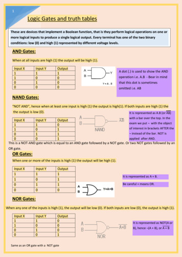
Gates Poly Chain GT Carbon Belt System SpecificationsTo satisfy a wide range of loads, speeds and applications, Poly Chain GTCarbon belts and sprockets are made in a selection of sizes, capacitiesand dimensions.The three principal dimensions of a belt are:pitchpitch lengthwidthBelt pitch is the distance in millimeters between two adjacent tooth centersas measured on the pitch line of the belt. Belt pitch length is the total length(circumference) in millimeters as measured along the pitch line. The theoretical pitch line of a Poly Chain GT Carbon belt lies within the tensile member.The three principal dimensions of a sprocket are:pitchnumber of spr ocket gr ooveswidthOn the sprocket, pitch is the distance between groove centers and is measured on the sprocket’s pitch circle. See illustration at right. The pitch circleof the sprocket coincides with the pitch line of the belt mating with it. Thesprocket’s pitch diameter is always greater than its outside diameter.Any Poly Chain GT Carbon belt must be run with Poly Chain GT2 sprockets of the same pitch.Gates Poly Chain GT Carbon belts are made in 8mm and 14mm pitches.Standard belt sizes are listed in the stock Poly Chain GT Carbon BeltTables on page 3. Specifications for the 8mm and 14mm pitch belts list thebelt pitch lengths, number of teeth, stock widths and appropriate weights.Using the information from these tables, a code for ordering a specific beltcan be determined as shown in the following examples:BeltPitch(mm)8MGT14MGTBeltPitch Length(mm)6401190BeltWidth(mm)1237Sprockets for Poly Chain GT Carbon belts are also made in 8mm and14mm pitches. Standard sprocket sizes are listed in the SprocketSpecification Tables on Pages 64 through 74. For each Poly Chain GTCarbon belt width, there is a table listing the sprocket code symbol, theapplicable bushing style and pertinent dimensional information. Thesprocket code symbol components are determined by using the followingexamples:Pitch(mm)8MX14MXSprocket Designation& No. of Groo ves48S*36S*Width(mm)1237*The “S” is used after the number of grooves to help identify it is a sprocket and avoid any confusion with the belt code.The bushing style to be used with a specific sprocket is listed in theSprocket Specifications Tables. Reference to the Stock Bushings for PolyChain GT2 plus Bore and Keyseat information will give you the data needed to order the proper bushing. For example,Style 2517 Bushing with a 2-inch bore2 Gates Corporationwww.gates.com/pt
Gates Poly Chain GT Carbon Belt Standard LineStock Sizes14mm Pitch Lengths8mm Pitch LengthsDescriptionNo. of 6.38No. of 58mm Widths12mm(.47 in.)21mm(.83 54.33170.32173.6214mm Widths36mm(1.42 in.)62mm(2.44 in.)20mm(.79 in.)37mm(1.46 in.)68mm(2.68 in.)90mm(3.54 in.)125mm(4.92 in.)Long Length Poly Chain GT2 Belting Stock Widths8mm Pitch Widths14mm Pitch Widths12mm21mm36mm20mm37mmSpecial widths available upon request.Dimensions are given in inches and millimeters. Inches are shown in black type. Millimeters are shown in blue type.www.gates.com/pt The Driving Force in Power Transmission.3
Poly Chain GT Carbon Low-Speed Design Load CalculationsFor use when designing Poly Chain GT Carbon belt drives for gearreducer output shafts and general r oller chain conversions.When designing Poly Chain GT Carbon belt drives to be used in low-speedapplications (generally 500 rpm and less), traditional drive design proceduresmay yield drives with greater-than-needed capacity. These design load calculations are intended primarily for applications on the output side of gearreducers, and will yield Poly Chain GT Carbon belt drives competitive in bothcost and performance with roller chain and superior to other belt drives.A recent power transmission industry publication estimated that half of allU.S. motors operate at less than 60 percent of their rated load and one thirdoperate at below 50 percent of their rated load. Significant power losses canalso occur in speed reducers, further reducing the actual torque loads carried by belt drives.In order to prevent over sizing belt drives for these low speed applications,the design should be based upon the actual system running load. Becausethe actual running load may or may not be known, the following threeapproaches are recommended to assist the designer in determining theappropriate design load:I. Actual Operating Loads KnownIn those cases where the actual operating load is known, design the beltdrive for the actual operating load rather than for a load based upon themotor name plate. Use Formula 1 to calculate the proper drive design loadbased upon motor load (name plate or measured) when the belt drive willbe installed on the reducer output shaft.Design LoadFormula 1DesignLoad (MotorLoad) x ServiceFactor x (% Reducer Efficiency/100)Motor Load: From user/OEMService Factor: From Service Factor table% Efficiency: From Speed Reducer Catalog (also refer tothe Reference Data Section)II. Actual Operating Loads Unknown — With MeasurementsWhen the actual system running load is unknown, it must be estimated.This can be done with reasonable accuracy by measuring the averageelectrical amperage draw from the motor while under load, and calculatinga motor horsepower output. Speed reducer efficiency can also be calculated and applied as well.Use Formulas 2-4 for the most accurate results if all of the needed formula values are available.Because values for motor efficiency and power factor may not be readilyavailable, a common industry accepted practice is to proportion the motorname plate horsepower rating with the motor name plate amperage ratingand actual measured amperage value. Use Formula 5 for a reasonableestimate of actual motor horsepower load.Thr ee Phase A.C. MotorsFormula 4Horsepower* 1.73 x (Amps) x (Volts) x (Eff) x (PF)746Amps: as measured (average of 3 phases)Volts: as measuredEff: % Eff/100 (from Motor Catalog or Motor Nameplate)Power Factor: as measured or from Motor Catalog(Note: Refer to Power Factor on page 5 for generalpower factor and efficiency values.)Alternative Appr oachD.C. MotorsFormula 5Horsepower (Nameplate hp)(Measured Amps)(Nameplate Amps)Formula 2Horsepower* (Amps) x (Volts) x (Eff)746Nameplate hp: maximum rated motor horsepower(Motor Nameplate or Motor Catalog)Measured Amps: as measured(if 3 phase; average of 3 phases)Nameplate Amps: maximum rated motor amps(Motor Nameplate or Motor Catalog)Amps: as measuredVolts: as measuredEff: % Eff/100 (from Motor Catalog or Motor Nameplate)Single Phase A.C. MotorFormula 3Horsepower* (Amps) x (Volts) x (Eff) x (PF)746Now with a good estimate of the actual motor horsepower load, useFormula 6 to calculate the proper drive design load (when the belt drive willbe installed on the reducer output shaft).Amps: as measuredVolts: as measuredEff: % Eff/100 (from Motor Catalog or Motor Nameplate)Power Factor: as measured or from Motor CatalogFormula 6Design Load (Estimated Motor Load) x (Service Factor)x % Reducer Efficiency100Estimated Motor Load: From Formulas 2-5Service Factor: From Table 5% Efficiency: from Speed Reducer Catalog(also refer to Speed Reducer Efficiency on page 6.*With an estimate of actual motor load, and the belt drive connected directly to a speed reducer output shaft, use Formula 1 to calculate the drive design load.4 Gates Corporationwww.gates.com/pt
Poly Chain GT Carbon Low-Speed Design Load Calculations – continuedIII. Actual Operating Loads Unknown — Without Measur ementsIt is not always possible to determine actual motor operating loads, as it maynot be possible to take amperage draw measurements from the motor. Inthose cases, the following guidelines should be used with caution, as they maynot yield successful results in every case. They should, however, yield at leastcomparable, if not improved, service compared to the old roller chain drive.The procedures which follow in Table 2 should yield at least comparable, ifnot improved, service compared to the old roller chain drive.Table 1SituationProperly lubricated. Provides more than four monthsof continuous serviceConclusionSystem is either properly designed or lightly loaded.Properly lubricated. Provides less than four monthsof continuous service.System may have less than adequate load capacity.Unlubricated. Provides more than four monthscontinuous service.System is lightly loaded.**Unlubricated. Provides less than four monthscontinuous service.It is difficult to conclude whether the system has beendesigned with adequate load capacity.**RecommendationBase belt drive design load on the roller chain drive horsepower rating.Belt drive design load based on roller chain drive horsepowerrating may result in a poorly performing system. Exercisegood engineering judgment.Base belt drive design load on roller chain drive horsepowerrating.Base belt drive design load on roller chain power rating butexercise good engineering judgment.**Unlubricated roller chain drives do not typically provide more than three to four months of service regardless of design capacity.In those cases where the belt drive design load is based upon the powerrating of the existing roller chain drive, use Formula 7 along with good engineering judgment to calculate the proper drive design load.Formula 7Design Load (Roller Chain Power Rating) x Service FactorRoller Chain Power Rating: from Roller Chain Manufacturer’sCatalogService Factor: from Table 1Drive Selection Pr ocedur eQ hp x 63025rpmQ torque (lb-in)hp horsepowerrpm shaft revolutions/min.Reducer efficiency is then calculated as follows:Reducer Efficiency Output hp or QInput hp or QA general comparison of speed reducer efficiency is included in Table 3.Having used one of the previous three approaches to determine a beltdrive design horsepower load, proceed to step 2 of the Belt Drive SelectionProcedure on page 10.Reference Infor mationMotor DataMotor efficiency and power factor data may not be readily available, Actualvalues vary and are motor dependent. If catalog data are not available, typical values are as follows:Speed Reducer Ef ficiencyPower FactorIf the efficiency of a speed reducer is not published, it can be calculatedindirectly from the catalog data. Speed reducer manufacturers generallypublish rated input horsepower and rated output torque for each speedreducer unit in their product line. In order to calculate speed reducer efficiency, either the rated output torque must be converted to output horsepower or the rated input horsepower must be converted to input torque.The torque/horsepower conversion formulas are as follows:Standard Motor: 0.80 typical (range from 0.55 to 0.90)High Efficiency Motor: 0.85 typical (range from 0.73 to 0.88)Ef ficiencyBelt Tensioning(hp) Q x (rpm)63025Adequate belt installation tension is critical in preventing belt ratchetingunder peak motor starting loads. To calculate proper belt installation tension values for Poly Chain GT Carbon belts, follow the procedures startingon page 103.hp horsepowerQ torque (lb-in)rpm shaft revolutions/minwww.gates.com/ptStandard Motor: 80% typical (range from 70% to 87%)High Efficiency Motor: 88% typical (range from 84% to 93%) The Driving Force in Power Transmission.5
Poly Chain GT Carbon Low-Speed Design Load Calculations – continuedTable 2Reducer TypeStraight Bevel ReducerRatio Range1:1 - 4:1ReductionSingleApprox. Efficiency, (%)97.0%Spiral Bevel Reducer1:1 - 5:1Single97.0%Helical Reducer1.2:1 - 6:1to 30:1to 200:1SingleDoubleTriple97.0%94.1%91.3%Planetary Reducer3.5:1 - 6:1to 30:1to 200:1to .4%Cycloidal Reducer6:1 - 119:1to 7,500:1to 658,000:1SingleDoubleTriple92.5%85.6%79.1%Worm Gear Reducer5:1 - 75:1to 6,000:1SingleDouble45%-94%28%-65%Note: Speed ratio ranges and efficiency values are approximate and vary with each manufacturer.Copy and use this worksheet to estimate actual belt drive operating loadsbased upon the Low-Speed Drive Design Pr ocedureDrive Design Load Worksheet for Low-Speed Poly Chain GT Carbon DrivesTable 3Alternating CurrentKnown ValuesToFind Direct CurrentAmpsVoltsMotor Powerhp Load%Eff/100 FactorMotorrpmReducer ReducerRatio %Eff/100MotorTorqueSingle PhaseThree PhaseMotorAmps(hp) (746)(V) (Eff)(hp) (746)(V) (Eff) (PF)(hp) (746)(173) (V) (Eff) (PF)Motor hp(Amp) (V) (Eff)746(Amp) (V) (Eff) (PF)746(173) (Amp) (V) (Eff) (PF)746MotorTorque(lb-in)(hpLoad) (63025)(Motor rpm)ReducerOutputTorque(Motor Torque) (Reducer Speed Ratio) (Reducer Efficiency)ReducerOutputTorque(hp Load) (Reducer Speed Ratio) (Reducer Efficiency) (63025)(Motor rpm)Notes:1. Amperage measurements should be made under normal operating conditions, or recorded continuously as a function of time.2. In three phase systems, the formula amperage value is determined by averaging the three individual phase measurements together.See Low-Speed Drive Design Information Sheet on page 7for assistance in collecting drive design information.6 Gates Corporationwww.gates.com/pt
Low-Speed Drive Design infor mation SheetFor Drive Selections with Shaft Speeds Less Than 500 rpmDistributorDrive LayoutCustomer:(check one) Drive Identification (location, number, etc.)Motor Reducer BeltDrive DrivenDriveR Infor mation:Motor Nameplate DataRated Horsepower Rated Voltage Rated RPM Efficiency Rated Amps Rated Torque Actual Motor Load Motor Type:AC DCOutput Speed:Constant Gear Motor Variable Reducer Infor mation:Reducer Type (wor m, right angle helical, cycloidal, etc):Reducer Efficiency Output RPM Reducer Ratio Rated Input HP/Torque Rated Output HP/Torque Existing Drive Infor mation:Drive Type:Chain V-BeltIf chain, type; 2/#60. #80, etc.Lubed Synchronous BeltUnlubedBelt Drive on ReducerOutput Shaft Current Drive Service Life DriveR Sprocket/Sheave (teeth/OD) DriveR Shaft Diameter DriveN Sprocket/Sheave (teeth/OD) DriveN Shaft Diameter Center Distance - Motor Belt DriveReducer DrivenType of Center Distance Adjustment:Idler used:Yes No Inside Backside DriveN Information:Type of Equipment: Actual Horsepower Required DriveN RPM Hours/Day Days/Week Weeks/Year Special Requir ements:Space Limitations:Maximum DriveR Dia. Maximim DriveN Dia Maximum DriveR Width Maximum DriveN Width Belt Drive on ReducerInput ShaftEnvironmental Conditions:Temperature Range Belt Conductivity RequiredOil Mistwww.gates.com/pt Oil Splash Moisture Abrasives The Driving Force in Power Transmission.7
High-Speed Drive Sur vey and Ener gy Savings WorksheetCustomer Infor mationCompany: Distributor:Address: Phone: Fax:E-mail:Drive Infor mationI.D. of Drive (location, number, etc.)Description of DriveN EquipmentManufactur er of DriveN EquipmentHorsepower rating of Motor DriveN HP Load (Peak)(Normal)Motor Frame Size Motor Shaft Dia. DriveN Shaft DiaSpeed:DriveR RPM RPM Measured with Contact or Strobe Tachometer Yes NoDriveN RPM Yes NoRPM Measured with Contact or Strobe TachometerSpeed Ratio Speed Up or Speed DownCenter Distance: Minimum Normal MaximumExisting Drive Components: DriveR DriveNBelts Belt ManufacturerAmbient Conditions:Temperature Moisture Oil, etc.Abrasives Shock LoadStatic Conductivity Required? YesNoMaximum Sprocket Diameter (OD) and Width Limitations (for guar d clearance):DriveR: Max. OD Max. Width DriveN: Max. OD Max WidthGuard DescriptionMotor Mount:Double Screw Base? Yes NoMotor Mounted on Sheet Metal? Yes NoAdequate Structure? Yes NoFloating/Pivot Motor Base? Yes NoStar t Up Load:% Motor Rating at Start Up AC Inverter Yes NoSoft Start? Yes NoDuty Cycle:Number of Starts/Stops times per (hour, day, week, etc.)Energy Savings Infor mationEner gy Cost per KW-HourHours of Operation Hours per Day Days per Week Weeks per Year8 Gates Corporationwww.gates.com/pt
Gates Design IQ Data WorksheetCustomer Infor mationCompany: Distributor:Address: Phone: Fax:E-mail:Application Summar yGeneral Description:Pr oduct Type: Pr oduction Volume:Design ParametersDriveR:Motor Type & Description: (Servo, Stepper, DC, AC, etc.)Reversing: (Y/N)Nominal Motor Tor que/Power Output:RPM:Max/Peak Motor Torque/Power Output:RPM:Motor Stall Tor que (If applicable): Driver Rotation: (CW / CCW / Rev)DriveN's/Idlers:DescriptionDriveR(Specify appropriate units for each field; in, mm / hp, kw / lb-ft, lb-in, N-m, etc.)XYPulleyDiameterPitchSprocketGroo vesInside/OutsiderpmLoad(driveN)Conditions#% TimeUnitsShaftDiameterNote: For complex drive layouts use additional pages as neededDrive SketchSlot Movement:Idler DetailsMin PositionXYMax PositionXYSpring:Pivoting Movement:Pivot PointXYSpring:Pivot Arm Radius:Mo vement AngleMin DegMax Deg(in/mm):Special Requir ementsProduct Design Life: Belt Life: Hours/Day: Hours/Year:Pulley Materials:Prototype ProductionAmbient Conditions:Temperature: Moisture: Oil: Static Dissipation: Abrasives:Special Requirements:Note: This worksheet may be used to survey multipoint drives. For more information on specifying shaft locations in multipointdrive layouts, see Engineering Section I-13 on page 99Pagewww.gates.com/pt The Driving Force in Power Transmission.Of9
Poly Chain GT Carbon Belt Drive Selection Procedur eSelection of a stock Poly Chain GT Carbon belt drive system involves theseseven steps:1.2.3.4.5.6.7.Step 3 Select The Spr ockets and Belt LengthPr ocedureCalculate the Design HorsepowerSelect the Belt PitchSelect the Spr ockets And Belt LengthSelect the Proper Belt WidthCheck and Specify Stock Drive ComponentInstallation and Take-upCalculate Belt Tensioning Requir ementsA. Deter mine the speed ratio: The speed ratio can be calculated bydividing the rpm of the faster shaft by the rpm of the slower shaft.ExampleMotor Speed 1160 rpmGear Pump Speed 580 rpmSpeed Ratio rpm of faster shaft 1160 2.00rpm of slower shaft 580Sample Drive Selection Pr oblemA gear pump is to be driven by a 20 hp normal torque electric motorwith an output speed of 1160 rpm. The gear pump is to be driven at 580rpm 5%. The center distance is to be approximately 30 inches, but canbe altered 3 inches, if necessary. The motor shaft has a 1 7/8 inchO.D. and the pump shaft has a 2 inch O.D. The pump will operate 16hours a day, five days a week. The pump sprocket is limited to a maximum of 18 inches O.D. There are no unusual drive conditions. Designusing Poly Chain GT Carbon.Step 1 Calculate The Design HorsepowerB. Select the spr ocket combination and belt length: Referring to theStock Drive Selection Tables on pages 16-45, find the proper set oftables for the belt pitch (8mm or 14mm) found in Step 2. Lookingdown the speed ratio column, find the value which most closelymatches the belt drive speed ratio required. Reading across theselected speed ratio line, find the stock DriveR and DriveN sprocketcombination available. Reading further across, locate the belt drivecenter distance which most closely matches the target center distance specified. The belt sizes are listed across
World Headquarters Gates Corporation 1551 Wewatta Street Denver, Colorado 80202 Tel: 303-744-1911 www.gates.com For Exports Gates InterAmerica Tel: 954-926-4568