Transcription
Hydraulics 101Introductionto Hydraulics
INTRODUIntroduction toHydraulicsCTIONTOHYDRAULICSTable of ContentsThe Principles of Hydraulics . . . . . . . . . . . . . . . . . . . . . . . . . . . . . . .Page 3Key Components of Hydraulic Systems . . . . . . . . . . . . . . . . . . . . . . .Page 5Basics of Hose . . . . . . . . . . . . . . . . . . . . . . . . . . . . . . . . . . . . . . . .Page 14Types of Hose by Operating Pressure . . . . . . . . . . . . . . . . . . . . . . .Page 16Basics of Couplings . . . . . . . . . . . . . . . . . . . . . . . . . . . . . . . . . . . .Page 23Hydraulic Crimping Equipment . . . . . . . . . . . . . . . . . . . . . . . . . . . .Page 28Where Hydraulic Hose is Used . . . . . . . . . . . . . . . . . . . . . . . . . . . .Page 33Where Hydraulic Hose is Sold . . . . . . . . . . . . . . . . . . . . . . . . . . . . .Page 34Level 101 Review Quiz . . . . . . . . . . . . . . . . . . . . . . . . . . . . . . . . . .Page 35
INTRODUCTIONTOHYDRAULICThe Tools You Need to SucceedGates Corporation is proud to offer you this hydraulic training series. Weunderstand that the more knowledgeable you are about the products yousell, the more effective you’ll be in solving your customer’s problems.In this manual, we will discuss:nPrinciples of fluid powernComponents of a typical fluid power systemnHydraulic applicationsnBasics of hose and couplingsnSales opportunities2The ToolsHydraulicsYou Need101to SucceedS
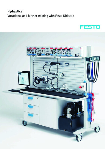
INTRODUCTIONTOHYDRAULICSPrinciples of HydraulicsIn general, the word “hydraulics” refers to power produced by movingliquids. Modern hydraulics is defined as the use of a confined liquid totransmit power, multiply force or produce motion.Though hydraulic power in the form of water wheels and other simpledevices have been in use for centuries, the principles of hydraulicsweren’t formulated into scientific law until the 17th century. It was thenthat French philosopher Blaise Pascal discovered that liquids cannot becompressed. Pascal’s Law states, “Pressure applied on a confined fluid istransmitted in all directions with equal force on all surfaces.”Generallyspeaking, theword “hydraulics”refers to powerproduced by themoving ofconfined liquids.To better understand Pascal’s Law, let’s use a bottle filled with liquid asan example. Let’s say the bottle has a one-square-inch opening. If wewere to apply 10 pounds of force on the cork at the opening, 10 poundsof force would be applied equally to all sides of the bottle. This isexpressed as 10 psi, or 10 pounds of force per square inch. 10 psirepresents the fluid pressure of the system.3Principles of Hydraulics
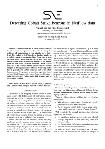
INTRODUCTIONTOHYDRAULICSThe Industrial RevolutionWhile well-understood in theory, Pascal’s Law wasn’t put into practicalapplication until the Industrial Revolution. A British mechanic namedJoseph Bramah built a hydraulic press using pressure, force and aconfined fluid in a lever-like system. A closed system, such as the onediagrammed here, provides a mechanical advantage similar to that of asimple lever.One pound of forceapplied to a onesquare-inch cylindercan balance 100pounds of force on a100-square-inchcylinder.Bramah discovered that, in a closed fluid system, a small force exerted ona small cylinder could balance a large force on a large cylinder. One poundof force applied to a one-square-inch cylinder can balance 100 pounds offorce on a 100-square-inch cylinder. In this way, we can move a 100-poundweight using only one pound of force.4The distance the 100 pounds will travel is inversely proportional to thedistance the applied force travels. So if we move a one-square-inchcylinder a distance of one inch, the 100-square-inch cylinder will move only1/100th of an inch.The Industrial Revolution
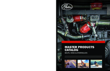
INTRODUCTIONTOHYDRAULICSKey Components of Hydraulic SystemsFluid - can be almost any liquid. The most common hydraulic fluids containspecially compounded petroleum oils that lubricate and protect the systemfrom corrosion.Reservoir - acts as a storehouse for the fluid and a heat dissipater.Hydraulic hose hasthe advantage oftransferring fluidusing lightweightcomponents andadds flexibilitywhen routingtransfer lines.Hydraulic Pump - converts the mechanical energy into hydraulic energy byforcing hydraulic fluid, under pressure, from the reservoir into the system.Hydraulic Valves - control pressure, direction and flow rate of thehydraulic fluid.Actuator - converts hydraulic energy into mechanical energy to do work.An actuator can be a rotary hydraulic motor or a hydraulic cylinder.Hydraulic motors and cylinders are used on agricultural, constructionand industrial equipment.Filter - removes unwanted contaminants from the fluid.Hose or Tubing Fluid Lines - transport hydraulic fluid from the pump throughthe hydraulic system.A pump’s functionis to convertmechanical energyinto hydraulicenergy by forcingfluid under pressureinto the system.ReservoirFilterLow Pressure ReturnFluid LinesPressuresurePresplySup er(Actuator)While there are different kinds of pumps, actuators, valves, etc., the basicdesign of a hydraulic system is essentially the same for all machinery.Key Components of Hydraulic Systems
INTRODUCTIONTOHYDRAULICSHydraulic SystemsTo understand how hydraulic systems work, it’simportant to understandnThe characteristics of fluidsnThe two types of hydraulic systemsnHydrodynamicsThere are two types of hydraulic systems, hydrostaticsystems and hydrodynamic systems.Hydrostatic systems use static confined liquids toperform work. Force is multiplied proportionately fromone confined container to another. A hydraulic jack is anexample of a hydrostatic system.Hydrodynamic systems use fluids in motion to perform work, using apump to transfer energy. The pump sets the fluid in motion which transfersenergy to a driven element. An example of a hydrodynamic systems is aback hoe.6In hydrodynamicsystems, fluidsflow. In theprocess, theycreate friction,which causes heatand a drop inpressure. Thesereduce systemefficiency.Hydraulic Systems
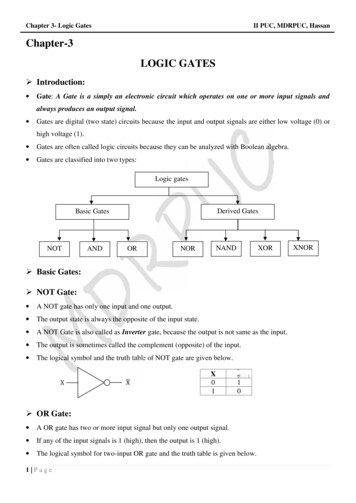
INTRODUCTIONTOHYDRAULICSHydraulic PrinciplesCharacteristics of FluidsFluids assumethe shape of theircontainer. Theyflow freely throughcomponents andaround corners.Both gases and liquids are fluids with one important difference betweenthem: Gases are highly compressible (as we find in A/C systems). Liquidsare not compressible.A fluid can be divided within a hydraulic system to perform multiple tasksat different speeds, all at the same time. For example, different diameterlines often branch off a simple manifold. Smaller diameter lines restrictthe flow of the fluid, thus speeding it up. Larger diameter lines slow theflow down. By controlling the rate of flow, we can provide the precise forceneeded to perform different tasks within the various parts of a hydraulicsystem.Hydraulic systems use liquids to transmit force. The word “hydraulics” comesfrom Greek, hydro, meaning “water,” and autos, meaning “pipe”. Familiarexamples of where you’d find hydraulics in use are in elevators, grease guns,airplane controls, construction equipment and automobile brakes.Main Valve1/4"5 GPM1/2"10 GPM3/4"15 GPM1 1/2"30 GPMA restriction in the line, such as a smaller IDhose, causes the fluid to flow more quickly.Larger ID hoses slow the flow down.7Hydraulic Principles
INTRODUCTIONTOHYDRAULICSFluid CharacteristicsHydraulic fluids can be almost any liquid. However, to maximize systemperformance, the following characteristics are important:Quality - The fluid should enhance system performance, provide longservice life and reduce maintenance.Viscosity - The viscosity of a fluid is its resistance to flow at a giventemperature. If it flows easily, its viscosity is low. If it flows with difficulty, itsviscosity is high. Temperature affects viscosity. Fluids at hightemperatures have lower viscosity and higher flow ability. Fluids at lowtemperatures have higher viscosity and lower flow ability. Choosing theproper viscosity assures the right flow for optimum system performance.Anti-foam - Aeration or foaming (that is, air in the system) can createsevere safety hazards and pump damage. Anti-foaming agents help preventfoaming and retention of air in the reservoir.Oxidation stability - This quality resists chemical breakdown and theresulting sludge buildup. Sludge, insoluble gums and varnish greatly reducefluid service life.Pour point - This is the lowest temperature at which a fluid will flow. Itshould be 20 F below the lowest expected temperature.Rust and corrosion prevention - Acids formed by the interaction of waterin hydraulic fluid can corrode metal components. Corrosion inhibitors eitherform a protective coating on surfaces or they neutralize acids as they form.Demulsifiers - These are additives that help the fluid reject theaccumulation of water. Water in the bottom of a reservoir could freeze incold weather and cause cavitation of the pump.Fire resistance - Fire-resistant fluids will not sustain combustion when anignition source is removed. Resistant fluids will not allow flame to flashback to the ignition source.8Hydraulic fluids havefour functions:1. Powertransmission2. System lubrication3. Heat dissipation4. Aerationprevention (notallowing outsideair to penetratethe system)Fluid Characteristics
INTRODUCTIONTOHYDRAULICSComponent CharacteristicsReservoirThe reservoir has four fluid-related functions. It1.2.3.4.Positivedisplacementpumps are eitherrotary orreciprocatingpumps.Provides storageMaintains cleanlinessMaintains temperatureRemoves airFor optimum system performance, reservoirs used in industrialapplications usually hold three times the fluid output of the pump. Thisallows the oil to cool before it re-enters the pump to once again be usedin the system.PumpMost pumps used in hydraulic systems are positive displacementpumps. There are two types, fixed and variable. Fixed displacement pumpsdeliver a constant rate of flow which cannot be adjusted. Variabledisplacement pumps have an adjustable rate of flow.Rotary pumps are either gear or vane pumps.Gear Pump CharacteristicsGear pumps develop flow by carrying fluid between the tooth spaces oftwo meshed gears. They are:9Component CharacteristicsnStrong, durablenFixed displacementnUsually louder than vane pumpsnHandle contamination betternLower cost
INTRODUCTIONTOHYDRAULIVane Pump CharacteristicsVane pumps use a slotted rotor, vanes and cam ring as pumpingelements. They are:nEither variable or fixed indeliverynRelatively quietnEasy to rebuildnSelf-adjusting to wearnNot as durable as gearpumpsHigh PressureLow PressureReciprocating Pump CharacteristicsReciprocating pumps draw fluid as the piston is retracted and then expel itas the piston moves forward. There are four types of reciprocating pumps:1. Radial piston2. Axial piston3. In-line4. Bent axis axial piston.All four pumps share the following characteristics. They:nAre long lastingnAre volumetrically efficientnAre expensivenHandle higher pressuresnHandle variable volume10Component CharacteristicsCS
ves controln Flow speedn Flow directionn Flow pressureInletDirectional control valves, including spool and rotary valves, can be twoway, three-way or four-way.Speed control valves include needle, globe,compensating and non-compensating valves.Pressure control valves include relief,regulator, sequence, counterbalance,holding and unloading valves.SystemPressureActuatorThe actuator converts hydraulic energyinto mechanical energy to do work.TankTypes of ActuatorsThe output of acylinder actuator is astraight line motionand/or force.Cylinder (linear) actuators - Theoutput of a cylinder is a straight linemotion and/or force. Cylinderactuators are used to lift weight,exert force, clamp, etc.Rotary (motor) actuators - The output of arotary actuator is a rotating force. Rotaryactuators are used to power pulleys, gears,rack-and-pinions, conveyors, drive axles, etc.Valves11
INTRODUCTIONTOHYDRAULICSFiltersThe most popular filters in hydraulic systems are surface filters.Filter RatingsFilters remove particles which are ratedin microns. For example, a filter rated at10 microns would trap at least oneparticle 10 microns or larger. Filterscommonly range from 3 - 35 micronsand are installed on:Surface FilternSuction linesnPressure linesnReturn linesFilters removeunwanted particlesfrom the fluid.LinesHydraulic fluids weretransferred in steel lines onearly hydraulic applications.But steel lines have definitedisadvantages compared tohose, which has become themost widely used means ofpower transmission in theworld. Hose offers distinctadvantages over metal pipeor tubes because hose:nIs highly resistant to rustnSupports high-pressurefluids and pressure impulsesnIs easy to route and installnAdds flexibility to moving partsnIs shock resistantnIs sturdynIs lightweightPhoto courtesy of Bobcat Company12Each hose is designed to meet the demands of its specific workingenvironment.The Gates Hydraulic system is a highly-engineered hose-and-connectorinterface that utilizes all components (hose, couplings, ferrules andcrimpers), designed to exceed industry standards.Lines transport thefluid from thepump through thehydraulic system.The lines can berigid metal pipe,tubes or flexiblehose assemblies.Filters
INTRODUThe use of hydraulicmachinery gainedacceptance in the early1940s. Engineers discoveredthat lightweight hydraulicsystems needed onlyminimal space to producehigh-powered output. Further,these self-lubricatingsystems protected the metalpipe and tube conductorsfrom rusting.Eventually, hydraulic hosereplaced the metal pipe andtube conductors of thoseearly systems. Rust-resistanthoses were easier to routeand install, and they addedflexibility to moving parts.Hoses also absorbed theshock and vibration thattypically broke the metaltube conductors. In addition,hose withstood the constantimpulse (many times persecond) of the hydraulicpumps that were pushingfluid throughout the system.Today, hydraulic hose is themost widely used means ofpower transmission in theworld. Farm machinery,trucks, busses and all typesof earth moving equipmentuse hydraulic hoses.CTIONTOHYDRAULICSWhy Hydraulic Hose?Oil & Gas DrillingOil & Gas Drilling RigsAgricultural EquipmentCombines/HarvestersMidsize to Large TractorsLawn & Garden TractorsConstruction EquipmentHauler t TrucksScrapersBackhoesMining Equipment13Dozers/CrawlersManufacturingHauler TrucksMaintenance, Repair, OperationsMachine ToolsInjection MoldersPressesRoof SupportsWhy Hydraulic Hose?Fork LiftsExcavators
INTRODUCTIONTOHYDRAULICBasics of HoseThe wide range of hydraulic applications calls for hydraulic hose of differentsizes, capabilities and constructions. Most hydraulic hoses are built tostandards, such as Society of Automotive Engineers (SAE), European Norm(EN), and International Standards Organization (ISO), which set generalguidelines regarding construction, tolerances and minimum performanceratings, among others. However, these ratings do not guarantee that allproducts meeting one standard are exactly the same.Manufacturing tolerances vary from manufacturer to manufacturer but staywithin international standards. For that reason, Gates recommends nevermixing and matching manufacturing products from different manufacturerswhen making a hydraulic assembly.There are additional standards set by such government agencies as the:nMine Safety and Heath Administration (MSHA), which setsspecifications for flame resistancenCoast Guard (USCG), which determines suitability for marine vesselusagenDepartment of Transportation Federal Motor Vehicle Safety Standards(DOT/FMVSS), which sets requirements for hydraulic, air and vacuumbrake hose, hose assemblies and hose end fittings for use onpassenger cars, trucks, busses, trailers and motorcyclesSAE, EN andISO specificationsset specificrequirementsconcerning size,tolerances andminimumperformancecharacteristicsfor each majorhose type.14Basics of HoseS
INTRODUCTIONTOHYDRAULICSHydraulic Hose ConstructionThere are three major components within all hydraulic hoses. Each hoseconsists of a tube, reinforcement and cover.Tube:The tube must be specially compounded to chemically resist any adverseeffects of the fluid flowing through it. It must also be resistant tocorrosion, deterioration and the effects of temperature extremes.The inside diameter(ID) of the tube is thekey measurement ofhose size.The reinforcement isthe muscle of allhydraulic hoses andit determinesworking pressure.Gates has a line ofabrasion-resistanthoses that lastslonger thanstandard rubbercover hoses.The inside diameter (ID) of the tube is the key measurement ofhose size. It must provide the proper volume of fluid for the specificapplication. For an SAE specification hose, the smaller the ID of the tube,the higher the pressure it can handle.Reinforcement:The reinforcement is the muscle of all hydraulic hoses; it determines theworking pressure of the hose. It is either a braid or a spiral wrap and ismade from natural fibers, synthetic materials or wire. Some hoses have areinforcement that is a combination of fiber and wire, or multiple layers ofwire braids or spiral layers.Cover:The cover protects the tube and reinforcement from heat, abrasion,corrosion and environmental deterioration. It can be made from syntheticrubber, fiber braids or a combination of both.Synthetic rubber covers are more resistant to abrasion than textile-braidcovers. Gates MegaTuff and XtraTuff hoses are extremely abrasionresistant and last longer than standard hoses with rubber covers.Textile-braid covers are preferred when gases are present becausegases migrating through the hose will not cause a textile-braid cover toblister or separate from the tube. However, textile-braid covers can trap oil,dirt and other contaminants which shorten hose life.NOTE: The types of materials used in the tube, reinforcement and coverwill be discussed in a later training module.15Hydraulic Hose Construction
INTRODUCTIONTOHYDRAULICTypes of Hose by Operating PressureHydraulic hose can be grouped by their operating pressure at a givenID from “extremely high” to “low”. For example, the very-high-pressurehose, 32C12, a hose with a 2” ID, has an operating pressure of 2500 psi.In contrast, a 3/8” ID hose, such as G1, has a operating pressure of2600 psi, yet is considered a medium pressure hose. In general, thelarger the hose ID, the lower the operating pressure.This grouping of hose by pressure rating is confusing. For now, it is enoughfor you to know only that such a rating system exists. We’ll discuss hoseselection and pressure ratings in a later training module.Extremely High and Very High Pressure HoseVery-high and extremely-high pressure hoses perform best on applicationsthat are subject to extreme high impulse (or pressure surges) such as offhighway equipment and heavy-duty machinery, for example. These hosesare reinforced with four or six layers of spiraled, high-tensile steel wire overa layer of yarn braid. Again, we’ll discuss the specifics of hose materials ina later training module.The rated workingpressure of ahydraulic hose isthe maximumpressure at whichthe hose is to beused. It is not to beexceeded in anyapplication.16Types of Hose by Operating PressureS
INTRODUCTIONTOHYDRAULICSHigh-Pressure HoseReinforced with two steel wire braids, these are often called “two-wire”braid hoses. You’ll find them in high-pressure applications, such as onconstruction equipment. They range in operating pressures from 6000 psi(3/16” ID) to 1825 psi (2” ID).Medium-Pressure HoseOperating at pressures from 3000 psi to 300 psi, these hoses can haveone-wire, multiple-wire and/or textile-braid construction.Burst pressureis not a workingpressure rating.It is a safetyvalue to coverpressure surges.17Types of Hose by Operating Pressure
INTRODUCTIONTOHYDRAULICMedium-pressure hoses often find application on heavy-duty truck andfleet vehicles. In the 1940s, there were no flexible hoses designedespecially for the fleet user. However, truck mechanics found an aircrafthose that met the demands of fleet applications. Soon, this aircraft hosereplaced the rigid copper tubing originally used on trucks. This truck hoseis often called, “flexline,” or “TWT” (textile-wire-textile). The Gates name isC5 (SAE 100R5).18Types of Hose by Operating PressureS
INTRODUCTIONTOHYDRAULICSSpecialty HoseFleet and Air Brake System HosesSuction returnhoses must berated forvacuum. Lookfor the In. Hg(Inches ofMercury) value.Low-Pressure HoseYou’ll find these hoses in applications with operating pressures under 300psi. Typically, they’re used to transmit petroleum-based fluids, lubricatingoil, air, glycol anti-freeze and water. Gates GMV hose is also rated forsuction applications.19Types of Hose by Operating Pressure
INTRODUCTIONTOHYDRAULICSSpecialty HoseMany hoses don’t fit easily into a particular pressure category. Thesespecial application hoses are used to convey such things as refrigerant orLP gas. They are capable of operating at temperature extremes and inthose applications requiring non-conductivity of electricity.20GT7NC and GT8NCthermoplastic hoseshave the samepressure rating asSAE 100R1 and SAE100R2 hoses,respectively.However, they arequite different inconstruction to meetspecial applicationneeds (lighterweight, very longlengths and nonconductivity).Types of Hose by Operating Pressure
INTRODUCTIONTOHYDRAULICSAutomotive HosesPower Steering HoseIn addition to a complete line of power steering assemblies, Gatesmanufactures hoses for power steering pressure and return lines.Using PS188 hose and couplings, you can custom fabricate power steeringassemblies using your Gates crimping equipment.Air Conditioning and Refrigeration Systems HosePolarSeal Barrier Refrigerant HoseUsed in automobile A/C systems, as well as industrial A/C systems (suchas tractors, trucks and both mobile and stationary refrigeration units),PolarSeal hose minimizes the permeation of R134A and R12 refrigerants.21Types of Hose by Operating Pressure
INTRODUCTIONTOHYDRAULICSHose Nomenclature12 EF G 5K5000 psi ratingGlobalEnvironmentally FriendlyDash size (3/4” I.D.)8M2 TThin cover2 WireMegaSys (1/2 SAE bend radius)Dash size (1/2" I.D.)Dash SizesThe inside diameter (ID) of a hydraulic hose determines its size. This IDsize is expressed as a Dash Number, which is the number of 1/16”segments to equal the hose ID. For example, a 1/4” ID hose has 4 1/16”segments for a dash size of -4. A 1/2” ID hose (8/16”) has a dash sizeof -8. A hose with a 2” ID has a dash size of -32.NOTE: The dash size always precedes the Gates nomenclature, as you seein the illustration above (8 dash size M2T the Gates name).However, there are exceptions.8C5C22“Cotton” coverSAE 100R5 SpecsDash size (13/32" I.D.)Hoses designed to replace tubing are the exceptions to this dashsize classification. Tubing is measured by its outside diameter (OD).For example, a 1/2” OD tube has an inside diameter (ID) of 13/32”.The -8 hose replacement for this tubing has a 13/32” ID, but it is stillcalled -8, the equivalent of 1/2” tube OD.Hose I.D. (Inches)All Except,C5 Series,C5 SeriesC14 andC14 and AC134aAC134aDash No.In.mmIn. 150.857.663.576.288.9101.6----3/16 4.81/4 6.45/16 7.913/32 10.31/2 12.75/8 15.9--7/8 22.21-1/8 28.61-3/8 34.91-13/16 46.0--2-3/8 60.3-------Dash size exceptions in the Gates line are C5, PolarSeal andC14 (PTFE).Types of Hose by Operating Pressure
INTRODUCTIONTOHYDRAULICSBasics of CouplingsCouplings, or“fittings,” are themetal componentsthat are teamed withhose to makehydraulic hoseassemblies.Couplings attach the hose to the equipment. They’re also the metalcomponents of any hydraulic hose assembly. The stem end of thecoupling connects to the hose, while the thread end (or couplingtermination) of the coupling attaches to the equipment. All Gatesdescriptions of couplings put the hose end first, followed by thethread end.Field-Attachable CouplingsHigher pressure hoses can use field-attachable (also called “reusable”)couplings, as well as permanent couplings. You can fit field-attachablecouplings right on the hose using only a wrench and a vise. No specialequipment is required. While handy, they do cost more than permanentcouplings and take more time to attach.23Basics of Couplings
INTRODUCTIONTOHYDRAULICSPermanent CouplingsYou need crimping or swaging equipment (sometimes both) to puta permanent coupling on a hose. Permanent couplings can bepre-assembled (“one piece”), such as our MegaCrimp couplings.One-piece couplings have the ferrule permanently attached to the stem.Gates also offers two-piece couplings, which consist of a ferrule andseparate stem. Gates GlobalSpiral GS spiral wire couplings are agood example.MegaCrimp CouplingWire ReinforcementPermanent couplingsare generally morereliable, easierand quicker to attachthan field-attachablecouplings, whichmakes them themost popularcouplings in use.Serration “biting” the wireGlobal Spiral CouplingStem24FerruleGates descriptionsalways list stemend first.For example,8G-8MPStem End (8G) Thread End (8MP)Basics of Couplings
INTRODUCTIONTOHYDRAULICSCoupling Thread Types and SealsThere are three types of coupling interfaces used in hydraulics today: ThreadInterface, Mated Angle, and O-Ring.Interference SealThreaded couplings have two types of threads: Male (outside threads) andFemale (inside threads).FemaleMaleNational Pipe Tapered FuelThere are two types of threads. The first, the National Pipe Tapered forFuel (NPTF) has, as the name implies, a tapered thread. When the maleand female components are threaded together, the tapered threadsdeform, applying pressure on one another, and thus making a tight seal.Threads and sealingsurfaces conform toone of many industrystandards. A few ofthe more commonNorth Americanthread end types areintroduced here. In alater trainingmodule, we’ll studyinternationalthreads.Basics of CouplingsNPTF25
INTRODUCTIONTOHYDRAULICSMated Angle SealsHere, the seal is made when the male and female threads are screwedtogether. Two types of mated angle seals are SAE 45 and JIC 37 , butthere are others. The NPSM seal is a mated angle.National Pipe Straight MechanicalNational Pipe Straight Thread Mechanical Joint (NPSM) brings two 30 tapered seats together to make the seal.SAE 45 flare couplings are used on lower pressure applications, such asfuel lines, hot oil lines or refrigerant lines. A “rule of thumb” states thatthey are also used in “under the hood” and in marine applications.JIC 37 angle seats are used on medium-pressure and high-pressure lineson heavy equipment to join hydraulic hose assemblies to hydraulicsystem components.30 Couplings with angleseats for sealinghave straight orparallel threads. Thethreads themselvesdo not seal fluids aswith taperedthreads. Instead, thethreads function tomechanically bringthe two mating angleseats together.NPSM37 45 JIC 37 SAE 45 26Basics of Couplings
INTRODUCTIONTOHYDRAULICSO-Ring SealsThere are three types of O-Ring seal designs:O-Ring BossFlat-Face O-Ring SealO-Ring FlangeGates provides toolsfor measuring andidentifying the manydifferent types ofthread ends on themarket. These toolscome in a handyPocket Kit (Part No.86583/Product No.7369-4318) thatincludes a threadspecification bookletwith the variousshapes andmeasurementsnecessaryfor properidentification.BulkheadPortO-Ring“O” Ring BossIn the Boss design, straight threads make the connection while a rubber“O” makes the seal. Threads pull the O-ring against the port, which has amachined groove for the O-ring, flattening the O-ring and making a sealthat is excellent for high-pressure applications.O-Ring Face Seal MaleO-Ring Face Seal Swivel FemalePortO-Ring GrooveFlat Face for O-Ring SealIn the Flat-Face O-Ring Seal (FFOR), the O-ring sits in a groove on the male’sface. The seal is made when the O-ring of the male meets and flat face of thefemale. The solid male O-ring face seal fitting will mate only with a swivelfemale O-ring face seal fitting.O-Ring FlangeO-RingStem27BulkheadO-Ring Flanges make high-pressure, large-diameter connections. A port isbored with a center outlet, surrounded by a smooth flat face which has fourtapped holes and four mounting bolts that tighten down onto flange clamps.There are no threads on this coupling. The flange itself has the groove forthe O-ring.Basics of Couplings
INTRODUCTIONTOHYDRAULICHydraulic Crimping EquipmentGates offers five crimpers you can use to make factory-quality assembliesin the field.Power Crimp 707Our most popular and versatile crimper, the PC 707crimps four-wire hoses from 3/16” to 1-1/4” I.D. Forstationary applications and operating on either 115vor 220v, it can be modified to act as a swager. Thebottom load PC707 and digital readout allows theoperation to make factory-quality assemblies quicklyand easily.Different die setsare required,depending on thetype and size of thehose and thecouplings to beattached. Alwaysrefer to the crimpdata manual(428-7365).MobileCrimp 4-20This lightweight (58 lbs) portable crimper can handle1-1/4” I.D. four-wire hose. It’s perfect for use onservice trucks or where electrical power is not readilyavailable. Highly adaptable, the MC 4-20 operates onair pressure, AC or DC – even a hand pump. Availablein either Positive Stop or Digital Dial models.GC32-XD Crimper28The first global crimper, the GC32-XDautomatically converts any electrical inputvoltage greater than 208 volts to 220 volts(single phase). Quickly and easily makeshydraulic assemblies from Gates entire hoseand coupling product line. Adjustable tooperator height and reach. Includes colorcoded die sets stored in see-throughpolypropolene tubs, a Quick Change Tool tomake loading dies easy, and optional depthstop, plus other features to
In general, the word "hydraulics" refers to power produced by moving liquids. Modern hydraulics is defined as the use of a confined liquid to transmit power, multiply force or produce motion. Though hydraulic power in the form of water wheels and other simple devices have been in use for centuries, the principles of hydraulics