Transcription
Mini SplitTECH MANUALWINE CELLARINTERNATIOExclusive dealer ofNAL
We manufacture, test and certify 100% of our wine cooling units inthe USA. By sourcing the best components and closely controlling ourmanufacturing processes, we can assure the highest-quality, lowestdefect manufacturing rates in the industry.Copyright 2012. WhisperKOOL. All rights reserved.This manual, the product design, and the design concepts are copyrighted by WhisperKOOL, with all rights reserved. Your rightswith regard to the hardware and manual are subject to the restrictions and limitations imposed by the copyright laws of theUnited States of America. Under copyright laws, this manual may not be copied, reproduced, translated, transmitted, or reducedto any printed or electronic medium or to any machine-readable form, for any purpose, in whole or in part, without the writtenconsent of WhisperKOOL.or clerical errors.WhisperKOOL reserves the right to make corrections or improvements to the information provided and to the related hardwareat any time, without notice.Vinothèque and WhisperKOOL are registered trademarks, and ECE is a trademark of WhisperKOOL. All rights reserved.Mention of third-party products is for informational purposes only and constitutes neither an endorsement nor arecommendation. WhisperKOOL assumes no liability with regard to the performance or use of these products.03.14.13MPS 031413
TABLE OF CONTENTSQuick Reference GuideSystem . . . . . . . . . . . . . . . . . . . . . . . . . . . . . . . . . . . . . . . . . . . . . . . . . .2. . . . . . . . . . . . . . . . . . . . . . . .3Introduction . . . . . . . . . . . . . . . . . . . . . . . . . . . . . . . . . . . . . . . . . . . . . . . .4Receiving & Inspecting The System . . . . . . . . . . . . . . . . . . . . . . . . .5Before You Start . . . . . . . . . . . . . . . . . . . . . . . . . . . . . . . . . . . . . . . . . . . .6Preparing the Wine Cellar. . . . . . . . . . . . . . . . . . . . . . . . . . . . . . . . . . .7Mini Split Evaporator Unit Internal Quick Reference Guide .10Preparing & Installing the Evaporator Unit (Fan Coil Unit) . .11Installing the Evaporator Unit (Fan Coil Unit) . . . . . . . . . . . . . . .13Mini-Split Evaporator Unit (Fan Coil Unit) Terminal Board . .17Preparing the Condensing Unit . . . . . . . . . . . . . . . . . . . . . . . . . . . . .18Mini-Split Condenser Wiring Diagram . . . . . . . . . . . . . . . . . . . . . .19Line Set Diagram . . . . . . . . . . . . . . . . . . . . . . . . . . . . . . . . . . . . . . . . . . .22Installing the Condensing Unit . . . . . . . . . . . . . . . . . . . . . . . . . . . . .23System Operation. . . . . . . . . . . . . . . . . . . . . . . . . . . . . . . . . . . . . . . . . . .26Controller Functions . . . . . . . . . . . . . . . . . . . . . . . . . . . . . . . . . . . . . . . .27Troubleshooting Guide . . . . . . . . . . . . . . . . . . . . . . . . . . . . . . . . . . . . .30Technical Assistance & Accessories . . . . . . . . . . . . . . . . . . . . . . . . .32WhisperKOOL requires that ainstall, Pipe, Evacuate, Charge, Start and Test all split systems.proper installation of the system.Read, understand and comply with the unit’s installation manual, and piping diagrams.www.whisperkool.com Page 1
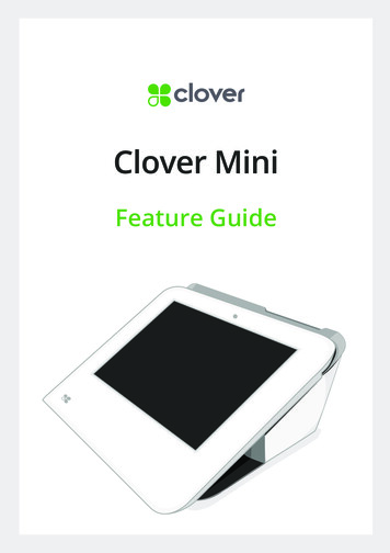
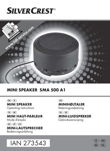
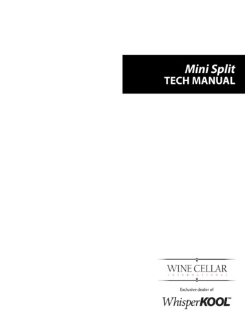
QUICK REFERENCE GUIDEWall Mounted Mini Split Evaporator Unit (Fan Coil Unit) Front / Side ViewEvaporator Unit (Fan Coil Unit) FControllerFilter GrilleEvaporator Unit (Fan Coil Unit) Rear / Side ViewMounting Key Hole (X4)THROUGH THE WALLOption 1Knock Out For WiringKnock Out For Suction LineKnock Out For Liquid LineKnock Out For Drain LineCircular ConnectionMounting LocationINSIDE CELLAROption 2Knock Out For Suction LineKnock Out For Liquid LineKnock Out For Drain LineKnock Out For WiringPage 2 1-800-343-9463MPS 031413
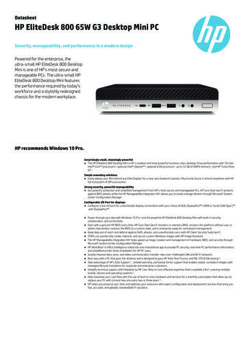
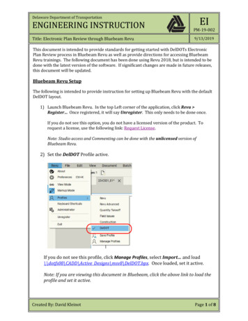
QUICK REFERENCE GUIDEController LayoutNote:Refer to page 27 for complete listing of buttons and symbols.CompressorEvaporator FanCellar “Pre-Chill” Bu on 3-5Energy Reduc onBu on 1Energ FHiTemp History &Scroll Bu on 1LowTemp History &Scroll Bu on 1Set Bu on View Set Point 1 Change Set Point 3-5 SET Down CPSM 3-5 Reset Hi & Lo Bu on 3-5Control “ON/OFF” Bu on Turns the Evaporator Unit(Fan Coil Unit) “ON/OFF” 1ALARMPre-Chill DisplayPLATINUM MINI-SPLIT SPECIFICATIONSModelMini Evaporator Unit(Fan Coil Unit)Cellar Size (cu. ft.)500Dimensions20”w x 10.5”h x 11.25”dBTUh with 90 air enteringthe condenser coil.154094CFMRefrigerantR-134aCondensing Unit HP1/5Mini Condenser11.5”w x 9.9”h x 16”d190Voltage Rating (20 amp 115V or 230V - 20 amp dedicated circuit requireddedicated circuit required)Weight (lbs)25AMPS (Starting/Running)2/1dBA514111/3.865Line SetSuction Line 3/8” od. Liquid Line 1/4” odDrainline1/2”InstallationThermostatTemp. DeltaWarrantyEvaporator Unit (Fan Coil Unit) is installed in the cellar. The Condensing Unit is installed up to 100Digital Control Display(maintains proper cellar temperature when exhaust environment does not exceed 110 F)2 year parts and laborwww.whisperkool.com Page 3
INTRODUCTIONCustomer ServiceThank you for purchasing a WhisperKOOL cooling system. We strive to provide the highest quality products and thebest possible customer service. If you have any questions about your system, please call us at 1-800-343-9463 or visitWhisperKOOL.com.Using the ManualThis Owners Manual is intended to assist in the proper maintenance of the cooling system. In order to ensure thelongevity of your cooling unit, the equipment should be installed as outlined in the Technician’s Manual. It is also vitalto establish a proper care and maintenance schedule. Please read and review this manual carefully and keep it forfuture reference.What Is the WhisperKOOL Cooling System?The WhisperKOOL cooling system is a specialized refrigeration system designed for one purpose only: to maintainproduces minimal in-cellar noise and has the most lenient exhaust requirements. An exterior housing is required foroutdoor condensing unit installations.How Does the Cooling System Work?Similar to the air conditioning systems used for homes, the Evaporator Unit (Fan Coil Unit) and Condensing unitsare installed in separate locations and are connected by a refrigerant line set. The evaporator portion is commonlyinstalled in the wine cellar, with the condensing unit located either outside or in a remote indoor location that isventilated. An exterior housing is required for outdoor condensing unit installations.Temperature SettingThe WhisperKOOL system can be set at any temperature within the acceptable wine-aging range of 45 F to 67 F. Itis designed to cool up to 55 F cooler than the ambient temperature of the space to which the condensing unit isinstalled.WARRANTY REGISTRATIONinstalling your system and submit via mail, fax, or e-mail.Mail to:WhisperKOOLATTN: Warranty Registration1738 E. Alpine AvenueStockton, CA 95205-2505USAPage 4 1-800-343-9463Fax to:209.466.4606ORScan and email to:warranty@whisperkool.comORMPS 031413
RECEIVING & INSPECTING THE SYSTEMReceiving and Inspecting the System Lift only at the designated hand hold locations on the shipping container or fully support the unit from underneath. A shipment may include one or more boxes containing accessories.Before opening the container, inspect the packaging for any obvious signs of damage or mishandling.Write any discrepancy or visual damage on the Bill of Lading before signing.Allow the condensing unit to sit 24 hours prior to start up. The Condensing Unit can be placed in theinstallation location, piped and evacuated during this time.Note: WhisperKOOL units are manufactured in the USA and tested prior to shipment.Review the Packing Slip to Verify Contents Check the model number to ensure it is correct. Check that all factory options ordered are listed.If any items listed on the packing slip do not match your order information,contact WhisperKOOL Customer Service immediately.Check the Box for the following contents:Main Evaporator Box F(1) 12 Foot Bottle Probe(4) 2” #8 Hex Head Screws(1) 10 FT. 1/2”Drain Line(1) ¼” Sight Glass(1) ¼” Filter Drier(1) Power Cord Strain Relief (locatedinside the Evaporator Unit)(1) Split System Warranty Checklist(1) 10” Piece of Cork Tape(1) Split System Owner’s Manual(1) Split System Tech Manual(1) Evaporator Mounting Template(1) Platinum Mini Split Evaporator Unit ( Fan Coil Unit)Main Condensing Unit Box:(1) Condensing UnitPlease leave the unit in its original box until you are ready for installation. This will allow you to move the productsafely without damaging it. When you are ready to remove the product from the box, refer to the installationinstructions.TIP: Save your box and all packaging materials. They provide the only safe means of transporting/shipping the unit.www.whisperkool.com Page 5
BEFORE YOU START1. Inspect all components prior to installation. If damage is found, please contact your distributor or WhisperKOOLCustomer Service at 1.800.343.9463.2. The Condensing Unit requires a dedicated 115-volt 20-amp circuit. Use a surge protector with the unit. Do notuse a GFI (Ground Fault Interrupter) line.3. It is REQUIRED to install a drain line to remove condensation from the Evaporator Unit (Fan Coil Unit).4. The system is intended for use in properly designed and constructed wine cellars. Hire a professional winestorage consultant with a valid contractor’s license to build your wine cellar.5. WhisperKOOL requires that all Split Systems are installed by a certified HVAC-R technician only, Nate or equivalent isrecommended.6. Warranty is not active until a Warranty Checklist has been received, reviewed, and approved.If you encounter a problem with your WhisperKOOL system, please refer to the Troubleshooting Guide on page 16.If you have any further questions, concerns, or need assistance, please contact WhisperKOOL’s Customer Service at1.800.343.9463. Please be sure all testing has been completed prior to contacting Customer Service. Please have yourresults ready for your representative.Page 6 1-800-343-9463MPS 031413
PREPARING THE WINE CELLARThe performance and life of your system is contingent upon thesteps you take in preparing the wine cellar.Note: Improperly preparing your enclosure or incorrectly installing yourIT IS HIGHLY RECOMMENDED THAT YOU OBTAIN THE ASSISTANCEOF A WINE STORAGE PROFESSIONAL.Wine storage professionals work with licensed contractors, refrigeration technicians, and racking companies to buildwell-insulated, beautiful, and protective wine cellars. WhisperKOOL has put together some useful tips to assist in theinstallation process. Our recommendations are meant to act as a guide in the process of building a proper enclosure.Wall & Ceiling FramingBuild wine cellar walls using standard 2x4 or 2x6 construction methods and ceiling joists following the guidelines oflocal and state codes in your area. As a general rule, the thicker the walls and the higher the insulation value in yourcellar, the better it will be at maintaining a consistent temperature.InsulationInsulation is REQUIREDnormally used in cellar construction or, in some cases, “blown-in” insulation is used. It is very important that all wallsand ceilings are insulated to keep the cellar temperature as consistent as possible during the summer and wintermonths. The R-value, or quality of insulation, is determined by the rate at which heat passes through the insulation.The higher the R-value, the more resistant the insulation is to conducting heat. Using higher R-values in insulation willlower your operating costs and unit run time. (R-13 minimum, R-19 recommended, R-30 for ceiling and exterior walls.)Vapor BarrierWater vapor creates its own pressure, separate from the air pressure, and will intrude into colder/drier areas. A vaporbarrier is REQUIRED to prevent the intrusion of water vapor so that the cellar can be kept at the correct temperatureand humidity. 6 mm plastic sheeting (recommended) should be applied to the warm side of the cellar walls. Thevapor barrier must also be applied to the outside walls and ceiling. If it is impossible to reach the outside, then theplastic must be applied from within the cellar. The most common method is to wrap the entire interior, leaving theplastic loose in the stud cavity so the insulation can be placed between each stud. All of the walls and ceiling must bewrapped in plastic for a complete vapor barrier.air. The moist air can cause mold to form, and standing water in drain pans promote microbial and fungal growth thatcause unpleasant odors and indoor air quality problems. If mold is found, remove it immediately and sanitize thatAny break in the vapor barriers (cut, nail hole, over-lapping, etc) will allow a moisture leak and must be sealed. Electricconduit is a “duct” for vapor to travel in. The conduit should be caulked and sealed on the warm air end.STARCUCOFAwww.whisperkool.com Page 7
Unobstructed airflow to and from the Evaporator Unit (Fan Coil Unit) and Condensing Unit is critical for theoverall performance and life-span. A minimum three-foot clearance (five foot is ideal) area is crucial. The air the fansblow needs to circulate and either dissipate or absorb heat from the space, the more air to exchange the more efficientthe system will operate.Note: Avoid attempting to camouflage the unit. This will restrict airflow and thus the systems ability to workefficiently.Keep ClearWine CellarMounting the Evaporator Unit (Fan Coil Unit)The Evaporator Unit (Fan Coil Unit) must be mounted within 18“ of the top of the room in order to achieveroom will contribute to consistently cool environment by capturing the warm air and replacing it with cool air.Mounting the unit low in the room will result in a temperature variation in the room due to the unit’s inability toDoor and Door SealAn exterior grade (1 3/4”) door must be installed as a cellardoor. It is essential that weather stripping is attached toall 4 sides of the doorjamb. A bottom “sweep” or thresholdis also required. The door must have a very good vaporseal to prevent warmer moist air from leaking into thecellar. One of the most common problems with coolingsystems running continually is due to the door not sealingproperly. In cases where glass doors are used and theroom size is close to the recommended system size,the next larger size WhisperKOOL system should beused. This will compensate for the insulation loss due tothe lower insulating rating of glass.Page 8 1-800-343-9463MPS 031413
VentilationThe necessity of dissipating heat away from the condensing unit is critical to the performance and cannot beoverstated. As the system operates and cools, a greater amount of heat is generated on the condensing side of thesystem. Adequate ventilation is required in order to dissipate heat away from the condensing unit. If ventilation ismay be advisable to install a vent fan to dissipate heat within the exhaust area on the condensing side of the system.However, you must have a fresh air inlet as well.Note: If you are unsure about having adequate ventilation in your install location, pleaseEvaporator Unit( Fan Coil Unit)BACK - EXHAUST SIDEFRONT - WINE CELLARCondensing UnitExterior Cellar WallAmbient Temperature Factorarea that it is exhausting to does not exceed 110 F. Therefore, you want to exhaust the condensing unit in a space whichwill not exceed 110 F. Otherwise the system will not have the capacity to keep the wine at a desirable 55 F.Warning, allowing your system to operate in high ambient temperatures forextended periods of time will greatly decrease the life of your system and voidyour warranty. The cooler the temperature of the air entering the condenser coilthe more cooling capacity the system has. The less heat gain through the commonwall, the less the electricity consumption.www.whisperkool.com Page 9
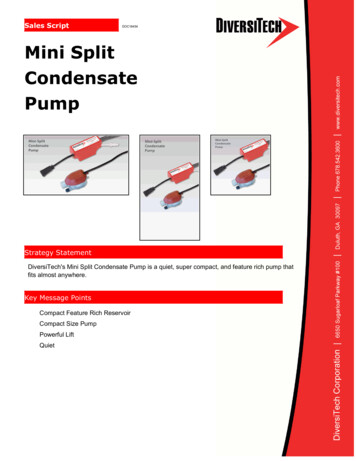
MINI SPLIT EVAPORATOR UNIT INTERNAL QUICK REFERENCE GUIDEPANASONICBLOWERSOLENOID VALVESOLENOID COILTXVPage 10 1-800-343-9463TXV SENSINGBULBMPS 031413
PREPARING AND INSTALLING THEEVAPORATOR UNIT (FAN COIL UNIT)Required Tools: Drill5/32” Drill Bit1/4” Socket Drill Bit 1/4” Wrench Phillips Head Screwdriver Tape Measure Brazing TorchDrywall SawLadder LevelPliersPencil FDRAIN PAN1.Detach the Access Panel by removing the2. Unscrew the nut attached to the CircularConnector (Bottle Probe Input.)3. Install the Circlar Connector (Bottle ProbeInput) in The hole located at the bottom of thehousing.HOLE FOR CIRCULAR CONNECTOR(BOTTLE PROBE INPUT)CIRCULAR CONNECTOR/BOTTLE PROBE INPUTNOTE: From a frontal perspective, the CircularConnector is located in the rear-left corner of thebottom of the unit.RUBBER WASHERUNIT PANEL4. Secure the Circular Connector (Bottle ProbeInput) to the unit using the provided nut (theRubber Washer should remain inside the unit).NUTwww.whisperkool.com Page 11
PREPARING AND INSTALLING THEEVAPORATOR UNIT (FAN COIL UNIT)Length To Extend To Desired Tee Location3”5. Cut the supplied Drain Tubing at a length long enough to extend from the Drain Pan to the desired BarbedTee location and a second piece 3 inches long.Power3/8” Suction1/4” LiquidDrainPage 12 1-800-343-94636. Depending on the desired installation, remove the rearor bottom knockouts for the Line Set, Drain Line and PowerCord.7. Using a 5/32” Drill Bit on a drill, from the outside of theunit cut holes through the unit’s insulation for the line setand drain line.MPS 031413
INSTALLING THE EVAPORATOR UNIT (FAN COIL UNIT)Note: The evaporator is designed to be mounted on two standard 16” spaced wall studs.1. Locate two desired wall studs. Mark center lines for the studs vertically on the wall (16 inches apart)followed by a level horizontal line at your desired height.Note: The top of the unit needs to be installed at aminimum of 6 inches from the ceiling and no furtherthan 18 inches from the ceiling.2. Place the installation template on the wall lining upthe vertical lines through the sight slots.3. Mark through the indicated Mounting Screw holesand location for the Access Hole.4. Set Installation Template aside.1/16”WALLSTUD5. Install the supplied four 2” #8Hex Head Screws into the markedmounting screw locations leaving 1/6”between the wall surface and screwhead.6. Cut out the Access Hole using a drywall saw or desired method. Be sureto clear all debris and insulation.7. The wall is now ready for installation. Place the prepared unit below theinstall location.Note: During installation WhisperKOOL recommendselevating the unit close to the install height.8. Raise the evaporator to the installation location. Align the rear key holeswith the mounting screws and mount the unit. Fwww.whisperkool.com Page 13
INSTALLING THE EVAPORATOR UNIT (FAN COIL UNIT)9. Using a 1/4” wrench or socket tighten accessiblemounting screws inside of the unit.10. Remove the Line Set Caps followed byrouting the 3/8” suction line and 1/4” liquid lineinto the unit and braze.Note:electrical and insulation while brazing inside ofthe unit.11. Route power supply wires into the unit throughthe power knockout and install the supplied strainrelief.12. Connect power supply wires to the pre-installedbutt splice connectors located inside of the unit(Hot Black, Neutral White, Ground Green).Page 14 1-800-343-9463MPS 031413
INSTALLING THE EVAPORATOR UNIT (FAN COIL UNIT): DRAIN LINECondensation Drain LineThe condensation drain line tube is used to remove excess condensation from the Evaporator Unit ( Fan Coil Unit) to aproper discharge location. It is important that the drain line tube is properly connected and used to prevent leakageand other problems associated with excess condensation.Failure to use the condensation drain line tube will void the warranty on the unit.Drain LineAll systems come with a drain line for additional removal of excessive condensate. It is mandatory to install thedrain line whether it leads through the wall and out of the cellar or remains inside the cellar. During operation, thecooling system will strip excess water from the air in order to maintain the proper level of humidity within the cellar.However in extreme humidity, additional condensate will be removed. Thus the drain line will prevent overflow andleaking by allowing for discharge of the additional condensate.Insert the middle barb of the barbed tee THROUGH THE WALL DRAIN LINEfitting into to the end of the drain lineOPTION 1coming from the evaporator. Rotate fittingso tee is in the orientation shown in theNOTE: The fitting should bediagram on the left. Connect the three inchplaced vertical with the threepiece to the barb on top. Connect theinch cut out facing up.remaining “long” piece of drain tubing tothe bottom barb of the tee.NOTE: The fitting should be placed verticalwith the three inch cut out facing up.INSIDE CELLAR DRAIN LINEOPTION 2 FWRONG: Drain line is under water.Failure to install the drain linevoids the warranty.3”CELLAR WALLWALL MOUNT CLAMPTo prevent mold from growing,allow the drain line to hangabove the water line.www.whisperkool.com Page 15
INSTALLING THE EVAPORATOR UNIT (FAN COIL UNIT) F13. Connect the Bottle Probe.14. Reinstall the access panel removed in step 1 of Evaporator Preparation.15. Plug in the evaporator.Page 16 1-800-343-9463MPS 031413
MINI-SPLIT EVAPORATOR UNIT (FAN COIL UNIT)TERMINAL BOARDwww.whisperkool.com Page 17
PREPARING THE CONDENSING UNITElectrical NeedsThe Condensing Unit requires a dedicated 115-volt 20-amp circuit. The unit draws a large inrush current for aboutone second the instant the compressor starts. With a dedicated circuit and circuit breaker, the condensing unit willthe condensing unit. This feature eliminates the need for wiring between the Evaporator Unit (Fan Coil Unit) and theCondensing Unit.) Provide a non GFI dedicated circuit and an appropriate outlet for the Evaporator Unit’s (Fan Coil Unit) power cord.Provide a dedicated circuit and circuit breaker for the Condensing Unit.Provide a weatherproof disconnect for Condensing Units located outside.As with all sensitive electrical equipment, damage may be caused in the event of power surges and spikes. WhisperKOOLrecommends plugging the unit into a surge protector, or power conditioner, in order to protect your system. As outlinedin our terms & conditions, power surges and spikes are not covered under warranty.WE RECOMMEND THAT YOU DO NOT USE A GROUND FAULT INTERRUPTER (GFI) WITH THIS PRODUCT.In case the system should lose power, check the home/main circuit breaker. If the system does not respond properly, referto the Troubleshooting section on page 30.HIGH PRESSURE SWITCHLOW PRESSURE SWITCHPOWER CORDSUCTION LINESERVICE VALVEmanual. The technician shall be required to be equipped with the proper tools of the trade including: refrigerant 134a,brazing equipment, dry Nitrogen, an accurate manifold gauge set (digital preferred), plus a four valve manifold setfor evacuation, digital micron gauge, digital scale, deep vacuum pump and accurate digital thermometers. WithoutPage 18 1-800-343-9463MPS 031413
MINI-SPLIT CONDENSER WIRING DIAGRAMFor Systems Manufactured 12-20-12 or LaterLPFCBLACKBLUEWHITEGREENDOB13NCCNOCOMP CONTACTORCCHEATERPOWER115v 60 HZENCLOSURECOMP1SC2ROLSTART CAPACITORCURRENT RELAYCOND.FANLPDOBwww.whisperkool.com Page 19
ND.ANHLP3DOBPOWER115v 60 HZLPLO PRESS SWITCHDOB DELAY ON BREAKN8NCNO076COMP CONTACTORC1R2CC HEATER1SCOLCOMPRESSORCOND.FAN CYCLINGPRESSURE SWITCH FANMPS 031413Page 20 1-800-343-9463T CAPACITORFor Systems Manufactured 12-20-12 or LaterRRENT RELAYMINI-SPLIT CONDENSER WIRING DIAGRAM
PREPARING THE CONDENSING UNIT (continued)Installing the Condensing UnitThe condensing unit can be installed inside a well ventilated area of the home, but it is typically installed outside.Exterior applications will require the use of a protective housing, and the amount of sun exposure should beconsidered when selecting the placement of the condensing unit .The condensing unit requires a dedicated 20 ampcircuit, non-GFI. Make sure there is a minimum three-foot horizontal clearance in front and rear of the unit. The unitshould be plugged-in.Set the condensing unit level and with proper clearances in accordance with the instructions, name plate powersupplied, proper electric disconnect and fuse protection connected but not turned on and ready for pipingconnections.Inside Condensing Unit Installations: Inside installations require special consideration, as there mustbe adequate ventilation to remove the heat created during normal operations. An exhaust port with fanprovision for 500 - 600 cfm of cool air to enter the room to replace the exhausted air will accomplish this.is a minimum three-foot horizontal clearance in front and rear of the condensing unit and at least one foot onOutdoor Condensing Unit Installations. You must utilize the exterior condensing unit housing for outdoorinstallations. Place the condensing unit on a solid foundation in a location with adequate ventilation. Thereshould be three feet of clearance in the front and rear of the unit and one foot on each side. The unit shouldleaves, dirt, and other debris.Fan Cycling Switch:These switches are used to cycle the condenser fan at low ambient temperature conditions.Refrigeration LinesA 1/4 inch O/D copper “liquid line” is requiredModelPlatinum Mini-SplitPlatinum Mini-SplitLine Set LengthVertical RiceHorizontal TubingVertical Rise 3ft 25ft3-10ft 10ft26-50ft 3ft 3-10ft 10ft3/8”3/8”50-100ft 3ft 3-10ft 10ftliquid line between the condensing unit and Evaporator Unit (Fan Coil Unit). Enclose the suction line in a cellularwww.whisperkool.com Page 21
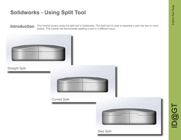
LINE SET PIPING DIAGRAMSThese are two options for running the lineset from the coil to the condensing unit.is installed with the condensing unit belowor leveled to the coil. Option 2 is for whenthe system is installed with thecondensing unit at a higherelevation than the coil.Option 1Option 2Page 22 1-800-343-9463MPS 031413
INSTALLING THE CONDENSING UNITRefrigerant Piping ProceduresWhen installing/routing the lines set, cap both ends of each tube to prevent material or debris from entering thetubing.Prior to connecting the piping, loosely connect the refrigerant gauges to the service ports of the suction and liquidline service valves. Purge the charging hoses with dry Nitrogen and tighten the hose connections. Remove the servicevalve caps and turn the valve stem clockwise (half of a complete turn) in order to unseat the valve and open theservice port. The valve comes in a back seated position from the factory. Keep the piping port sealed until ready toconnect to the vacuum pump.Cleanliness is of the utmost importance. All horizontal suction piping should be pitched toward the condensing unitInsulation Adhesive or equivalent. Wrap each seam using line set tape.Liquid Line Piping ProcedureIt is required to use a 1/4” OD Copper tube liquid line. When making connections keep the ends sealed until ready toDownstream, connect the moisture indicating sight glass in an easily visible location. Run the tubing to the EvaporatorEvaporator Unit (Fan Coil Unit) and set the temperature controller to call for cooling, this will activate the liquid lineSuction Piping ProcedureUnit (Fan Coil Unit) outlet connection. Install a Schrader Type Access valve at the outlet of the Evaporator Unit (Fanafter leak testing.After all piping ran and ready for the brazing process: Energize the Evaporator Unit (Fan Coil Unit) and set thetemperature controller to call for cooling. Open the liquid line service valve and bleed the nitrogen through boththe liquid and suction line. Loosen the suction gauge hose to relieve pressure during the brazing process. Braze theadd a small amount of 134a to both the high and low sides.Leak TestingUsing Dry Nitrogen pressurize the system to 200 PSI. Check to see if there is a noticeable pressure drop, if so locate andthere are no leaks, release the nitrogen pressure and leave the solenoid valve energized.Insulate the 3/8” suction line with the 10” piece of supplied cork tape.www.whisperkool.com Page 23
INSTALLING THE CONDENSING UNITEvacuationConnect evacuation type four valve gauge manifold to high and low pressure service valve ports on the condensingunit with the valve stems mid seated as when leak testing. Install service caps on valves and tighten them. Energizethe liquid line solenoid valve (make sure there is fresh oil in the vacuum pump). Connect a micron gauge directly toof reading that vacuum. Connect the micron gauge to the access valve installed in the suction line at the evaporator.Remove the Schrader valve depressors from the gauge hoses to reduce restriction and connect gauges to the suctionand liquid line service valve service ports on the condensing unit. Connect the pump to the 3/8” hose on the manifoldset, start the pump and run until the micron gauge reads 200 microns.When a 200 micron level evacuation is achieved, break the vacuum with R-134a and add enough refrigerant topressurize the system with a few psi of positive pressure.ChargingRemove the vacuum pump and the micron gauge. Install a spare low pressure gauge to the access valve at therefrigerant to the system through the high pressure side,Fill a wine bottle ¾ full with water between 60-75 degrees. Insert the bottle probe into the neck of the bottle as far aspossible. (It is important the bottle probe stopper is compressed by the neck of the bottle to ensure water will not leakout.). Verify that the bottle probe is properly installed and the set point on the controller is low enough to allow thesystem to run continuously for 30 minutes or more. Turn on power to the condensing unit and the compressor shoulddelay relay time to the lowest setting to avoid having to wait. Add refrigerant as a vapor through the low pressure sideof the system (suction service valve port).Observe the sight glass when the compressor starts. If bubbles are present, slowly add more refrigerant in vaporform to the low side. The suction pressure and
PLATINUM MINI-SPLIT SPECIFICATIONS Model Mini Evaporator Unit (Fan Coil Unit) Mini Condenser Cellar Size (cu. ft.) 500 Dimensions 20"w x 10.5"h x 11.25"d 11.5"w x 9.9"h x 16"d BTUh with 90 air entering the condenser coil. 1540 CFM 94 190 Refrigerant R-134a Condensing Unit HP 1/5 Voltage Rating (20 amp dedicated circuit required)