Transcription
Ductless Mini-Split Heat Pump Air ConditionerInstallation 78421-548-754IMPORTANT NOTE:Read this manual carefully before installingor operating your new air conditioningunit. Make sure to save this manual forfuture reference.
Table of ContentsInstallation Manual0 Safety Precautions. 41 Accessories.62 Installation Summary - Indoor Unit. 83 Unit Parts.104 Indoor Unit Installation. 111. Select installation location.112. Attach mounting plate to wall.123. Drill wall hole for connective piping.124. Prepare refrigerant piping.145. Connect drain hose.156. Connect signal cable.177. Wrap piping and cables.188. Mount indoor unit. 185 Outdoor Unit Installation. 201. Select installation location.202. Install drain joint. 213. Anchor outdoor unit. 224. Connect signal and power cables.23
6 Refrigerant Piping Connection. 25A. Note on Pipe Length. 25B. Connection Instructions –Refrigerant Piping. 251. Cut pipe. 252. Remove burrs. 263. Flare pipe ends. 264. Connect pipes. 27MCMC7 Air Evacuation. 291. Evacuation Instructions. 292. Note on Adding Refrigerant.308 Electrical and Gas Leak Checks. 319 Test Run. 3210 European Disposal Guidelines. 3411 Impedance Information. 35
Safety PrecautionsRead Safety Precautions Before InstallationIncorrect installation due to ignoring instructions can cause serious damage or injury.The seriousness of potential damage or injuries is classified as either a WARNING or CAUTION.This symbol indicates that ignoring instructions may cause death or seriousinjury.WARNINGThis symbol indicates that ignoring instructions may cause moderate injuryto your person, or damage to your unit or other property.CAUTIONThis symbol indicates that you must never perform the action indicated.WARNINGDo not modify the length of the power supply cord or use an extension cord to power the unit.Do not share the electrical outlet with other appliances. Improper or insufficient power supplycan cause fire or electrical shock.When connecting refrigerant piping, do not let substances or gases other than the specifiedrefrigerant enter the unit. The presence of other gases or substances will lower the unit’s capacity,and can cause abnormally high pressure in the refrigeration cycle. This can cause explosion andinjury.Do not allow children to play with the air conditioner. Children must be supervised around theunit at all times.1. Installation must be performed by an authorized dealer or specialist. Defective installation cancause water leakage, electrical shock, or fire.2. Installation must be performed according to the installation instructions. Improper installation cancause water leakage, electrical shock, or fire.(In North America,installation must be performed in accordance with the requirement of NEC andCEC by authorized personnel only.)3. Contact an authorized service technician for repair or maintenance of this unit.4. Only use the included accessories, parts, and specified parts for installation. Using non-standardparts can cause water leakage, electrical shock, fire, and can cause the unit to fail.5. Install the unit in a firm location that can support the unit’s weight. If the chosen location cannotsupport the unit’s weight, or the installation is not done properly, the unit may drop and causeserious injury and damage. Page 4
WARNING6. For all electrical work, follow all local and national wiring standards, regulations, and theInstallation Manual. You must use an independent circuit and single outlet to supply power. Donot connect other appliances to the same outlet. Insufficient electrical capacity or defects inelectrical work can cause electrical shock or fire.7. For all electrical work, use the specified cables. Connect cables tightly, and clamp them securely toprevent external forces from damaging the terminal. Improper electrical connections can overheatand cause fire, and may also cause shock.8. All wiring must be properly arranged to ensure that the control board cover can close properly. Ifthe control board cover is not closed properly, it can lead to corrosion and cause the connectionpoints on the terminal to heat up, catch fire, or cause electrical shock.9. In certain functional environments, such as kitchens, server rooms, etc., the use of specially designedair-conditioning units is highly recommended.10. If the supply cord is damaged, it must be replaced by the manufacturer, its service agent or similarlyqualified persons in order to avoid a hazard.11. This appliance can be used by children aged from 8 years and above and persons with reducedPhysical, sensory or mental capabilities or lack of experience and knowledge if they have been givensupervision or instruction concerning use of the appliance in a safe way and understand the hazardsinvolved. Children shall not play with the appliance. Cleaning and user maintenance shall not bemade by children without supervision.CAUTIONFor units that have an auxiliary electric heater, do not install the unit within 1 meter (3 feet) ofany combustible materials.Do not install the unit in a location that may be exposed to combustible gas leaks. If combustiblegas accumulates around the unit, it may cause fire.Do not operate your air conditioner in a wet room such as a bathroom or laundry room. Toomuch exposure to water can cause electrical components to short circuit.1. The product must be properly grounded at the time of installation, or electrical shock may occur.2. Install drainage piping according to the instructions in this manual. Improper drainage may causewater damage to your home and property.Note about Fluorinated Gasses1. This air-conditioning unit contains fluorinated gasses. For specific information on the type of gas2.3.4.5.and the amount, please refer to the relevant label on the unit itself.Installation, service, maintenance and repair of this unit must be performed by a certifiedtechnician.Product uninstallation and recycling must be performed by a certified technician.If the system has a leak-detection system installed, it must be checked for leaks at least every 12months.When the unit is checked for leaks, proper record-keeping of all checks is stronglyrecommended. Page 5
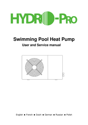
1AccessoriesThe air conditioning system comes with the following accessories. Use all of the installationparts and accessories to install the air conditioner. Improper installation may result in waterleakage, electrical shock and fire, or cause the equipment to fail.NameShapeQuantityMounting plate1Clip anchor5Mounting plate fixingscrew ST3.9 X 255Remote controller1Fixing screw for remotecontroller holder ST2.9 x 102OptionalPartsRemote controller holder1Dry battery AAA.LR03SealDrain joint Page 6 21(for cooling & heatingmodels only)
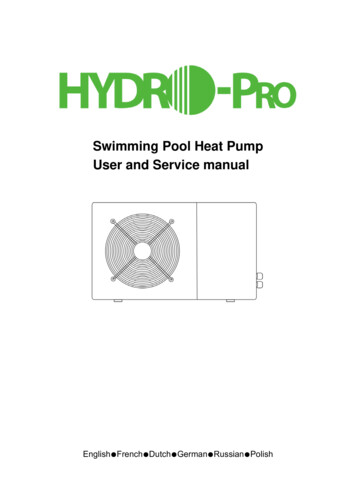
ShapeNameQuantitySPLIT-TYPE ROOM AIR CONDITIONEROwner’s ManualAurora SeriesAll Model Numbers1Owner’s manualCS78421-548-754IMPORTANT NOTE:Read this manual carefully before installingor operating your new air conditioningunit. Make sure to save this manual forfuture reference.SPLIT-TYPE ROOM AIR CONDITIONERInstallation ManualInstallation manualAurora SeriesAll Model Numbers1CS78421-548-754IMPORTANT NOTE:Read this manual carefully before installingor operating your new air conditioningunit. Make sure to save this manual forfuture reference.Remote controllerillustrationAIR CONDI TIONE RREMOTE CONTROL LER I LLUSTRATI ON1IMPORTANT NOTE:Read this manual carefully before installingor operating your new air conditioningunit. Make sure to save this manual forfuture reference.Connecting pipeassemblyLiquid sideΦ 6.35( 1/4 i n)Φ9.52( 3/8in)Φ9.52( 3/8in)Gas sideΦ12.7( 1/2in)Parts you must purc hase.Consult the dealer aboutthe pipe size.Φ16( 5/8in)Φ19( 3/4in) Page 7
InstallationOverviewInstallation Summary - Indoor Unit1215cm (5.9in)12cm(4.75in)212cm(4.75in)2.3m (90.55in)Select Installation Location(Page 11)3Determine Wall Hole Position(Page 12)4Attach Mounting Plate(Page 12) Page 8 Drill Wall Hole(Page 12)
6Connect Piping(Page 25)InstallationOverview57Connect Wiring(Page 17)Prepare Drain Hose(Page 14)8Wrap Piping and Cable(not applicable for some locations in the US )(Page 18)9STEP8Mount Indoor Unit(Page 18) Page 9
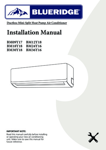
3Unit PartsInstallationOverviewNOTE: The installation must be performed in accordance with the requirement of local andnational standards. The installation may be slightly different in different areas.11Air-break switch322446536577889101111(1)(2)Fig. 2.11 Wall Mounting Plate52 Front Panel3 Power Cable (Some Units)4 Louver6Functional Filter (On Front ofMain Filter - Some Units)Drainage Pipe7 Signal Cable8 Refrigerant Piping9 Remote Controller10 Remote controller Holder(Some Units)11 Outdoor Unit Power Cable(Some Units)NOTE ON ILLUSTRATIONSIllustrations in this manual are for explanatory purposes. The actual shape of your indoorunit may be slightly different. The actual shape shall prevail. Page 10
Indoor Unit Installation4Indoor UnitInstallationInstallation Instructions – IndoorUnitPRIOR TO INSTALLATIONBefore installing the indoor unit, refer to thelabel on the product box to make sure that themodel number of the indoor unit matches themodel number of the outdoor unit.Step 1: Select installation locationBefore installing the indoor unit, you mustchoose an appropriate location. The followingare standards that will help you choose anappropriate location for the unit.Proper installation locations meet thefollowing standards: Good air circulation Convenient drainage Noise from the unit will not disturb otherpeople Firm and solid—the location will not vibrate Strong enough to support the weight of theunit A location at least one meter from all otherelectrical devices (e.g., TV, radio, computer)DO NOT install unit in the followinglocations:Near any source of heat, steam, orcombustible gasNear flammable items such as curtains orclothingNear any obstacle that might block aircirculationNear the doorwayIn a location subject to direct sunlightNOTE ABOUT WALL HOLE:If there is no fixed refrigerant piping:While choosing a location, be aware that youshould leave ample room for a wall hole (seeDrill wall hole for connective piping step)for the signal cable and refrigerant pipingthat connect the indoor and outdoor units.The default position for all piping is the rightside of the indoor unit (while facing the unit).However, the unit can accommodate piping toboth the left and right. Page 11
Refer to the following diagram to ensure proper distance from walls and ceiling:15cm (5.9in) or moreIndoor UnitInstallation12cm (4.75in)or more12cm (4.75in)or more2.3m (90.55in) or moreFig. 3.1Step 2: Attach mounting plate to wallThe mounting plate is the device on which youwill mount the indoor unit.1. Remove the screw that attaches the mountingplate to the back of the indoor unit.2. Place the mounting plate against the wallin a location that meets the standards inthe Select Installation Location step. (SeeMounting Plate Dimensions for detailedinformation on mounting plate sizes.)3. Drill holes for mounting screws in places that: have studs and can support the weight ofthe unit correspond to screw holes in the mountingplate4. Secure the mounting plate to the wall withthe screws provided.5. Make sure that mounting plate is flat againstthe wall.NOTE FOR CONCRETE OR BRICK WALLS:If the wall is made of brick, concrete, or similarmaterial, drill 5mm-diameter (0.2in-diameter)holes in the wall and insert the sleeve anchorsprovided. Then secure the mounting plate tothe wall by tightening the screws directly intothe clip anchors. Page 12 Step 3: Drill wall hole for connective pipingYou must drill a hole in the wall for refrigerantpiping, the drainage pipe, and the signal cablethat will connect the indoor and outdoor units.1. Determine the location of the wall hole basedon the position of the mounting plate. Referto Mounting Plate Dimensions on thenext page to help you determine the optimalposition. The wall hole should have a 65mm(2.5in) diameter at least, and at a slightlylower angle to facilitate drainage.2. Using a 65mm (2.5in) or 90mm(3.54in)(depending on models )core drill, drill ahole in the wall. Make sure that the holeis drilled at a slight downward angle, sothat the outdoor end of the hole is lowerthan the indoor end by about 5mm to 7mm(0.2-0.27in). This will ensure proper waterdrainage. (See Fig. 3.2)3. Place the protective wall cuff in the hole. Thisprotects the edges of the hole and will helpseal it when you finish the installation process.CAUTIONWhen drilling the wall hole, make sure toavoid wires, plumbing, and other sensitivecomponents.
IndoorWallOutdoor179mm (7.05in)136mm (5.35in)49mm (1.95in)Indoor unit outline49mm (1.95in)5-7mm(0.2-0.27in)290mm (11.4in)101mm (4in)37mm (1.45in)348.4mm (13.7in)722mm (28.45in)Right rear wallhole 65mm (2.5in)426mm (16.8in)43mm (1.7in)144mm (5.65in)57mm (2.25in)58mm (2.3in)517.4mm (20.37in)319mm (12.55in)43mm (1.7in)43mm (1.7in)Right rear wallhole 65mm (2.5in)802mm (31.6in)138mm (5.45in)40mm (1.55in)Indoor unit outline34mm (1.35in)965mm (38in)Right rear wallhole 65mm (2.5in)Model C553mm (21.77in)300mm (11.8in)219mm (8.6in)76mm(3in)53.5mm (2.1in)47mm (1.85in)53.5mm(2.1in)148.7mm(5.85in)Indoor unit outline47mm (1.85in)Left rear wall174.3mm (6.85in)hole 65mm (2.5in)1080mm (42.5in) 151mm (5.95in)Right rear wallhole 65mm (2.5in)Model D643.6mm (25.3in)257mm (10.1in)389mm (15.3in)172mm (6.8in)332mm (13.05in)362mm (14.25in)Correct orientation of Mounting PlateIndoor unit outlineLeft rear wallhole 65mm (2.5in)335mm (13.2in)MOUNTING PLATE DIMENSIONSDifferent models have different mounting plates.In order to ensure that you have ample room tomount the indoor unit, the diagrams to the rightshow different types of mounting plates alongwith the following dimensions: Width of mounting plate Height of mounting plate Width of indoor unit relative to plate Height of indoor unit relative to plate Recommended position of wall hole (bothto the left and right of mounting plate) Relative distances between screw holes297mm (11.7in)Fig. 3.2Fig.3.2128mm (5.05in)Left rear wallhole 65mm (2.5in)Indoor unit outline52mm (2.05in)1259mm (49.55in)52mm (2.05in)Right rear wallhole 65mm (2.5in)Model ENOTE: When the gas side connective pipe isΦ 16mm(5/8in) or more, the wall hole shouldbe 90mm(3.54in). Page 13 Indoor UnitInstallation232mm (9.15in)192mm (7.55in)
Step 4: Prepare refrigerant pipingThe refrigerant piping is inside an insulatingsleeve attached to the back of the unit. You mustprepare the piping before passing it through thehole in the wall. Refer to the Refrigerant PipingConnection section of this manual for detailedinstructions on pipe flaring and flare torquerequirements, technique, etc.Indoor UnitInstallation1. Based on the position of the wall hole relativeto the mounting plate, choose the side fromwhich the piping will exit the unit.2. If the wall hole is behind the unit, keep theknock-out panel in place. If the wall hole is tothe side of the indoor unit, remove the plasticknock-out panel from that side of the unit.(See Fig. 3.3 ). This will create a slot throughwhich your piping can exit the unit. Useneedle nose pliers if the plastic panel is toodifficult to remove by hand.3. Use scissors to cut down the length of theinsulating sleeve to reveal about 15cm (6in)of the refrigerant piping. This serves twopurposes: To facilitate the Refrigerant PipingConnection process To facilitate Gas Leak Checks and enableyou to check for dents4. If existing connective piping is alreadyembedded in the wall, proceed directly tothe Connect Drain Hose step. If there is noembedded piping, connect the indoor unit’srefrigerant piping to the connective pipingthat will join the indoor and outdoor units.Refer to the Refrigerant Piping Connectionsection of this manual for detailed instructions.5. Based on the position of the wall holerelative to the mounting plate, determine thenecessary angle of your piping.6. Grip the refrigerant piping at the base of thebend.7. Slowly, with even pressure, bend the pipingtowards the hole. Do not dent or damage thepiping during the process.NOTE ON PIPING ANGLERefrigerant piping can exit the indoor unit fromfour different angles: Left-hand side Left rear Right-hand side Right rearRefer to Fig. 3.4 for details.Knock-out PanelFig. 3.3Fig. 3.4CAUTIONBe extremely careful not to dent or damage the piping while bending them away from theunit. Any dents in the piping will affect the unit’s performance. Page 14
NOTE ON DRAIN HOSEPLACEMENTPLUG THE UNUSED DRAIN HOLETo prevent unwanted leaks you must plugthe unused drain hole with the rubber plugprovided.CORRECTMake sure there are nokinks or dent in drainhose to ensure properdrainage.Fig. 3.5NOT CORRECTKinks in the drain hosewill create water traps.Make sure to arrange the drain hoseaccording to Fig. 3.5.Fig. 3.6DO NOT kink the drain hose.DO NOT create a water trap.NOT CORRECTKinks in the drain hosewill create water traps.DO NOT put the end of drain hose inwater or a container that will collectwater.Fig. 3.7NOT CORRECTDo not place the endof the drain hose inwater or in containersthat collect water. Thiswill prevent properdrainage.Fig. 3.8 Page 15 Indoor UnitInstallationStep 5: Connect drain hoseBy default, the drain hose is attached to the lefthand side of unit (when you’re facing the backof the unit). However, it can also be attached tothe right-hand side.1. To ensure proper drainage, attach the drainhose on the same side that your refrigerantpiping exits the unit.2. Attach drain hose extension (purchasedseparately) to the end of drain hose.3. Wrap the connection point firmly with Teflontape to ensure a good seal and to preventleaks.4. For the portion of the drain hose that willremain indoors, wrap it with foam pipeinsulation to prevent condensation.5. Remove the air filter and pour a small amountof water into the drain pan to make sure thatwater flows from the unit smoothly.
BEFORE PERFORMING ELECTRICAL WORK, READ THESE REGULATIONS1. All wiring must comply with local and national electrical codes, and must be installed by alicensed electrician.2. All electrical connections must be made according to the Electrical Connection Diagramlocated on the panels of the indoor and outdoor units.3. If there is a serious safety issue with the power supply, stop work immediately. Explain yourreasoning to the client, and refuse to install the unit until the safety issue is properly resolved.Indoor UnitInstallation4. Power voltage should be within 90-110% of rated voltage. Insufficient power supply cancause malfunction, electrical shock, or fire.5. If connecting power to fixed wiring, install a surge protector and main power switch with acapacity of 1.5 times the maximum current of the unit.6. If connecting power to fixed wiring, a switch or circuit breaker that disconnects all poles andhas a contact separation of at least 1/8in (3mm) must be incorporated in the fixed wiring. Thequalified technician must use an approved circuit breaker or switch.7. Only connect the unit to an individual branch circuit outlet. Do not connect another applianceto that outlet.8. Make sure to properly ground the air conditioner.9. Every wire must be firmly connected. Loose wiring can cause the terminal to overheat,resulting in product malfunction and possible fire.10. Do not let wires touch or rest against refrigerant tubing, the compressor, or any moving partswithin the unit.11. If the unit has an auxiliary electric heater, it must be installed at least 1 meter (40in) awayfrom any combustible materials.WARNINGBEFORE PERFORMING ANY ELECTRICAL OR WIRING WORK, TURN OFF THE MAIN POWERTO THE SYSTEM. Page 16
Step 6: Connect signal cableThe signal cable enables communication betweenthe indoor and outdoor units. You must firstchoose the right cable size before preparing it forconnection.Cable Types Indoor Power Cable (if applicable):Minimum Cross-Sectional Area ofPower and Signal CablesNorth AmericaAppliance Amps (A)1013182530AWG18161412101. Prepare the cable for connection:a. Using wire strippers, strip the rubber jacketfrom both ends of signal cable to revealabout 40mm (1.57in) of the wires inside.b. Strip the insulation from the ends of thewires.c. Using wire crimper, crimp u-type lugs onthe ends of the wires.PAY ATTENTION TO LIVE WIREWhile crimping wires, make sure you clearlydistinguish the Live (“L”) Wire from other wires.2. Open front panel of the indoor unit.3. Using a screwdriver, open the wire box coveron the right side of the unit. This will revealthe terminal block.Other RegionsRated Current ofNominal Cross-SectionalArea (mm²)Appliance (A) 3 and 60.75 6 and 101 10 and 161.5 16 and 252.5 25 and 324 32 and 406CHOOSE THE RIGHT CABLE SIZEThe size of the power supply cable, signalcable, fuse, and switch needed is determinedby the maximum current of the unit. Themaximum current is indicated on the nameplatelocated on the side panel of the unit. Refer tothis nameplate to choose the right cable, fuse,or switch.Terminal blockWire coverScrewCable clampFig. 3.9The Wiring Diagram is locatedon the inside of the indoor unit’swire cover.WARNINGALL WIRING MUST PERFORMED STRICTLYIN ACCORDANCE WITH THE WIRINGDIAGRAM LOCATED ON THE INSIDE OF THEINDOOR UNIT ’S WIRE COVER.4. Unscrew the cable clamp below the terminalblock and place it to the side.5. Facing the back of the unit, remove the plasticpanel on the bottom left-hand side. Page 17 Indoor UnitInstallationH05VV-F or H05V2V2-F Outdoor Power Cable: H07RN-F Signal Cable: H07RN-FTAKE NOTE OF FUSE SPECIFICATIONSThe air conditioner’s circuit board (PCB) isdesigned with a fuse to provide overcurrentprotection. The specifications of the fuseare printed on the circuit board, such as:T3.15A/250VAC, T5A/250VAC, etc.
6. Feed the signal wire through this slot, fromthe back of the unit to the front.7. Facing the front of the unit, match the wirecolors with the labels on the terminal block,connect the u-lug and and firmly screw eachwire to its corresponding terminal.CAUTIONIndoor UnitInstallationDO NOT MIX UP LIVE AND NULL WIRESThis is dangerous, and can cause the airconditioning unit to malfunction.8. After checking to make sure every connectionis secure, use the cable clamp to fasten thesignal cable to the unit. Screw the cable clampdown tightly.9. Replace the wire cover on the front of theunit, and the plastic panel on the back.NOTE ABOUT WIRINGTHE WIRING CONNECTION PROCESS MAYDIFFER SLIGHTLY BETWEEN UNITS.Step 7: Wrap piping and cablesBefore passing the piping, drain hose, and thesignal cable through the wall hole, you mustbundle them together to save space, protectthem, and insulate them.1. Bundle the drain hose, refrigerant pipes, andsignal cable according to Fig. 3.10.Indoor UnitSpace behind unitRefrigerant pipingInsulation tapeSignal wireDrain hoseFig. 3.10DRAIN HOSE MUST BE ON BOTTOMMake sure that the drain hose is at the bottomof the bundle. Putting the drain hose at thetop of the bundle can cause the drain panto overflow, which can lead to fire or waterdamage. Page 18 DO NOT INTERTWINE SIGNAL CABLE WITHOTHER WIRESWhile bundling these items together, do notintertwine or cross the signal cable with anyother wiring.2. Using adhesive vinyl tape, attach the drainhose to the underside of the refrigerant pipes.3. Using insulation tape, wrap the signal wire,refrigerant pipes, and drain hose tightlytogether. Double-check that all items arebundled in accordance with Fig. 3.10.DO NOT WRAP ENDS OF PIPINGWhen wrapping the bundle, keep the endsof the piping unwrapped. You need to accessthem to test for leaks at the end of theinstallation process (refer to Electrical Checksand Leak Checks section of this manual).Step 8: Mount indoor unitIf you installed new connective piping to theoutdoor unit, do the following:1. If you have already passed the refrigerantpiping through the hole in the wall, proceedto Step 4.2. Otherwise, double-check that the ends of therefrigerant pipes are sealed to prevent dirt orforeign materials from entering the pipes.3. Slowly pass the wrapped bundle of refrigerantpipes, drain hose, and signal wire through thehole in the wall.4. Hook the top of the indoor unit on the upperhook of the mounting plate.5. Check that unit is hooked firmly on mountingby applying slight pressure to the left andright-hand sides of the unit. The unit shouldnot jiggle or shift.6. Using even pressure, push down on thebottom half of the unit. Keep pushing downuntil the unit snaps onto the hooks along thebottom of the mounting plate.7. Again, check that the unit is firmly mountedby applying slight pressure to the left and theright-hand sides of the unit.
If refrigerant piping is already embedded inthe wall, do the following:1. Hook the top of the indoor unit on the upperhook of the mounting plate.2. Use a bracket or wedge to prop up the unit,giving you enough room to connect therefrigerant piping, signal cable, and drainhose. Refer to Fig. 3.11 for an example.3. Connect drain hose and refrigerant piping4.5.6.Fig. 3.11UNIT IS ADJUSTABLEKeep in mind that the hooks on the mounting plate are smaller than the holes on the back of theunit. If you find that you don’t have ample room to connect embedded pipes to the indoor unit, theunit can be adjusted left or right by about 30-50mm (1.25-1.95in), depending on the model. (SeeFig. 3.12.)30-50mm(1.2-1.95in)30-50mm(1.2-1.95in)Move to left or rightFig. 3.12 Page 19 Indoor UnitInstallation7.(refer to Refrigerant Piping Connectionsection of this manual for instructions).Keep pipe connection point exposed toperform the leak test (refer to ElectricalChecks and Leak Checks section of thismanual).After the leak test, wrap the connection pointwith insulation tape.Remove the bracket or wedge that is proppingup the unit.Using even pressure, push down on thebottom half of the unit. Keep pushing downuntil the unit snaps onto the hooks along thebottom of the mounting plate.
5Outdoor Unit Installation60cm (24in) aboveOutdoor UnitInstallationInstallation Instructions – OutdoorUnitStep 1: Select installation locationBefore installing the outdoor unit, you mustchoose an appropriate location. The followingare standards that will help you choose anappropriate location for the unit.Proper installation locations meet thefollowing standards: Meets all spatial requirements shown inInstallation Space Requirements (Fig. 4.1) Good air circulation and ventilation Firm and solid—the location can support theunit and will not vibrate Noise from the unit will not disturb others Protected from prolonged periods of directsunlight or rain Page 20 30cmin) ll(12 wacm ck30 bamfro(12on le in)ftin)(79 tm0c ron20 in f60cm(2on r 4in)ightFig. 4.1DO NOT install unit in the following locations:Near an obstacle that will block air inletsand outletsNear a public street, crowded areas, orwhere noise from the unit will disturb othersNear animals or plants that will be harmedby hot air dischargeNear any source of combustible gasIn a location that is exposed to largeamounts of dustIn a location exposed to a excessive amountsof salty air
SPECIAL CONSIDERATIONS FOR EXTREMEWEATHERIf the unit is exposed to heavy wind:Install unit so that air outlet fan is at a 90 angle to the direction of the wind. If needed,build a barrier in front of the unit to protect itfrom extremely heavy winds.See Fig. 4.2 and Fig. 4.3 below.Strong windStrong windWind BaffleBase pan hole ofoutdoor unitStrong windFig. 4.3SealSealIf the unit is frequently exposed to heavyrain or snow:Build a shelter above the unit to protectit from the rain or snow. Be careful not toobstruct air flow around the unit.If the unit is frequently exposed to salty air(seaside):Use outdoor unit that is specially designed toresist corrosion.Step 2: Install drain jointHeat pump units require a drain joint. Beforebolting the outdoor unit in place, you must installthe drain joint at the bottom of the unit. Notethat there are two different types of drain jointsdepending on the type of outdoor unit.Drain joint(A)(B)Fig. 4.4IN COLD CLIMATESIn cold climates, make sure that the drain hoseis as vertical as possible to ensure swift waterdrainage. If water drains too slowly, it canfreeze in the hose and flood the unit. Page 21 Outdoor UnitInstallationFig. 4.2If the drain joint comes with a rubber seal(see Fig. 4.4 - A ), do the following:1. Fit the rubber seal on the end of the drain jointthat will connect to the outdoor unit.2. Insert the drain joint into the hole in the basepan of the unit.3. Rotate the drain joint 90 until it clicks in placefacing the front of the unit.4. Connect a drain hose extension (not included)to the drain joint to redirect water from theunit during heating mode.If the drain joint doesn’t come with a rubberseal (see Fig. 4.4 - B ), do the following:1. Insert the drain joint into the hole in the basepan of the unit. The drain joint will click inplace.2. Connect a drain hose extension (not included)to the drain joint to redirect water from theunit during heating mode.
Step 3: Anchor outdoor unitThe outdoor unit can be anchoredto the ground or to a wall-mountedbracket.WAU
SPLIT-TYPE ROOM AIR CONDITIONER CS78421-548-754 IMPORTANT NOTE: Read this manual carefully before installing or operating your new air conditioning unit. Make sure to save this manual for future reference. Owner's Manual Aurora Series All Model Numbers SPLIT-TYPE ROOM AIR CONDITIONER CS78421-548-754 IMPORTANT NOTE: