Transcription
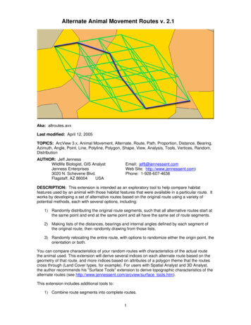
Alternate Animal Movement Routes v. 2.1Aka: altroutes.avxLast modified: April 12, 2005TOPICS: ArcView 3.x, Animal Movement, Alternate, Route, Path, Proportion, Distance, Bearing,Azimuth, Angle, Point, Line, Polyline, Polygon, Shape, View, Analysis, Tools, Vertices, Random,DistributionAUTHOR: Jeff JennessWildlife Biologist, GIS AnalystJenness Enterprises3020 N. Schevene Blvd.Flagstaff, AZ 86004USAEmail: jeffj@jennessent.comWeb Site: http://www.jennessent.com)Phone: 1-928-607-4638DESCRIPTION: This extension is intended as an exploratory tool to help compare habitatfeatures used by an animal with those habitat features that were available in a particular route. Itworks by developing a set of alternative routes based on the original route using a variety ofpotential methods, each with several options, including:1) Randomly distributing the original route segments, such that all alternative routes start atthe same point and end at the same point and all have the same set of route segments.2) Making lists of the distances, bearings and internal angles defined by each segment ofthe original route, then randomly drawing from those lists.3) Randomly relocating the entire route, with options to randomize either the origin point, theorientation or both.You can compare characteristics of your random routes with characteristics of the actual routethe animal used. This extension will derive several indices on each alternate route based on thegeometry of that route, and more indices based on attributes of a polygon theme that the routescross through (Land Cover types, for example). For users with Spatial Analyst and 3D Analyst,the author recommends his "Surface Tools" extension to derive topographic characteristics of thealternate routes (see http://www.jennessent.com/arcview/surface tools.htm).This extension includes additional tools to:1) Combine route segments into complete routes.1
2) Analyze habitat characteristics of routes by intersecting them with a habitat polygontheme and calculating the distances and proportions of each route that traverse eachunique habitat type.3) Analyze habitat characteristics of the buffered areas around the routes, again byintersecting them with habitat polygons and calculating the areas and proportions of eachroute buffer that overlays each unique habitat type.4) Add a field containing record numbers to a table.OUTPUT: This extension will generate polyline themes of alternate routes based on tables, pointthemes and polyline route themes. The alternate route themes include several indices describinggeometric aspects of the route and how much they deviate from the original route.The tools that analyze habitat characteristics will identify all unique polygon attributes inintersecting polygons, and then generate the length and the proportion of the route that layswithin each habitat type. In these cases you also have the option to save your clipped polylinesor polygons in a separate shapefile.REQUIRES: This extension requires that the file "avdlog.dll" be present in the ArcView/BIN32directory (or AVBIN/avdlog.dll) and that the Dialog Designer extension be located in yourArcView/ext32 directory, which they usually are if you're running AV 3.1 or better. The DialogDesigner doesn't have to be loaded; it just has to be available. If you are running AV 3.0a, youcan download the appropriate files for free from ESRI at:http://support.esri.com/index.cfm?fa downloads.patchesServicePacks.viewPatch&PID 25&MetaID 483REVISIONS: Version 2 adds methods to generate random routes based on segment lengthsand bearings independently, and to randomly relocate and rotate the entire route. Version 2 alsoincludes several stand-alone tools to intersect routes with polygons, combine route segments andto add record number fields to datasets.Version 2.1 (April 12, 2005) adds the option to randomize routes by randomly selecting from theoriginal set of internal angles in the original route. This version also fixes bugs relating to sortingby date, attempting to randomize segments in a polyline with 1 segment, and intersectingpolylines or polygons with background polygon themes or randomizing routes while not copyingany of the original fields to the new theme.Recommended Citation Format: For those who wish to cite this extension, the authorrecommends something similar to:Jenness, J. 2005. Alternate animal movement routes (altroutes.avx) extension for ArcView 3.x, v.2.1. Jenness Enterprises. Available at: http://www.jennessent.com/arcview/alternate routes.htm.Please let me know if you cite this extension in a publication (jeffj@jennessent.com). I will updatethe citation list to include any publications that I am told about.2
Table of ContentsGENERAL INSTRUCTIONS: . 4RANDOMIZE ROUTE SEGMENTS:. 5RANDOMIZE SEGMENT LENGTHS AND BEARINGS:. 12RANDOMIZE ROUTE LOCATION AND ORIENTATION:. 18ADDITIONAL TOOLS:. 21Intersect Route Polylines with Habitat Polygons: . 21Intersect Route Polygons with Habitat Polygons: . 23Combine Route Segments into Route: . 25Add Record Numbers to Table: . 25ADDITIONAL TOPICS . 26Average Vertex Angles . 26Vertex Distances:. 28Polygon Area Distances:. 293
General Instructions:1) Begin by placing the "altroutes.avx" file into the ArcView extensions directory(././Av gis30/Arcview/ext32/).2) After starting ArcView, load the extension by clicking on File -- Extensions , scrollingdown through the list of available extensions, and then clicking on the checkbox next to theextension called "Alternate Animal Movement Routes."3) Make sure your input themes and/or input tables are present in your project. This extensionlets you select your input data from a list of themes/tables that are currently available in yourproject. It is not written to let you search the hard drive for your input data.4) When loaded, the extension will add a new menu to your View menu bar named “AlternateRoutes”:5) The extension will also add a menu item to your Table Edit menu labeled “Create RecordNumber Field”:4
Randomize Route Segments:This option will break each input route into a set of vertex-to-vertex segments, then randomlyrearrange those segments into a new route. Each segment will be moved so that it starts at theend of the previous segment. The end result will be a new alternate route that starts and ends atthe same place the previous route did, but which may go through entirely different areas and bemuch straighter or more crooked than the original route. There are options regarding how manyroutes to generate and whether a boundary polygon should be included.Instructions:Identify Input Data Type: This tool can generate random routes based on polyline themes, pointthemes or tables. If the input dataset is a polyline theme, the tool will treat each line in the themeas a separate route. In this case, you have the option to include any of the original route attributefields in the output shapefile of random routes. If the input dataset is a point theme or table, thenthe tool will assemble the routes from the points or the X- and Y-Coordinates. NOTE: If yourdataset is a polyline theme of portions or segments of a route, you will need to combine thoseportions into complete route features before using this tool. See Combine Route Segments IntoRoute on page 25.Start by clicking the “Randomize Route Segments ” menu item in the “Alternate Routes” menu.You will first be prompted to identify your input data type:Each data type option will open a different dialog, prompting you for the necessary information toidentify the route features in the data. The buttons with the question marks give details on thetypes and requirements of each data option:5
1) INPUT LINE THEME: All lines in the theme represent complete separate routes you want toanalyze. The Feature Attribute Table should include a field containing 'Line ID' values, andthese ID values can be used to see which random routes correspond with which originalroute. Random routes will be generated for each of the input lines, and you have the optionto specify which fields from the original line will be added to the random routes.2) INPUT POINT THEME: Each point in the theme represents a vertex or point along the route.The Feature Attribute Table should include fields containing 'Line ID' and 'Sort Order' values(see the note on Sort Order below). The point theme can contain points for multiple routes.These points will be divided into separate routes according to their Line ID values, and sortedaccording to their Sort Order values. The sorted lists of points will then be assembled intocomplete routes, and these routes will form the basis for the random routes.All random routes will include the respective Line ID values in the attribute table so you willknow which original route is associated with each random route.3) INPUT TABLE: Each record in the table reflects a single point (or vertex) in the route. The tableshould include fields containing 'Line ID', 'Sort Order', 'X-Coordinate' and 'Y-Coordinatevalues (see the note on Sort Order below). The table can contain records for multiple routes.Each record will be converted to a point based on the X- and Y-coordinates, and these pointswill be divided into separate routes according to their Line ID values and sorted according totheir Sort Order values. The sorted lists of points will then be assembled into completeroutes, and these routes will form the basis for the random routes.All random routes will include the respective Line ID values in the attribute table so you willknow which original route is associated with each random route.6
A NOTE REGARDING SORT ORDER: In cases where this extension requires that you specify thesorting order of your points or records, it is important to know if the values in your "SORTORDER" field are in "String" format or "Numeric" format. The extension will sort the featuresbased on the "SORT ORDER" field regardless of whether they are Strings or Numbers, but youshould be aware that numbers in string format have a different sort order than numbers innumeric format. Strings are sorted alphabetically while numbers are sorted numerically. Thenumbers 1 through 21 are sorted in the following ways:A. Numeric Format: 1, 2, 3, 4, 5, 6, 7, 8, 9, 10, 11, 12, 13, 14, 15, 16, 17, 18, 19, 20, 21B. String Format: 1, 10, 11, 12, 13, 14, 15, 16, 17, 18, 19, 2, 20, 21, 3, 4, 5, 6, 7, 8, 9If you want to sort the points in the order they appear in the attribute table, the best option is toadd a field to your attribute table containing record numbers (see Adding Record Numbers toTables on page 25), or simply choose the option “– Use Record Order –“ in the list.It is important that you don’t have duplicate sort values for any particular route, because the toolwill probably sort the records incorrectly and might even crash. The extension will check forduplicate Sort values and alert you if it finds any:Specify Randomization Parameters: After you have identified your data type, input theme andappropriate attribute fields, the tool will assemble the routes in memory and calculate how manypotential alternate routes exist based on the number of possible permutations of segments foreach route. You will then be prompted to identify the number of random alternative routes togenerate and a few other parameters:7
Number of Random Routes: First specify whether you would like to generate all possible randomroutes or if you would like to set a maximum number per input route. This extension will let youknow the total number of random routes possible for each input route and give you the option togenerate all possible alternatives.Polyline Output Options: This option will create a polyline theme of random alternate routes withseveral potential fields describing each route. These fields include identifiers for each route, fourmeasures of how much that alternate route deviates from the original route, and potentially dataregarding how much each route crosses over some particular attribute of interest (see thediscussion on intersecting routes with polygons on page 21). You have the option to select whichof the following fields will be included: Original Line ID: This is the ID value of the Original Route. If you conduct an analysis onmultiple routes simultaneously, this field will identify which original route that particularalternative route is associated with. Alternate Line ID: This field assigns a unique numerical value to each alternative line. Line Length: The length of that alternative route in map units. All alternative routesassociated with a particular original route will have the same length. Tot. Vertex Dist.: This extension can calculate the distance from the original line to eachvertex on that particular alternative route. This field contains the sum of all the distances. Avg. Vertex Dist.: This field takes the total vertex distance and divides it by the number ofvertices. This field may be more appropriate for comparing routes with different numbers ofroute segments than the total vertex distance. Please see the discussion on VertexDistances on page 28 for an illustration of this measure.8
Polygon Area Dist.: This is a measure of the land area bounded by the original route andthe alternate route. Please see the discussion on Polygon Area Distances on page 29 foran illustration of this measure. Straightness Index: This is a measure of how straight the route is, calculated by dividing thetotal route length by the straight-line distance from the route beginning to the route end.These values will range from 0 to 1, where 1 means the route is perfectly straight and 0means the route is infinitely crooked. All alternative routes derived from a single originalroute will have the same straightness index because they all are the exact same length andthey all have the same beginning and ending points. Average Internal Angle: This is a measure of how much the line bends. Alternative routesmay bend more or less than the original route. This measure reflects the average anglebound by each connected pair of line segments, and takes the average of all the bends inthe line. Please see the discussion on Average Vertex Angles on page 26 for an illustrationof this measure. Average Deviation Angle: This is another measure of how much the line bends, closelyrelated to the average internal angle. This measure reflects how much the bearing of asegment deviates from the bearing of the segment before it, and takes the average of all thedeviation angles in the line. Please see the discussion on Average Vertex Angles on page26 for an illustration of this measure. original: A True/False field reflecting whether that particular route is the original route or not. Fields containing Length and Proportion of Polylines that cross over Polygons: This optionwill let you select a particular attribute field from a polygon theme and create separate fieldsfor the length and proportion of the polylines that have each attribute. If any of thealternative routes go outside of the polygons completely, you will also get a field for thelength and proportion of the route that falls outside of the polygons (see the discussion onintersecting routes with polygons on page 21). IMPORTANT: These fields will only beadded if you choose to intersect your routes with a background polygon theme (see“Intersect with Polygon Theme:” below)Point Output Options: You have the option to create a separate Point shapefile containing thevertices of each of the alternative lines. The Feature Attribute Table for these points can containfields identifying each point by original route, by alternative route, or by a unique identifier foreach point. The table can also include fields containing the X- and Y-Coordinates for each pointand the distance from that point back to the original line. You also have the option to include afield containing the polygon attribute that the point overlays (see discussion below). You have theoption to choose from the following fields: Original Line ID: This is the ID value of the Original Route. Multiple alternative routes may bederived from this same original route, and this field will allow you to identify which originalroute produced this particular alternative route. Alternate Line ID: This is the unique numeric value of each alternative route. This will tell youwhich alternative route contains this particular vertex point. Point ID: This assigns a unique numerical value to each individual vertex. X-Coordinate: The X-coordinate of the vertex, in map units. Y-Coordinate: The Y-coordinate of the vertex, in map units. Distance from Line: The Distance of the vertex from the original line, in map units. Pleasesee the discussion on Vertex Distances on page 28 for an illustration of this measure. original: A True/False field reflecting whether that vertex comes from the original route ornot.9
Polygon Attribute: This is the attribute value of the background or habitat polygon the vertexsits in, based on the Polygon theme and the Attribute Field that you select. This field willonly be added if you choose to intersect your routes with a background polygon theme (see“Intersect with Polygon Theme:” below).Constrain Routes Within Polygon: If you have a theme containing a polygon or polyline boundaryfeature that you know your random routes should not cross, you can check the “Constrain RoutesWithin Boundary Area” option. IMPORTANT: This option will be disabled if you elect to generateall possible alternative routes for your input routes (see above). If you select this option, you willbe asked to identify your boundary theme and ID field:Intersect with Polygon Theme:If you have any polygon themes available in your view, you will have to opportunity to calculatethe length and proportion of each route that goes through each unique polygon type. Please referto the discussion on intersecting routes with polygons on page 21 for details on this operation.You will only see the following dialog if you have polygon themes in your view:10
If you have elected to generate a point shapefile of your random route vertices, then this functionwill also add a polygon attribute field to your point shapefile. The final point theme will includepolygon attribute values for all points, reflecting the attribute value of the polygon intersectingeach point.Saving Intersected Polylines: If you have elected to create a polyline shapefile of alternativeroutes, and you have designated a polygon theme with attribute values, then you have the optionto create a new polyline shapefile containing all the individual polyline segments that have beenclipped to the polygons, along with the polygon attribute values. The extension must clip thealternative routes to the polygon coverage in order to calculate the lengths and proportionsdescribed in the "POLYLINE OUTPUT" above, and this just gives you the option to save thoseclipped polylines to a separate shapefile. If you choose to save these line segments, your LineSegment Feature Attribute Table will contain the following fields: Length: The length of the line segment, in map units Proportion: The percentage of the total line that the line segment comprises. Original Line ID: This is the ID value of the Original Route. Multiple alternative routes may bederived from this same original route, and this field allows you to identify which original routeproduced this particular alternative route. Alternate Line ID: This is the ID value of the particular alternative route that this line segmentcomes from. Line Segment ID: This assigns a unique numeric value to each line segment. Polygon Attribute: This is the attribute value of the polygon the line segment sits in. Thisattribute value is based on the polygon theme and the attribute field that you selected. original: A True/False field reflecting whether this line segment comes from the original routeor not.Finally, you will be asked where you would like to save any of your output shapefiles. Thesedialogs should be familiar to most ArcView users, and you will be asked for a separate name andlocation for each output shapefile you specified.11
Randomize Segment Lengths and Bearings:This option will examine each vertex-to-vertex segment along the original route and buildseparate lists of the distances and bearings traveled in that segment. The random routes aregenerated by starting at the original route origin and then randomly selecting from the lists ofdistances and bearings. There are several options regarding selecting with replacement,selecting from only one of the lists or applying a boundary feature.Instructions:Identify Input Data Type: This tool can generate random routes based on polyline themes, pointthemes or tables. If the input dataset is a polyline theme, the tool will treat each line in the themeas a separate route. In this case, you have the option to include any of the original route attributefields in the output shapefile of random routes. If the input dataset is a point theme or table, thenthe tool will assemble the routes from the points or the X- and Y-Coordinates. NOTE: If yourdataset is a polyline theme of portions or segments of a route, you will need to combine thoseportions into complete route features before using this tool. See Combine Route Segments IntoRoute on page 25.Start by clicking the “Randomize Segment Lengths/Bearings ” menu item in the “AlternateRoutes” menu. You will first be prompted to identify your input data type:12
Each data type option will open a different dialog, prompting you for the necessary information toidentify the route features in the data. The buttons with the question marks give details on thetypes and requirements of each data option:4) INPUT LINE THEME: All lines in the theme represent complete separate routes you want toanalyze. The Feature Attribute Table should include a field containing 'Line ID' values, andthese ID values can be used to see which random routes correspond with which originalroute. Random routes will be generated for each of the input lines, and you have the optionto specify which fields from the original line will be added to the random routes.5) INPUT POINT THEME: Each point in the theme represents a vertex or point along the route.The Feature Attribute Table should include fields containing 'Line ID' and 'Sort Order' values(see the note on Sort Order below). The point theme can contain points for multiple routes.These points will be divided into separate routes according to their Line ID values, and sortedaccording to their Sort Order values. The sorted lists of points will then be assembled intocomplete routes, and these routes will form the basis for the random routes.All random routes will include the respective Line ID values in the attribute table so you willknow which original route is associated with each random route.6) INPUT TABLE: Each record in the table reflects a single point (or vertex) in the route. The tableshould include fields containing 'Line ID', 'Sort Order', 'X-Coordinate' and 'Y-Coordinatevalues (see the note on Sort Order below). The table can contain records for multiple routes.Each record will be converted to a point based on the X- and Y-coordinates, and these pointswill be divided into separate routes according to their Line ID values and sorted according totheir Sort Order values. The sorted lists of points will then be assembled into completeroutes, and these routes will form the basis for the random routes.All random routes will include the respective Line ID values in the attribute table so you willknow which original route is associated with each random route.13
A NOTE REGARDING SORT ORDER: In cases where this extension requires that you specify thesorting order of your points or records, it is important to know if the values in your "SORTORDER" field are in "String" format or "Numeric" format. The extension will sort the featuresbased on the "SORT ORDER" field regardless of whether they are Strings or Numbers, but youshould be aware that numbers in string format have a different sort order than numbers innumeric format. Strings are sorted alphabetically while numbers are sorted numerically. Thenumbers 1 through 21 are sorted in the following ways:C. Numeric Format: 1, 2, 3, 4, 5, 6, 7, 8, 9, 10, 11, 12, 13, 14, 15, 16, 17, 18, 19, 20, 21D. String Format: 1, 10, 11, 12, 13, 14, 15, 16, 17, 18, 19, 2, 20, 21, 3, 4, 5, 6, 7, 8, 9If you want to sort the points in the order they appear in the attribute table, the best option is toadd a field to your attribute table containing record numbers (see Adding Record Numbers toTables on page 25), or simply choose the option “– Use Record Order –“ in the list.It is important that you don’t have duplicate sort values for any particular route, because the toolwill probably sort the records incorrectly and might even crash. The extension will check forduplicate Sort values and alert you if it finds any:Specify Randomization Parameters: After you have identified your data type, input theme andappropriate attribute fields, the tool will ask you how many random routes to generate and whataspect of the original routes you wish to randomize:14
Random routes will be generated with the same number of segments as the original route and willall begin at the starting point of the original route. Optionally each segment can have the length,bearing, or internal angle between each pair of consecutive segments randomly drawn from thelist of existing lengths, bearings and internal angles for that route, or it can keep the originallength/bearing/internal angle of the original segment. If selecting randomly, you have the optionto select with replacement, in which case the same length/bearing/internal angle might beselected multiple times, or without replacement, in which case all original bearings, lengths orinternal angles will be included in the random routes.If you choose to randomly select from the list of internal angles of the original route, then the firstsegment on each random route will have the same bearing as the first segment on the originalroute. The internal angle between that segment and the next segment, and then for eachconsecutive pair of segments thereafter, will be selected at random from the list of internalangles.NOTE: Choosing “Original Segment Length” or “Original Segment Bearing” means that anyparticular segment in the new route will have the same length or bearing as it’s respectivesegment in the original route. The nth segment in the random routes will have the same distanceor bearing as the nth segment in the original route. If you set your options to both “OriginalSegment Length” and “Original Segment Bearing”, then your “random” routes will all be identicalto your original route.'Constrain Routes Within Boundary Area' means that the route will be prevented from goingoutside a particular polygon or across a polyline boundary. If you choose this option, you will beprompted to identify the polygon/polyline theme containing your boundary feature.15
Output Fields: The attribute table of your new shapefile of random routes will automaticallycontain the following fields: Unique ID: Just a unique ID value for each polyline in the shapefile. Boundary: The boundary ID value of any boundary polygon or polyline you may havespecified. If you did not choose to constrain routes within some kind of boundary region,the [Boundary] field will contain the string “None Specified”. Alt Length: The length of the polyline. Avg. Internal Angle: A measure of how much the line bends. Alternative routes may bendmore or less than the original route. This measure reflects the average angle bound byeach connected pair of line segments, and takes the average of all the bends in the line.Please see the discussion on Average Vertex Angles on page 26 for an illustration of thismeasure. Straightness: A measure of how straight the route is, calculated by dividing the totalroute length by the straight-line distance from the route beginning to the route end.These values will range from 0 to 1, where 1 means the route is perfectly straight and 0means the route is infinitely crooked. Avg. Deviation Angle: Another measure of how much the line bends, closely related tothe average internal angle. This measure reflects how much the bearing of a segmentdeviates from the bearing of the segment before it, and takes the average of all thedeviation angles in the line. Please see the discussion on Average Vertex Angles onpage 26 for an illustration of this measure. Possibly other fields: If your input theme was a Polyline theme, then you had the optionto select which fields to add to your new theme of random polylines (see above). Allfields selected in the “Select Line (or Polyline) Theme:” dialog will be added.In
OUTPUT: This extension will generate polyline themes of alternate routes based on tables, point themes and polyline route themes. The alternate route themes include several indices describing geometric aspects of the route and how much they deviate from the original route.