Transcription
GM TRUCK 07-13 BACKUP CAMERA INSTALLATIONThank you for your purchase! These instructions are intended for the do-it-yourselfer who decides to install thecamera without professional assistance. Keep in mind you will be installing a device that uses electrical powerfrom your computer controlled truck. If you are not confident in your ability to attach this device without fryingyour electrical system, new camera, or yourself please seek PROFESSIONAL INSTALLATION!BEFORE YOU BEGINCables: The camera harness is 4 feet long and will get you through the bottom of your tailgate andthrough the back of the bed. The chassis harness is 25’ long and is designed so that all electricalconnections can be made inside the cab as per the wiring instructions contained in this document. Thecamera connector should be tied up in an accessible location by the spare tire area so it can be accessedfor tailgate removal.If you are using the factory NAV screen as your display: You must have the dealer re-flash your NAVsystem for a backup camera. Any GM dealer can do it and it should cost around 100 or less. Just askthem to apply part #2583-6479 to the navigation unit. In addition, you may need a video interface thatallows you to connect the camera to the factory wiring harness at the back of the radio. We stock theGMX-550 NAV interface and the VSS pigtail adapter so check out our online catalog if you need aninterface for your navigation. You may also be able to connect directly to the navigation video input butit would require you to splice your RCA cable to the factory harness– see Appendix A.If you are using an aftermarket navigation display you should already have the proper video input andreverse trigger wire required for this installation.REQUIRED TOOLS-Standard wire stripper/crimper- 13mm socket wrench-Black tape or shrink tube-Razor knife or poking tool-1/4” and 1” drill bit or step bit (if holes are not pre-drilled at the factory)-Drill-RTV or butyl sealantSection 1: Setting up for the installation1
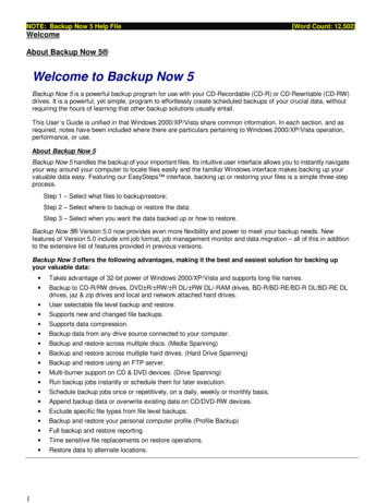
Unpack the contents of the package and gather the required tools listed above so you can be sure youhave everything you need before you begin. In the package you should have the bezel with camera,chassis harness, and a ziplock bag containing 2 snap busings, 2 red tap splices, 1 U-terminal, lock plug,and a handful of zip ties.1. Remove any plastic interior components to allow access to the necessary wires of your Lockpickor video interface device. This may include the side panel of the center console if applicable.You will need to remove your factory navigation unit if you plan to connect this camera directlyto the VSS harness or if you are installing a lockpick as part of this kit.2. Remove your old tailgate bezel - Use the 13mm socket wrench to remove the bottom bolt of thetailgate latch. Pull the tailgate handle up out of the way with one hand and firmly grab theplastic bezel with the other and give it a good tug. Be careful because it has a tendency to busta knuckle on the way out.3. Every truck we’ve ever seen has drain holes in the bottom of the tailgate and most newer trucks(usually 09‐up) have a hole in the back of the bed as well. If you already have holes in thetailgate and back of the bed, you do not have to remove the tailgate to run the camera cable,and can skip to Section 3. If you do not have the existing hole in the bed, remove the tailgatefrom the truck as per the factory manual. We will be drilling a hole in the bottom of the tailgate(OPTIONAL IF YOU USE THE DRAIN HOLE METHOD) and the rear of the bed for wire passage.Section 2: Drill the access holes (if not already there)1. Using a ¼” drill bit, drill a hole in the center of thepickup box end as shown in IMAGE 1. It is important tocenter it so that the hole can be expanded to 1”without going through the floor of the bed, but alsohigh enough so you can’t see the wires when thetailgate is closed. Once you get the ¼” hole drilled, youIMAGE 1can use your 1” bit to make it large enough to installone of the included plastic snap bushing.2. Making sure that the holes will line up, do the same to the bottom of your tailgate.3. Install the plastic snap bushings. These bushings provide an inside diameter large enough forthe loomed camera harness to slide through easily. Tip: install a slight amount of RTV to theexposed metal on both holes before installing the grommets to avoid rusting and help securethe grommets.Section 3: Connect the power to the camera1. Using a “fish” tool, drop the camera cable out the center tailgate drain hole (or freshly drilledhole) and through the existing (or freshly drilled hole) in the bed. The split loom will protect thecamera cable from sharp metal or other obstructions. You should leave enough slack so thecable can pull itself through the snap bushings easily when opening and closing the tailgate.Secure the connector in an easily accessible location so you can access it if you want to removethe tailgate.2
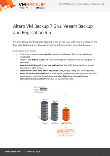
2. Connect the chassis harness to the camera harness plug. BE CAREFUL AS IT IS KEYED AND CANONLY GO TOGETHER ONE WAY! DO NOT FORCE IT TOGETHER!3. Run the chassis harness to the drivers floorboard area securing it with the included zip ties alongthe frame rail and away from any moving parts. Be careful that the cable didn’t comedisconnected from the camera while you were pulling it through the chassis.4. Almost every truck has a large grommet through the driver’s floor near the front left corner ofthe driver’s seat for the parking brake cable. We recommend using this grommet to route yourcamera cables through. If for some reason you don’t have this cable, you will have to findanother suitable location. Be careful not to damage any other vehicle wires if you are goingthrough an existing wiring harness!5. For those who have the cable accessmentioned above, remove the driver’s side sillplate and peel the carpet back far enough tosee the top of the grommet (see IMAGE 2).Being careful not to slice the cable, use yourrazor knife or poking tool to make a new holesomewhere in the grommet and expand itlarge enough for the head of your RCA cableto penetrate. BE CAREFUL NOT TO DAMAGETHE HEAD OF YOUR RCA CABLE WHENPUSHING IT THROUGH THE GROMMET. InIMAGE 2image 2 you can see that the camera wires are now sharing the grommet with an existing cable.This grommet will have to be resealed using your RTV or butyl tape but wait until the cables arein place (next step) to ensure you have the proper amount of slack at both ends.6. Push the cable(s) through the grommet location in the floor mentioned in the previous step, androute the RCA cable under the carpet toward the video interface unit or navigation receiver.Route the power/ground wires to the Left I/P Junction Block (it’s under the large square blackplastic cover to the left of the foot brake).7. As a final check make sure that the cable is now secure from all moving parts under the vehicle,through the holes created in the box and tailgate. Coil up any excess cable behind the dash orconsole and secure it with a zip tie. Once secure, use the RTV or butyl tape to seal the grommetthat you poked a hole in previously or you will end up with we carpet! Try to seal it from the topand bottom just to be sure. Now you can put your carpet and sill plates back together.Section 4: Connect your navigation or other monitor to the camera1. If you are using an aftermarket receiver or mirror monitor, plug the RCA video cable into theinput on your receiver or mirror harness. Secure the excess cable so it will not interfere withanything under the dash.2. (Lockpick users skip to step 5) Connect the red power wire to the reverse power source in theLeft I/P Junction Block (diagram in appendix) port X10, pin 8 – should be a dark blue wire. Thiswill provide power to the camera only when in reverse.3. Connect the black ground wire to Port X14, pin 1 or any clean metal surface.3
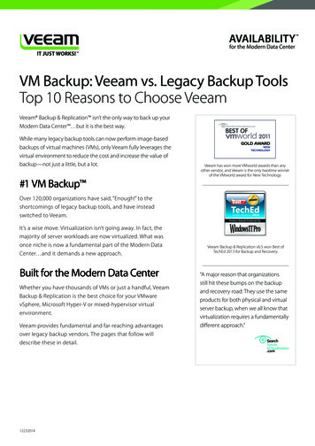
4. If you are connecting to your factory GM navigation and not using a Lockpick see the VSSharness pin locations in the appendix. Remove your navigation unit and unplug the brownconnector (VSS) to gain access to the required wires. If you purchased a CS-GMVSS navigationinterface you will remove the red pin that goes through the center of the brown factory VSS plugand push the CS-GMVSS1 pins into the appropriate openings in the VSS adaptor. The pinlocations are labeled on the back of the brown plug and the adaptor also is labeled so make sureyou get them in the right place. Once pushed into place insert the red pin back into the brownplug to secure the terminals. This female RCA is where you will plug in your camera to the nav. Ifthere are already wires in this location then use the included tap splices to tap into theappropriate wires based on the pin location in the appendix. If your truck didn’t come withfactory navigation but you installed it at a later time you may have purchased the CS-GMVSS2,which includes the entire brown VSS plug. In this case simply push the brown plug into the VSSslot in the back of your navigation radio and connect your camera RCA cable to the female RCAon this brown VSS adapter.5. If you are connecting your camera to a LockPick you should attach all the camera harnessconnections to the appropriate input on the Lockpick. All connections are clearly labeled.Section 5: TestStart the engine and place the truck into reverse making sure that the screen displays properly. If so,you’re ready for the next step. If not, chances are that something isn’t connected properly. Be sure togo over all your connections using a line tester to make sure you have power where and when you needit (i.e power to the camera when the vehicle is in reverse). Accomplish the steps in the support sectionbelow before contacting us. NOTE: Often times the battery can be drained if the vehicle sat with thedoors open for an extensive amount of time during this installation. We advise to start the enginebecause the camera will not function properly with less than 10.5 volts.Step 7, Reassemble tailgate bezelSince everything tests fine you can put the bezel back together by installing your lock (or the includedblack plug for trucks without a locking tailgate) and tighten the 13mm bolt that holds your bezel to thetailgate. NOTE for trucks without locking tailgate: put a small amount of adhesive on the side of theblack plug before inserting it into your bezel.PARKING GUIDELINES: Note that the camera has the parking guidelines enabledby default. If you do not want the parking guidelines in the display simply cut thelooped white wire that is protruding from the shrink tube on the camera wirenear where the camera plugs into the chassis harness.Cut here to removeparking guidlelines4
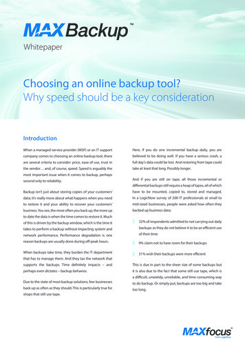
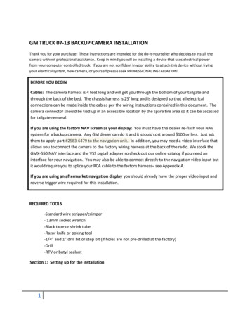
APPENDIX AWire the backup camera directly to your vehicle navigation wiring harness.The simplest and most robust option for interfacing your navigation is with a lockpick. You can choosefrom either a GMX-560 or GEN6 version, depending on your budget and needs. The lockpick will notonly allow you to interface your camera easily, but it will override all the features of your navigation thatare locked while in motion.The least expensive option is to purchase the CS-GMVSS1 or VSS2 interface harness to connect thecamera directly to your navigation system. For the VSS2 you will simply plug the brown connector intoyour radio and connect the camera RCA wire to the VSS connector.For the VSS1 connector you will need to insert 2 pins into your existing brown plug on the back of yourradio. To install, remove your radio to gain access to the wiring harness. Find the brown connector onthe back of your NAV radio and connect the leads as shown in the image below. There is a red plasticlock pin that goes through the center of the connector that will have to be pulled out before you canslide new pins into the brown connector. Wire the red video ( ) RCA wire to pin 6 and the black video(–) wire to pin 7 in your harness. The pin locations are numbered on the back of the plug so justremember that pin 8 is directly above pin 16, or just make sure you wire it as shown below:If you already have wires in these locations you can simply use a tap splice to tap into the existingwires.5
APPENDIX B2008-2012 Left I/P Junction Block (Typical)6
TROUBLESHOOTING:We will provide you with excellent support of your new camera. We just ask that try a few things beforecontacting us:1. Is the chassis harness still connected? Often times it can get pulled apart when pulling theharness toward the driver’s floor so check that first.2. Is the chassis harness connector properly seated to the camera connector? This is almostalways the problem so make sure the camera plug is pushed as far as it can go. Sometimes itmay be best to disconnect it and reconnect it again while pushing firmly to ensure it’s seated allthe way.3. Was your navigation properly re‐flashed for a backup cam? This is only required when using thefactory navigation. You should see a black screen with a banner across the top when in reverse.If not, call your dealer and have them re‐flash it.4. Do you have power at the camera when the truck is in reverse? Be sure to test the read lead atthe camera end FIRST. If you do not have power, check your connection or check the fusecovering the circuit you’re getting power from. Be careful not to touch multiple pins inside theconnection when power is applied. Test one pin at a time until you find the one with power (itshould be the lower left pin when looking into the connector with the orientation arrow on thetop.5. Do you have a good ground?6. Is the video RCA cable connected and secure at your receiver?7
If your truck didn't come with factory navigation but you installed it at a later time you may have purchased the CS-GMVSS2, which includes the entire brown VSS plug. In this case simply push the brown plug into the VSS slot in the back of your navigation radio and connect your camera RCA cable to the female RCA on this brown VSS adapter. 5.