Transcription
%0:6HUYLFH 7UDLQLQJ( ,QVWUXPHQW &OXVWHU6HPLQDU :RUNLQJ 0DWHULDO
NOTEThe information contained in this training course manual is intended solely forparticipants of the BMW Service Training course.Refer to the relevant "Technical Service" information for any changes/supplements to the Technical Data. 2001 BMW AGMünchen, Germany. Reprints of this manual or its partsrequire the written approval of BMW AG, MünchenVS-42 MFP-HGK-BRK-E85 1110
ContentsPageCHAP 1Instrument clusterIntroductionSystem overview- Input/output signals- System schematicIntroduction- New system features/modificationsComponents- Display areas- Indicator and warning lamps- LC display- Program and gear display- Acoustic generators- Setting buttonsSystem functions- Bus network- On-board computer- Distance to junction- Display in Multi-Information Radio- Redundant data storage (RDA)Country-specific version- Country-specific version: instrument clusterNotes for Service- Test functions- DiagnosisSIA IV service interval 37
E85 Instrument clusterInstrument clusterIntroductionInstrument cluster/SIAThe instrument cluster in the Z4 has a sporty appearance in linewith a roadster.The instrument cluster is very compact. The needle instrumentsare integrated in 2 housing attachments.The two needle instruments for the speedometer and therevcounter are thus the predominant visual features.The needle instruments for the fuel gauge and the coolanttemperature gauge are integrated in the revcounter.The speedometer incorporates an LC display, which shows e.g.the total mileage (odometer), the trip distance (trip odometer),the time, the on-board computer functions and the SIA serviceinterval indicator.Between the large needle instruments are the indicator andwarning lamps and the program and gear display.The program and gear display is only featured in vehicles withautomatic transmissions and SMG sequential manualgearboxes.The instrument cluster is the central gateway in the bus network.-1-
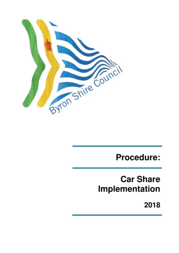
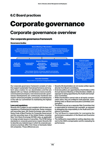
E85 Instrument clusterSystem overview- Input/output signalsInput signalOutput signalFig. 1:E85 System overview with input/output signals-2-KT-9915
E85 Instrument clusterIndexExplanationIndexExplanation1Handbrake switch10Ground supply, terminal 312Brake-lining wear sensors11Fuse-carrier withterminals 30, R and 153Coolant level switch12Outside-temperature sensor4DSC control unit13Fuel-tank sensor 15Oil-pressure switch(6-cylinder engine only,otherwise PT-CAN bus)14Fuel-tank sensor 26Axial button in steeringcolumn stalk for turn-signalindication15PT-CAN bus(Powertrain CAN bus)7Starter motor, terminal 30h16K bus (body electronics)8Reversing-light switch(for manual gearboxes only;otherwise signal fromgearbox control unit)17Diagnosis bus9Instrument cluster-3-
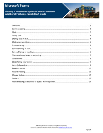
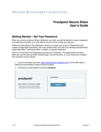
E85 Instrument cluster- System schematicFig. 2: E85 System schematic, instrument cluster-4-KT-9957
E85 Instrument ng wear sensor,front left11Handbrake switch2Digital Motor ElectronicsDME12Fuel-tank sensor 13Dynamic Stability ControlDSC13Fuel-tank sensor 24Outside-temperature sensor14Brake-lining wear sensor,rear right5Coolant level switchD-BusDiagnosis bus6Oil-pressure switch(6-cylinder engine only,otherwise PT-CAN bus)K-BusBody bus7Instrument clusterKl. 31Terminal 31 (ground)8Axial button, on-boardcomputer, in steeringcolumn stalk for turn-signalindicationKl. 30hStarter motor, terminal 509Reversing-light switch(for manual gearboxes only;otherwise signal fromgearbox control unit)PT-CANPowertrain CAN bus10Fuse-carrier withterminals 30, R and 15-5-
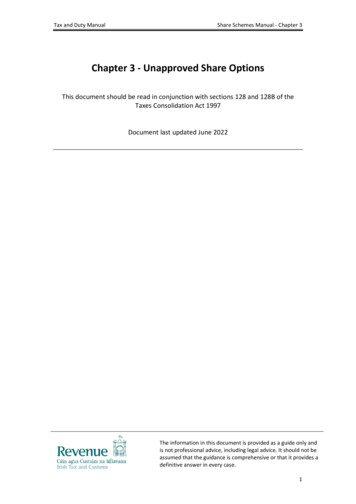
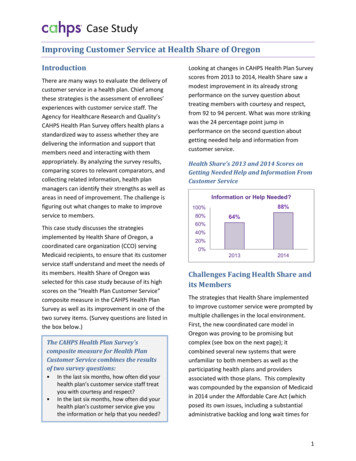
E85 Instrument clusterInstrument-cluster plug connectionThe 26-pin plug connection is located on the reverse side of theinstrument cluster.Fig. 3:IndexReverse side of E85 instrument clusterExplanation1Plug connection, plug connector, 26-pin2Sound opening, acoustic generator-6-KT-10498
E85 Instrument clusterIntroductionThis seminar working material contains descriptions of theinstrument cluster of the new Z4 (E85) scheduled for volumeproduction launch in 09/2002 (USA).The basis of these descriptions is the standard EU model.The USA-specific variations are described in the section headedCountry-specific version.- New system features/modificationsThe main feature of the instrument cluster in the new Z4 is itsnew design:Detail features are e.g. the positioning of the indicator andwarning lamps between the needle instruments.The coolant temperature gauge and the fuel gauge areintegrated in the revcounter.Additional indicator and warning lamps (e.g. Electric PowerSteering EPS) are integrated.The automatic gearbox or Sequential Manual Gearbox SMG hasa liquid-crystal display for indicating the gear.Some functions are new to the E85, e.g.:The instrument cluster of the Z4 has a gateway functionbetween the bus systems (as in the E46) K bus, PT-CAN busand diagnosis bus.The lighting of the instrument cluster is controlled by means ofthe K bus.The instrument cluster has a modified voltage supply withundervoltage detection.The acoustic alarms and test functions have been expanded.ComponentsThe instrument-cluster system comprises the following components:- Needle instruments- Indicator and warning lamps-7-
E85 Instrument cluster- LC display- Program and gear display for automatic gearbox and SMGSequential Manual Gearbox- Acoustic generator for outputting acoustic alarms- Acoustic generator for outputting turn-signal flasher rate- Two setting buttons, integrated in instrument cluster- Connected components which serve to activate the displays/indications in the instrument cluster (see system overview/system schematic)Note:The design and function of the components connected to theinstrument cluster (signal transmitters for activation) are notdescribed in closer detail.Special activation features are discussed in the description ofthe system functions.-8-
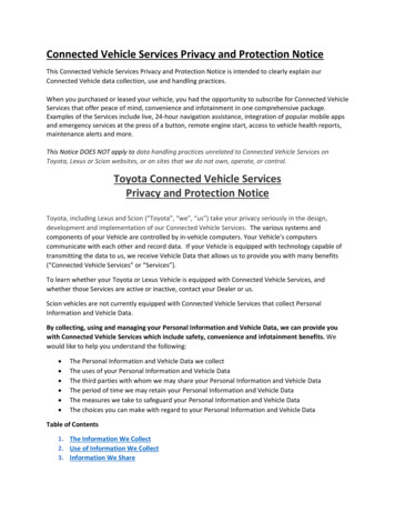
E85 Instrument cluster- Display areasThe instrument cluster is divided into the following displayareas:- Needle instruments- Indicator and warning lamps- LC display- Program and gear display for automatic gearbox and SMGSequential Manual GearboxFig. 4:KT-9916E85 Instrument cluster-9-
E85 Instrument clusterInstrument-cluster lightingThe speedometer and the revcounter are illuminated by slit lightbetween the dial face and the graduated dial.The brightness of the dial-face, needle and display illumination(dimming) is determined by the LSZ light switch centre.The lights ON signal is transmitted from the LSZ light switchcentre to the instrument cluster (via the K bus).The dimming signal is also transmitted via the K bus. The LSZevaluates the following input signals to control dimming:- Dimmer (knurl in light switch centre)- Photoelectric cell for ambient brightness (in light switchcentre)Because the dimming signal is sent via the K bus, there is noneed for terminal 58g.Instrument-cluster voltage supplyAn integrated power supply unit (switching controller) deliversthe supply voltage to the instrument cluster.The lighting of the instrument cluster is therefore not dependenton the vehicle electrical system and no fluctuations inbrightness can occur in the event of disturbances in theelectrical system.- 10 -
E85 Instrument clusterUndervoltage detectionThe instrument cluster incorporates an undervoltage-detectionfacility.Undervoltage detection is performed in the instrument clusterwith the aid of a comparator (software-based voltagecomparison).Note:Overvoltage in the electrical system is also detected.In the event of a system voltage 16 volts, it is possible e.g. for:- Inputs and outputs to be deactivated- Indicator and warning lamps to be deactivated or dimmed forthe duration of the overvoltageCoolant temperature gaugeIn the event of coolant overtemperature, a warning sound isissued when the red indicator and warning lamp lights up.The signal is delivered by the DME via the PT-CAN bus.Fuel gaugeThe indicator lamp is activated when the fuel reserve dropsbelow a threshold coded at the plant (standard 8 litres).- 11 -
E85 Instrument cluster- Indicator and warning lampsFig. 5:E85 Indicator and warning lampsKT-9963There are a total of 24 indicator and warning lamps in theinstrument cluster of the new Z4. The following two lamps arenew additions to the established lamps:- Indicator lamp for EPS: The Electric Power Steering system isused in the new Z4 for the first time.- Indicator lamp for lamp monitoring: This lamp indicates lampfailure in the headlights, rear lights and brake lights and isactivated by the light switch centre.The instrument cluster receives input signals through thefollowing channels:- Via the K bus- Via the PT-CAN bus- Directly from the sensorsAn overview of all the indicator and warning lamps is provided inthe following.- 12 -
E85 Instrument clusterOverview of indicator and warning lampsSymbolColour MeaningActivated byGreenLSZ (K bus)Turn-signal l R -Exception:Hazardwarning lights:Terminal 30KT-9969GreenTurn-signal flasher,rightLSZ (K bus)Terminal R -Exception:Hazardwarning lights:Terminal 30KT-9970RedBattery charge(terminal 61)DME (PT-CAN bus) Terminal 15 --BlueMain beam/lightsignalLSZ (K bus)RedLow oil pressureDME (PT-CAN bus) Terminal 15 1 s yellowand then(or oil-pressure1 s redswitch for6-cylinder engine)YellowLow oil levelDME (PT-CAN bus) Terminal 15KT-9971Terminal R --KT-9972KT-9973KT-9974- 13 -
E85 Instrument clusterSymbolPredriveCheckColour MeaningActivated byActivefromterminalYellowDSC via separatelineTerminal 15 2 sABS inactiveKT-9975General brakewarning light:RedParking brake( warning sound)Handbrake switch Terminal 15 1 s yellowand then1 s red(if coded)RedLow brake-fluid levelDSC (PT-CAN bus)RedEBV inactiveDSC (PT-CAN bus)YellowDBC inactiveDSC (PT-CAN bus) Terminal 15YellowBrake-lining wearBrake-lining wear Terminal 15 2 ssensors andalgorithm ininstrument clusterGreenFront fog lampsLSZ (K bus)KT-9976KT-9976KT-9976KT-9977KT-9978KT-9979- 14 -Terminal 15 -andterminal 58
E85 Instrument clusterSymbolPredriveCheckColour MeaningActivated byActivefromterminalGreenRear fog light(not USA)LSZ (K bus)Terminal 15 -andterminal 56YellowElectric PowerSteering EPSEPS (PT-CAN bus) Terminal 15 2 sYellowSystem failure orduring initialization(tyre change,inflation-pressurechange)DSC (PT-CAN bus) Terminal 15 1 s yellowand then1 s red(if coded)RedTyre-pressure lossRedAirbagASE (K bus)Terminal R 2 sRedFasten seat belts(country-specificcoding)ASE (K bus)Terminal 15 6 sYellowCheck Control(lamp fault)LSZ (K bus)Terminal 15 85- 15 -
E85 Instrument clusterSymbolPredriveCheckColour MeaningActivated byActivefromterminalYellowGearbox limp-homeprogramEGS/SMG(PT-CAN bus)Terminal 15 2 sYellowElectronic enginepower controlDME (PT-CAN bus) Terminal 15 --YellowMotor electronics(SERVICE ENGINESOON in USA)DME (PT-CAN bus) Terminal 15 --YellowASC (controlling orinactive)DSC (PT-CAN bus) Terminal 15 2 sYellowDTC controllingDSC (PT-CAN bus) Terminal 15 --YellowLow coolant levelCoolant levelswitchRedCoolant overtemperatureDME (PT-CAN bus) Terminal 15 2 sKT-9986KT-9987KT-9988KT-9989KT-9990Terminal 15 --KT-9991KT-9992- 16 -
E85 Instrument clusterSymbolColour MeaningActivated byActivefromterminalPredriveCheckYellowDME (PT-CAN bus) Terminal 15 -Open tank filler cap(CHECK FILLER CAP,USA only)YellowFuel reserveKT-9993Terminal 15 2 sFuel-tank sensorand algorithm ininstrument clusterKT-9994Explanation:ABS Anti-lock Braking SystemASC Active Stability ControlASE Advanced Safety ElectronicsCAN Controller Area NetworkDBC Dynamic Brake ControlDME Digital Motor ElectronicsDSC Dynamic Stability ControlDTC Dynamic Traction ControlEBV Electronic brake-force distributionEGS Electronic transmission controlEML Electronic engine-power controlLSZ Light switch centreMIL Malfunction Indication LightRPA Tyre defect indicatorPredrive CheckThe Predrive Check is a test of important indicator and warninglamps. In the Predrive Check, these indicator and warning lampsare activated for 2 seconds with terminal 15 ON.All the indicator and warning lamps are deactivated at the end ofthe Predrive Check.- 17 -
E85 Instrument cluster- LC displayThe LC display isintegrated in thespeedometer. It hasbeen adapted to theE85 instrument clusterand operates in thesame way as that ofthe E46.KT-9959Fig. 6: LC display (full dot matrix)- Program and gear displayIn cars fitted with anautomatic gearbox(5HP19) or an SMGSequential ManualGearbox, the programand gear display isfeatured in a separateLC display.KT-9964Fig. 7: E85 Program and gear displayIndex1ExplanationProgram modeIndex2ExplanationDrive positionThe LC display is located between the speedometer and therevcounter. With terminal 15 OFF, run-on operation is possibleprovided the SMG is still transmitting CAN telegrams.- 18 -
E85 Instrument cluster- Acoustic generatorsThe instrument clusterincorporates2 acoustic generators. The acousticrelay for the turnsignal flashers signalsthe flasher rate. Aninternal speakeroutputs all furtheracoustic alarms.KT-10313Fig. 8: E85 Acoustic generatorsIndex1ExplanationAcoustic relayIndex2ExplanationInternal speakerDepending on the incident, the acoustic alarms are output onceor intermittently.The following acoustic alarms are new:- Seat-belt reminder (for EU)The seat-belt reminder is issued by the instrument cluster aftera distance of 100 metres has been covered or during driving(possible through fitting of seat-belt buckles, which werepreviously only used in US vehicles)- Coolant overtemperature- Fuel-reserve thresholdSeat-belt reminder (for EU)The seat-belt reminder for EU is output for the first time for thedriver's and passenger sides. Here the SBE seat-occupancydetector identifies whether the passenger seat is occupied ornot.An intermittent acoustic alarm is triggered for max. 90 secondsafter a distance of 100 metres has been driven.The lock information is transmitted via the K bus.- 19 -
E85 Instrument clusterThe seat-belt reminder for USA is activated with terminal 15 ONif the seat-belt contact is not closed.The acoustic alarm is intermittent and lasts for max. 6 seconds.After this time has elapsed, only the indicator and warning lampremains lit.- Setting buttons2 setting buttons arelocated between the 2large needle instruments.KT-9965Fig. 9: Setting buttons in instrument clusterIndex1ExplanationLeft setting button(S/R for Set/Reset)The left button (S/R for Set/Reset) is used to reset the tripodometer reading, to call up thetest functions and to call up thereset menu for the serviceinterval indicator.Index2ExplanationRight setting button(clock symbol)The right button (clock symbol) isused to set the time and toswitch the service intervalindicator (remaining distance/service date or vice versa).NoteDetailed information can be found in the section headed Testfunctions and in the background material pertaining to theservice interval indicator.- 20 -
E85 Instrument clusterSystem functions- Bus networkThe instrument cluster is the central gateway (interface) for thebus network:The bus systems PT-CAN bus, K bus and diagnosis bus and thebyteflight are interconnected in the instrument cluster.KT-9917Fig. 10:E85 Bus network with instrument cluster as gatewayIndexExplanationIndexCDCCD changerNAV- 21 -ExplanationNavigation computer
E85 Instrument clusterIndexExplanationIndexExplanationCIDCentral Information DisplayPDCPark Distance ControlCVMSoft-top moduleDMEDigital Motor ElectronicsRLSDSCDynamic Stability ControlSBSLSatellite, B-pillar, leftEGSElectronic transmissioncontrolSBSRSatellite, B-pillar, rightEPSElectric Power SteeringSIMSafety and InformationModuleElectronic immobilizerSMSeat moduleEWS IIIRADIORadioRain/light sensorGM5General module 5SMGSequential Manual GearboxHIFITop hi-fi amplifier (DSP)SZMCentre-console switchcentreIHKAIntegrated heating andautomatic air conditioningTELTelephone control unitIHKSIntegrated heating and A/CcontrolVMVideo moduleIHSIntegrated heating control1Signal, ABS warning lampLSZLight switch centre2Distance-travelled signalLWSSteering-angle sensorThe byteflight is connected via the Safety and InformationModule SIM ( gateway) to the K bus.Instrument cluster as gatewayThe instrument cluster is the interface between K bus, PT-CANbus and diagnosis bus.The instrument cluster communicates with other control units inthe car via the K bus (single-core) or the PT-CAN bus(two-core).- 22 -
E85 Instrument cluster- On-board computerThe on-board computer functions are the same as those of theE46.A new feature in the E85 is the possibility of combining time andoutside temperature in the display depending on the equipmentspecification.In the Low version of the on-board computer, only the outsidetemperature is indicated in the LC display.The time is shown in the radio display.However, the time is still set using the button in the instrumentcluster.For vehicles without the radio option, there is no outsidetemperature display in the instrument cluster.Here the time is shown exclusively in the bottom line of theLC display.- Distance to junctionDistance to junction isthe display of thedistance to the nextjunction/turn-off. Thedistance is madeavailable by theinstrument-clusternavigation computervia the K bus.This distance displayin the instrumentcluster is restaggeredwhen the E85 is usedin conjunction with anavigation system(Low or High).KT-10501Fig. 11: Distance to junction displayIndex1ExplanationDistance to junction- 23 -
E85 Instrument cluster- Display in Multi-Information RadioIn cars with MultiInformation Radios(MIR), the on-boardcomputer functionsare also shown in theradio display.KT-10317Fig. 12: Multi-Information Radio (MIR)The average fuel consumption 2 on-board computer function isalso displayed. The rotary pushbutton can be used to scrollthrough the list.It is also possible to display the date.Settings (e.g. units or reset) which are made at the MIR using therotary pushbutton are sent by bus telegram to the instrumentcluster and updated.Date display: The date is administered in the instrument clusterand shown in the radio display.The current year is displayed after a power interruption (batteryreplacement). The year is stored in the instrument cluster.- 24 -
E85 Instrument clusterOn-board computer display in navigation-system on-boardmonitorIn cars equipped with the High navigation system, the on-boardcomputer functions are displayed in the pop-up on-boardmonitor (Central Information Display CID).The "Distance to junction" navigation data is displayed in parallelin the instrument cluster.Fig. 13: E85 On-board computer display, navigation-system on-board monitorKT-10581Settings (e.g. units or reset) which are made at the navigationsystem controls using the rotary pushbutton are sent by bustelegram to the instrument cluster. The hitherto valid values arethereby updated.The date can be set at the navigation-system controls. The dateis administered in the instrument cluster and shown in the onboard monitor.- Redundant data storage (RDA)The kilometre reading/mileage and the data of the SIA serviceinterval indicator are stored redundantly in the following controlunits: instrument cluster, LSZ light switch centre and EWSelectronic immobilizer.The above-mentioned data are thus retained when the controlunits are replaced.- 25 -
E85 Instrument clusterCountry-specific version- Country-specific version: instrument clusterThe instrument cluster comes in 6 versions, distinctions beingmade between EU LHD, EU RHD and USA LHD vehicles.The instrument cluster is also different depending on thegearbox installed: Cars fitted with manual gearboxes do nothave a program and gear display.Instrument-cluster versions:- EU LHD vehicle for automatic gearbox or SMG: speedometerdial up to 260 km/h and program and gear display- EU LHD vehicle for manual gearbox: speedometer dial upto 260 km/h; no program and gear display- EU RHD vehicle for automatic gearbox or SMG: outerspeedometer dial up to 160 mph and a 2nd inner dial upto 260 km/h; with program and gear display- EU RHD vehicle for manual gearbox: outer speedometer dialup to 160 mph and a 2nd inner dial up to 260 km/h; noprogram and gear display- USA version for automatic gearbox or SMG: speedometer dialup to 160 mph and a 2nd inner dial up to 260 km/h; withprogram and gear display and slightly different indicator lamps(see country-specific versions)- USA version for manual gearbox: speedometer dial up to160 mph and a 2nd inner dial up to 260 km/h; no program andgear display (see country-specific versions)- 26 -
E85 Instrument clusterEU right-hand driveDifference from EU left-hand drive: The scale of the speed dial isin both mph (miles per hour) and km/h (kilometres per hour).Fig. 14:E85 EU RHD instrument clusterKT-9966- 27 -
E85 Instrument clusterUSADifference from EU left-hand drive: The scale of the speed dial isin both mph (miles per hour) and km/h (kilometres per hour).Fig. 15:E85 USA instrument clusterKT-9967There are also differences in the indicator and warning lamps:- ABS symbol is replaced by ABS caption- General brake warning light symbol is replaced by BRAKEcaption- Check Engine symbol is replaced by SERVICE ENGINE SOONcaption- Additional indicator and warning lamp with CHECK FILLERCAP caption- 28 -
E85 Instrument clusterAcoustic alarmsThere are country-specific differences in the acoustic alarms.In USA cars, an ignition-key alarm is issued.In Gulf State cars, a single warning sound is issued when thecoded speed is exceeded (limit warning).Ignition-key alarm for USA cars: An intermittent warning soundis issued when the driver's door is opened with terminal 15 OFFand the ignition key still in the ignition lock.The warning sound is discontinued by removing the ignition key,by closing the driver's door or after a continuous alarm of30 minutes duration.Limit warning for Gulf State cars: A single warning sound isissued when the statutory speed threshold of 120 km/h isexceeded.The next speed warning can only be triggered when the speedthreshold has been undershot once by more than 4 km/h.The seat-belt reminder for USA is activated with terminal 15 ONif the seat-belt contact is not closed.The acoustic alarm is intermittent and lasts for max. 6 seconds.After this time has elapsed, only the indicator and warning lampremains lit.Note: reversing alarm and ranging alarm for JapanThe acoustic reversing alarm and the ranging alarm are outputfor Japan by means of the external gong.- 29 -
E85 Instrument clusterNotes for Service- Test functionsThe test functions are used by service mechanics to check thecoding. They also provide help in troubleshooting without thediagnostic tester.The test functions are only shown in the instrument-cluster LCdisplay.The test functions are activated by pressing the left settingbutton in the instrument cluster (S/R, 5 seconds) with terminal Ror terminal 15 ON.In addition, the test functions can still be called up by pressingthe left setting button (S/R for Set/Reset) in the instrumentcluster with simultaneous activation of terminal R.KT-10318Fig. 16:E85 Example: test function outside temperature (test function 7.1)The test functions are shown in the odometer and trip-odometerdisplay areas in the top line of the display.The display of the on-board computer function is retained in thebottom display line.- 30 -
E85 Instrument clusterTest function 19: locking and unlocking test functionsOnly the first two test functions are freely accessible.All further test functions are locked from the third test function.The lock can only be removed by means of test function 19.In test function 19, the display switches in intervals of 1 secondfrom L on to L oFF (Lock on and Lock off).The test functions are unlocked or locked by pressing the leftsetting button (S/R for Set/Reset).Unlocking test functionsIf while L oFF is displayed the left setting button (S/R for Set/Reset) in the instrument cluster is pressed, the test functionsremain unlocked or are unlocked.The display jumps to test function 0.Locking test functionsIf while L on is displayed the left setting button (S/R for Set/Reset) in the instrument cluster is pressed, the test functionsremain locked or are locked.The test functions must otherwise always be locked by means ofthe test function 19.Note:The test functions are always locked after a terminal has beenchanged.- 31 -
E85 Instrument clusterTerminating test functionsThe test functions are terminated by terminal R OFF.With terminal R ON, the test functions are exited by:- Pressing the left setting button (S/R for Set/Reset) for longerthan 5 seconds- Calling up the test function 21Overview of test functionsTest functionDescriptiontESt 0.Exit test functiontESttESttESttESttESttESttESttESttEStInfo roll- VIN, last 5 digits- K-number (speed)- BMW part number- Coding, diagnosis, bus indexes- Date of manufacture, calendar week/year- Hardware status/software status- EEPROM checksum status- CAN index CAN11Hex1.1.01.11.21.31.41.51.61.7tESt 2.tESt 2.0Visual system test- Display test, indicator and warning lamps, needle stepping motorstESt 3.tESt 3.0tESt 3.1Data service interval indicator SIA- Litres SIA- Days SIAtESt 4.tESt 4.0tESt 4.1Current consumption- Current consumption l/100 km- Current consumption undamped l/htESt 5.tESt 5.0tESt 5.1Range- Range consumption l/100 km- Range current kmtESttESttESttESt6.6.06.16.2Fuel level- Tank sensor, left/right litres- Tank sensor, averaged sum total litres- Fuel gauge, tank phase litrestESttESttESttESttESt7.7.07.17.27.3Current display values- Coolant temperature ºC- Outside temperature ºC- Engine speed rpm- Driving speed km/h- 32 -
E85 Instrument clusterTest 8.3ADC values- ADC system voltage- ADC tank sensor, left/right- ADC brake-wear sensors- ADC outside-temperature sensortESttESttESttESttESt9.9.09.19.29.3System voltage- System voltage- Voltage, power supply unit (switching controller)- ADC brake-wear sensors- ADC outside-temperature sensortESttESttESttESt10.10.010.110.2CAN monitor- DSC- DME- DME4tESt 11.Not usedtESt 12.Not usedtESt 13.tESt 13.0Test acoustic generators- Trigger single sound for testtESt 14.Not usedtESt 15.I/O ports processortESt 16.tESt 16.0Fault memory- Number of entered faultstESt 17.Not usedtESt 18.Not usedtESt 19.tESt 19.0Lock- Lock on/offtESt 20.Not usedtESt 21.tESt 21.0System (software)- Reset instrument cluster- 33 -
E85 Instrument clusterVisual system testFig. 17:E85 Test function 2, visual system testKT-10319In the visual system test, all the indicator lamps and lights - withthe exception of the ABS warning lamp - are activated briefly.The needle instruments are moved from the lower to upper stopand back again.- 34 -
E85 Instrument cluster- DiagnosisComponent replacement and trial replacementThere are three possible combinations for replacing theinstrument cluster/light switch centre:- Instrument cluster faulty, light switch centre OK- Light switch centre faulty, instrument cluster OK- Light switch centre and instrument cluster must be replacedSimultaneous replacement of the light switch centre and theinstrument cluster must be avoided. The odometer reading willbe lost.In principle it is also possible to carry out a trial replacement ofthe instrument cluster/light switch centre.Note:The exact procedure for component or trial replacement isdescribed in the E46 Trainer's Guide.- 35 -
E85 Instrument clusterCar & key memoryThere are different car-memory functions for the E85 with regardto the display of units in the instrument cluster.Car memorySettingExplanationConsumptionl/100 kmmpg (UK)mpg (US)km/lThe clock must be reset after the unitdisplay has been changed.DistancekmmlsTime12 h24 hTemperatureDegrees CelsiusDegrees FahrenheitBasic settingice warningActive/not activeAM/PM is also displayed in 12 h mode.Active:If the outside temperature drops belowapprox. 3 ºC the acoustic ice warning isissued and the outside temperature isdisplayed flashing for several seconds.The display then reverts automatically tothe previous display.Not active:If the outside temperature drops below 3 ºC the acoustic ice warning is issued.The outside-temperature display isdisplayed permanently.Pressing the axial button on the steeringcolumn stalk switches to the next display(average consumption).- 36 -
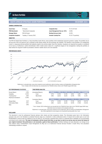
E85 Instrument clusterSIA IV service interval indicatorThe present SIA IV is the service interval indicator to be found inthe current E46.Diagram of reset routine for service interval indicatorInitial stateTerminal R andterminal 15 OFFKeep left buttonpressed andterminal R ONDisplay:Test functionNoButton pressed 5 secondsYesMenuTest function 1.0Display:Service statusYesDisplay:Service status(with rESEt)Litre limit forreset reachedNoNoNoDisplay: Servicestatus, rESEtflashes at 1 HzButton pressed 5 secondsNoButton pressed?YesYesNoYesPerformSIA resetYesTime-basedinspectioncoded?NoFlashed5 times?Button pressed?Display oldstatus for5 secondsDisplay newstatus for5 secondsDisplay:Service statusDisplay:Service status(with rESEt)Days limit forreset reachedYesNoNoDisplay: Servicestatus flashesat 1 HzButton pressed 5 secondsNoButton pressed?NoYesYesFig. 18:Flashed5 times?YesPerformSIA resetYesTerm. RroutineButton pressed?NoDisplay newdate for5 secondsDisplay:End SIAfor 2 secondsE85 Reset routine diagramDisplay olddate for5 secondsKT-10024- 37 -
The instrument cluster of the Z4 has a gateway function between the bus systems (as in the E46) K bus, PT-CAN bus and diagnosis bus. The lighting of the instrument cluster is controlled by means of the K bus. The instrument cluster has a modified voltage supply with undervoltage detection. The acoustic alarms and test functions have been expanded.