Transcription
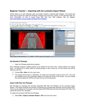
DATCOM Beginner’s Tutorial:Modeling a MiG-17The method of building a model is DATCOM can be immensely confusing. There are no point-and-click interfaceshere, only points in space. This tutorial aims at helping the novice user build a simple DATCOM model and test it. Thenumbers obtained may not be correct, but the model should be fairly accurate (except for a few assumptions).THE MIKOYAN-GUREVICH MIG-17In 1949, the Mikoyan-Gurevich (MiG) design bureau began work on a new fighter to replace theMiG-15. Two features of the aircraft were a thinner wing of greater sweep and a redesigned tail thatimproved stability and handling at speeds approaching Mach 1 (speed of sound). Although similarin appearance to the MiG-15, the MiG-17 has more sharply swept wings, an afterburner, betterspeed and handling characteristics and is about three feet longer. The wings of the aircraft are midmounted, swept-back, and tapered with blunt tips. They have wide wing roots. The engine is oneturbojet inside the body and has a round air intake in the nose. It has a single, small exhaust. Thefuselage is short, thick, cigar-shaped and tapered to the rear. It has a blunt nose and bubble canopy.The tail fin is swept-back and tapered with rounded tip. Flats are high-mounted on the tail fin,swept-back, and tapered. Flats and fin overhang the exhaust. (GlobalSecurity.org)The MiG-17 was chosen for this tutorial because of its simple design. The fuselage cross-section isalmost circular (and assumed to be), the wing shape is not complex, and the tails are not complex.DRAWINGS AND DIMENSIONSThe most difficult aspect of this project wasfinding adequate drawings of the aircraftwhich could provide accurate and consistentmeasurements. Eventually a drawing similarto the 3 view drawing pictured here wasfound. We can use the fact that MIG-17 has awingspan of approximately 31 feet 7 inchesand a length of 36 feet 5 inches to scale thedrawing and get the dimensions needed.It can be found (online) that the sweep of thewing and horizontal tail is 45 deg(approximately). The sweep of the largeFigure 1: MiG 17 Viewsdeg and the incidence is 1 deg.vertical tail is taken to be 55 deg, although itmay not be. The dihedral of the wing is -3As stated before, the fuselage cross section is conveniently circular, and for several stations,constant. It should be noted that the canopy was not implemented in the tutorial, which couldpossibly have affected the results (unimportant though).A major hindrance of the project, however, is the airfoil. The MIG uses a TsAGI S-12 (12%) airfoilshape. Since planes don't fly without wings, and the airfoil shape has a profound impact on flight,the selection of the airfoil is critical. Furthermore, the Digital Datcom does not account for Russian1
airfoils, so the assumption that a TsAGI S-12 (12%) is equivalent to a NACA 66-012 was made.Justification: none (aside from unverified information online). Since the data for TsAGI airfoils arenot readily available, the characteristics cannot be inputted manually into DATCOM, therefore weare left having to make this assumption.WRITING THE for005.dat FILEIt would be wise to read section 3 (Definition of Inputs) of volume I of the Digital DATCOM manual,especially 3.1 and 3.2, to familiarize yourself for what is coming next.The for005 file (aka input file) defines the flight characteristics and geometry of the aircraft. Itfollows a very specific format and any deviance for the format will cause the analysis not to be run.First we input the CASEID on the first line:CASEID MIKOYAN-GUREVICH MiG-17Every piece of data that defines the flight characteristics and geometry of the aircraft is contained innamelists. In the input file, namelists are preceded by a " " sign (ex. FLTCON) and the statementsare terminated with " " signs. For this exercise we will use the following namelists:FLTCON - defines the flight conditionsSYNTHS - locates the cg, wing, horizontal tail, and vertical tail with respect to a referencelineBODY - defines the body geometryWGPLNF - defines the wing planform geometryHTPLNF - defines the horizontal tail geometryVTPLNF - defines the vertical tail geometryTHE FLTCON NAMELISTThe FLTCON namelist defines the flight conditions such as Mach number(s), altitude(s), and angleof attacks to be analyzed. A full list of the inputs can be found on page 27 of the Digital Datcommanual volume I. We will use the following variables from the FLTCON namelist:NMACH - number of Mach numbers to be run. We will only run at one Mach.MACH - the aformentioned Mach numbers to be run. We will run at Mach 0.60.NALPHA - the number of angles of attack to test. We will test at 10 AOA's.ALSCHD - the schedule of angles of attack. We will use (in deg): -4, -2, 0, 2, 4, 6, 8, 10, 12, 14(ten total)NALT - number of altitudes to run. We will test only one altitude.ALT - the altitudes to run. We will test at 5000 feet.WT - the weight of the aircraft. We will use 13395 lbs for the MiG.LOOP - we will set to 1. A discussion of the important LOOP parameter will be presented atsome other time.2
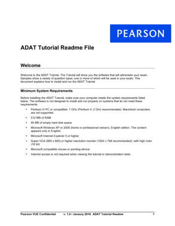
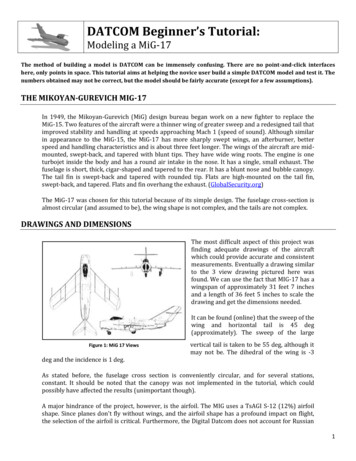
We can input these variables into the FLTCON namelist. Note that each number must contain adecimal point. Also, the file can only be a certain number of characters in horizontal length, so donot go over. The order in which the variables are given are not crucial, but the following format isrecommended. The following describes what goes into the input file: FLTCON NMACH 1.0,MACH(1) 0.6,NALPHA 10.0,ALSCHD(1) -4.0,-2.0,0.0,2.0,4.0,6.0,8.0,10.0,12.0,14.0,NALT 1.0,ALT(1) 5000.0,WT 13395.0,LOOP 1. THE SYNTHS NAMELISTThe SYNTHS (Synthesis) namelist is very important because it sets up the c.g. location as well as theposition of the wing and tail surfaces. So at this point you should know the dimensions of theaircraft pretty well. Page 33 in Datcom Volume I indicates exactly what dimensions you will need.All horizontal measurements will be taken from the nose of the aircraft. All vertical measurementswill be taken from a reference line conveniently placed at the center of the aircraft. The followingvariables from the SYNTHS namelist will be used:XCG - the horizontal position of the c.g. Since information of the c.g. position is not given, ac.g. position of 11.17 ft. was arbitrarily chosen (probably not right).ZCG - the vertical position of the c.g. with respect to the reference line. Arbitrarily chosen as0 feet.XW - the horizontal position of the apex of the wing. Measured as 3.63 feet.ZW - the vertical position of the wing apex wrt the reference line. Measured as 0.42 feet.ALIW - the incidence of the wing in degrees. For the MiG, this is 1 degree.XH - the horizontal position of the apex of the horizontal tail. Measured as 28.73 feet.ZH - the vertical position of the horiz. tail apex wrt the reference line. Measured as 5.24 feet.ALIH - incidence of the horizontal tail. No data found for the MiG, so taken as 0 degrees.XV - the horizontal position of the apex of the vertical tail. Measured as 18.3 feet.ZV - the vertical position of the vertical tail apex wrt the reference line. Since this lies on thereference line, it is 0 feet.These numbers can be inputted into the SYNTHS namelist: SYNTHS XCG 11.17,ZCG 0.0,XW 3.63,ZW 0.42,ALIW 1.0,XH 28.73,ZH 5.24,ALIH 0.0,XV 18.3,ZV 0.0 The following drawings will give the dimensions that will be used in this namelist and thesubsequent ones.3
Figure 2: Right Side View of MiGFigure 3:Top View of MiG4
THE BODY NAMELISTNow we can start modeling the components. First, we'll start with the body. As stated previously,we will forget the canopy and model the fuselage as having a circular cross section at each station.Note that in the drawing above, we have 8 stations starting with the nose and concluding at the rearsection of the fuselage. We will need the horizontal distance from the nose at each station (Xdistance) as well as the cross sectional area at each station. The numbers are tabulated below:StationX (feet)R (radius, feet)S (area, feet 830.770.692.5The variables of the namelist BODY that we will use are:NX - number of body stationsX - horizontal distance of each stationS - cross sectional area at each station(Technically we could use "R" instead of "S", but there are problems with that later on)With all of these values know, we can fully define the fuselage. The data is inputted as follows: BODY NX 8.0,X(1) 0.0,0.74,8.35,13.14,19.35,24.41,28.41,30.77,S(1) 5.19,9.32,16.89,16.89,15.94,11.12,5.85,2.5 THE WGPLNF NAMELISTNow we can define the wing planform using the WGPLNF namelist. Datcom volume I page 37 and38 can be extremely helpful for all of the planforms. The drawings above fully prescribe the wingplanform shape. The following are the variables we will use in defining the wing:CHRDTP - the length of the chord at the tip of the wing. Measured to be 7.02 feet.SSPNOP - the "Semi-Span outboard panel" which is "b*o/2" in the drawing. If the wing hastwo sections, like the MiG, there is an inboard panel and an outboard panel. This dimensionis taken from the demarcation of the two panels to the tip chord. Measured to be 11.32 feet.SSPNE - the "exposed" semi-span, which is the "b*/2". This dimension is from the side of thefuselage to the tip chord. Measured to be 13.41 feet.SSPN - the theoretical semi-span, which is b/2. This dimension is from the root chord to thetip chord. Measured to be 15.71 feet.CHRDBP - the chord at the break point between the inboard and outboard panel (the "cb"in the drawing). Measured to be 8.4 feet.CHRDR - the length of the chord at the root of the wing. Measured to be 14.0 feet.SAVSI - the sweep of the wing at the inboard panel (refer to the manual). Although thesweep of the MiG differs from the inboard to the outboard panel, we will take this asconstant and keep it as 45 degrees.SAVSO - the sweep of the wing at the outboard panel. A stated before, it will be 45 deg.5
TWISTA - the twist angle of the wing (wash-out). For the MiG, it is 0 deg.CHSTAT - the % of the mac at which the sweep angle will be referenced. Usually this is c/4or 0.25.DHDAHI - the dihedral of the inboard panel. If the inboard and outboard panel dihedral isthe same (constant dihedral across the wing), then only DHDADI is inputted. For the MiG,the wing dihedral is -3 deg.TYPE - different planform types (refer to manual). Will be set to 1.These values are inputted into the for005 file as follows: WGPLNF CHRDTP 7.02,SSPNOP 11.32,SSPNE 13.41,SSPN 15.71,CHRDBP 8.4,CHRDR 14.0,SAVSI 45.0,SAVSO 45.0,CHSTAT 0.25,TWISTA 0.0,DHDADI -3.0,TYPE 1.0 THE HTPLNF NAMELISTThe horizontal tail is described the same way as wing using the same variables. Because thegeometry of the HT is simpler, we will only use the following variables: CHRDTP, SSPNE, SSPN,CHRDR, SAVSI, CHSTAT, and TYPE.CHRDTP is 1.86 feetSSPNE is 5.42 feetSSPN is 5.43 feetCHRDR is 4.69 feetSAVSI is 45 degreesCHSTAT is 0.25TYPE is 1And so the values are inputted into the HTPLNF namelist as follows: HTPLNF CHRDTP 1.86,SSPNE 5.42,SSPN 5.43,CHRDR 4.69,SAVSI 45.0,CHSTAT 0.25,TYPE 1.0 THE VTPLNF NAMELISTThe vertical tail is described the same way as wing using the same variables. Because the geometryof the VT is simpler, we will only use the following variables: CHRDTP, SSPNE, SSPN, CHRDR, SAVSI,CHSTAT, and TYPE.CHRDTP is 3.76 feetSSPNE is 6.05 feetSSPN is 8.18 feetCHRDR is 12.47 feetSAVSI is 55 degrees (not measured)CHSTAT is 0.256
TYPE is 1And so the values are inputted into the VTPLNF namelist as follows: VTPLNF CHRDTP 3.76,SSPNE 6.05,SSPN 8.18,CHRDR 12.47,SAVSI 55.0,CHSTAT 0.25,TYPE 1.0 AIRFOIL DESIGNATIONSWe cannot forget to input the airfoil shapes for the wing and tails. Page 74 and 75 of volume I hassome information on this. If the wing was a NACA-2412, we would input into the for005 file: NACAW-4-2412. The "NACA" indicates that it is a NACA airfoil, for which DATCOM has built in data. "W"indicates that the airfoil is to be applied to the wing ("H" for HT, and "V" for VT). "4" indicates that itis a 4 series airfoil (DATCOM accepts 1, 4, 5, and 6 series airfoils). And after that is the airfoildesignation number, in this example it is "2412."For the MiG, the NACA 66-012 airfoil we be used for the wing, and the 66-009 for the tails. They willsimply be inputted into DATCOM as 009TERMINATING THE FILEThere are a number of commands that can be placed at the end of the file to specify information andgive more data. We will use 3 commands:DIM FT - specifies that all of the dimension were given in feet and all out the output shouldbe in "English" unitsBUILD - show the data for all of the components. not just the aircraftPLOT - generate a plot file (for013.dat) to input into the MATLAB plotting programFinally, the file ends with "NEXT CASE". In the input file this looks like:DIM FTBUILDPLOTNEXT CASE7
THE FULL for005.dat FILEHere is the full input file that will be run by DATCOM.CASEID ----- MIKOYAN-GUREVICH MiG-17 ---- FLTCON NMACH 1.0,MACH(1) 0.6,NALPHA 10.0,ALSCHD(1) -4.0,-2.0,0.0,2.0,4.0,6.0,8.0,10.0,12.0,14.0,NALT 1.0,ALT(1) 5000.0,WT 13395.0,LOOP 1. SYNTHS XCG 11.17,ZCG 0.0,XW 3.63,ZW 0.42,ALIW 1.0,XH 28.73,ZH 5.24,ALIH 0.0,XV 18.3,ZV 0.0 OPTINS SREF 243.0 BODY NX 8.0,X(1) 0.0,0.74,8.35,13.14,19.35,24.41,28.41,30.77,S(1) 5.19,9.32,16.89,16.89,15.94,11.12,5.85,2.5 NACA-W-6-66-012 WGPLNF CHRDTP 7.02,SSPNOP 11.32,SSPNE 13.41,SSPN 15.71,CHRDBP 8.4,CHRDR 14.0,SAVSI 45.0,SAVSO 45.0,CHSTAT 0.25,TWISTA 0.0,DHDADI -3.0,DHDADO -3.0,TYPE 1.0 NACA-H-6-66-009 HTPLNF CHRDTP 1.86,SSPNE 5.42,SSPN 5.43,CHRDR 4.69,SAVSI 45.0,CHSTAT 0.25,TYPE 1.0 NACA-V-6-66-009 VTPLNF CHRDTP 3.76,SSPNE 6.05,SSPN 8.18,CHRDR 12.47,SAVSI 55.0,CHSTAT 0.25,TYPE 1.0 DIM FTBUILDPLOTNEXT CASEREFERENCESData and HistoryBlueprints of Mig-17, http://www.the-blueprints.comHistory, a/mig-17.htmHistory & Data, http://www.vectorsite.net/avmig15 2.htmlPictures, .suchoj.com/andere/MiG17/galerie.shtml8
This tutorial aims at helping the novice user build a simple DATCOM model and test it. The numbers obtained may not be correct, but the model should be fairly accurate (except for a few assumptions). THE MIKOYAN-GUREVICH MIG-17 In 1949, the Mikoyan-Gurevich (MiG) design bureau began work on a new fighter to replace the