Transcription
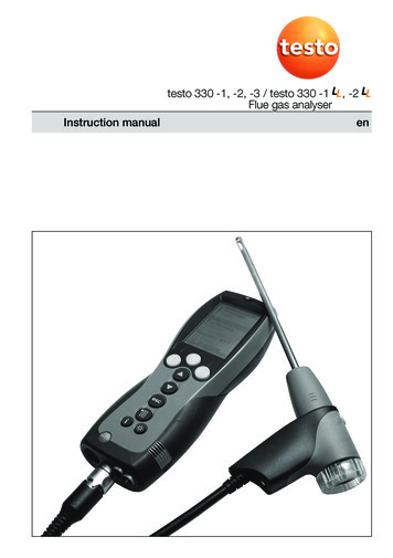
testo 330 -1, -2, -3 / testo 330 -1 , -2Flue gas analyserInstruction manualen
2 General notesGeneral notesPlease read this documentation through carefully and familiarise yourself with theoperation of the product before putting it to use. Keep this document to hand so thatyou can refer to it when necessary.The document describes the country-specific version D of the testo 330-1, -2, -3 andtesto 330-1 LL, -2 LL products.IdentificationSymbolMeaningWarning advice: Warning!Read the warning advice carefully and takeSerious physical injury could be caused if the the specified precautionary measures!specified precautionary measures are not taken.Important.(testo 330-1)TextThe description applies only for theinstrument indicated: testo 330-1, -2, -3 /testo 330-1 LL, -2 LL.Text appears on the instrument’s displayKeyPress the key.Function key with the function “OK”.Press function key.Short form for operating steps.See short form, p. 3.OKÞ xyzCommentsWarning advice: Caution!Read the warning advice carefully and takeSlight physical injury or damage to equipmentthe specified precautionary measures!could occur if the specified precautionarymeasures are not taken.Please pay particular attention.
General notes 3Short formThis document uses a short form for describing operating steps (e.g. calling up afunction).Example: Calling up the Flue gas functionShort form:Ý Measurements Ý OK Ý Flue gas Ý OK(1)(2)(3)(4)(5)Steps required:1 Open main menu:.2 Select Measurements menu:3 Confirm selection:OK.4 Select Flue gas menu:5 Confirm selection:OK,,.
4 ContentsContentsSee also Functional overview, p. 63.General notes . 2Contents . 4A.Safety advice . 7B.Intended purpose . 9C.Product description . 10C.1 Measuring instrument . 10C.1.1C.1.2C.1.3C.1.4C.1.5C.1.6C.1.7D.E.Overview . 10Keypad . 11Display . 11Device connections . 12Interfaces . 13Components . 13Carrying strap / barcode pen holder . 14C.2 Modular flue gas probe . 15Commissioning . 16Operation . 17E.1 Mains unit / rechargeable battery . 17E.1.1E.1.2E.1.3E.2Probes / Sensors . 19E.2.1E.2.2E.3Changing the battery . 17Charging batteries . 18Operation with the mains unit . 18Connecting probes / sensors . 19Replacing the probe module . 20Regular care . 20E.3.1E.3.2Condensate trap . 20Checking / replacing the particle filter . 21
Contents 5E.4Basic operating steps . 21E.4.1E.4.2E.4.3E.4.4E.4.5E.4.6E.4.7E.4.8F.E.5 Memory / Location . 25E.6 Instrument diagnosis . 27Configuration . 28F.1 Instrument settings . ing the measuring instrument on . 21Calling up a function . 22Entering values . 22Printing data . 23Saving data . 23Confirming an error message . 23Scanning locations with the barcode pen . 24Switching the measuring instrument off . 24Display edit . 28Printer . 29Alarm limits . 30Start Keys edit . 30t315-3 Connect. 31Communication . 32Date / Time . 32Language . 32F.2 Sensor settings . 33F.3 Fuels . 34Measuring . 35G.1 Preparing measurements . 35G.1.1G.1.2G.1.3G.1.4Zeroing phases . 35Using the modular flue gas probe . 36Configuring the reading display . 36Set memory/location . 36
6 ContentsG.2Measurements . nsfering data . 50H.1 Protocol printer . 50H.2 PC / Pocket PC . 50Care and maintenance . 51I.1Cleaning the measuring instrument . 51I.2Replacing measuring cells . 51I.3Recalibrating measuring cells . 52I.4Replacing additional filter . 52I.5Cleaning the modular flue gas probe . 53I.6Changing the thermocouple . 53Questions and Answers . 54Technical data . 55K.1 Standards and inspections . 55K.2 Measuring ranges and accuracies . 56K.3 Other device data . 57K.4 EC declaration of conformity . 58K.5 Principles of calculation . 59K.5.1K.5.2L.Flue gas . 37Draught . 38Fine pressure probe (accessory) . 38BImSchV (testo 330-3 / testo 330-2 LL) . 39Solid fuel measurement (testo 330-2). 41CO undiluted . 42Smoke No. / HCT . 42Differential pressure . 43Differential temperature . 44O2 air . 44Gas flow rate . 45Oil flow rate . 45Leak detection . 46Ambient CO . 46Ambient CO2 . 47Burner control . 48Fuel parameters . 59Calculation formulae . 59Accessories / Spare parts . 61Functional overview . 63
A. Safety advice 7A. Safety adviceAcid in the sensors. May cause chemical burns.Do not open the sensors. Eye contact: Rinse the affected eye thoroughly underrunning water for 10 minutes, keeping the eyelids wide open and protecting theunaffected eye. Remove contact lenses wherever possible.Acid in the sensor filters. May cause irritation to the skin, eyes or respiratory tract.Do not open the sensor filters. Eye contact: Rinse the affected eye thoroughly underrunning water for 10 minutes, keeping the eyelids wide open and protecting theunaffected eye. Remove contact lenses wherever possible.Skin contact: Remove the injured person’s contaminated clothing, ensuring selfprotection. Rinse affected skin areas under running water for at least 10 minutes.Inhalation: Move to fresh air and make sure that breathing is unrestricted.Ingestion: Rinse mouth out and spit out liquid. If conscious, drink 1 glass of water(approx. 200 ml). Do not induce vomiting.Avoid electrical hazards:Never use the measuring instrument and probes to measure on or near live parts!Protect the measuring instrument:Never store the instrument / measuring cells together with solvents (e.g. acetone). Donot use any dessicants.Product with BluetoothÒ (Option)Changes or modifications, which are not expressly approved by the responsible officialbody, can lead to a withdrawal of operating permission.Interference with data transfer can be caused by instruments which transmit on thesame ISM band, e.g. microwave ovens, ZigBee.The use of radio connections is not allowed in e.g. aeroplanes and hospitals. For thisreason, the following point must be checked before entering:Deactivate Bluetooth function:Ý Inst’ settings Ý OK Ý Communication ÝOKÝ IrDA ÝOK.Product safety / preserving warranty claims:Operate the measuring instrument only within the parameters specified in thetechnical data.
8 A. Safety adviceHandle the instrument properly and according to its intended purpose.Never apply force!Temperatures given on probes / sensors relate only to the measuring range of thesensors. Do not expose handles and feeders to any temperatures in excess of 70 C unless they are expressly permitted for higher temperatures.Open the measuring instrument only when this is expressly described in theOperating Instructions for maintenance purposes.Carry out only the maintenance and repair work that is described in the OperatingInstructions. Follow the prescribed steps exactly. For safety reasons, use onlyoriginal spare parts from Testo.The testo 330 must be checked before commissioning for any visible damage. Donot commission the testo 330 if there are signs of damage on the housing, mainsunit or supply lines. Electrical risk.
B. Intended purpose 9Any further or additional work must only be carried out by authorised personnel.Testo will otherwise refuse to accept responsibility for the proper functioning of themeasuring instrument after repair and for the validity of certifications.Ensure correct disposal:Dispose of defective rechargeable batteries and spent batteries at the providedcollection points.Send the measuring instrument directly to us at the end of its life cycle. We willensure that it is disposed of in an environmentally friendly manner.
10C. Product descriptionC.1 Measuring instrumentB. Intended purposeThis chapter describes the areas of application for which the measuring instrument isintended.The testo 330 is a handheld measuring device for the professional flue gas analysis offurnace systems:· Small furnaces (burning oil, gas, wood, coal)· Low-temperature and condensing boilersÀ Á· Gas heatersThese systems can be adjusted using thetesto 330 and checked for compliance withÂthe applicable limit values.The measuring instrument is approved formeasurements under the German regulationsÃon immissions protection (1. BImSchV).ÄÅÆÇÈÉThe following tasks can also be carried outwith the testo 330:· Regulating the O2-, CO- and CO2-, NO-,NOx values in furnaces for the purpose ofensuring optimal operation.· Draught measurement.· Measuring and regulating the gas flowpressure in gas heaters.· Measuring and optimising the flow andreturn temperatures of heating systems.· CO- and CO2 environment measurement.· Detection of CH4 (methane) andC3H8 (propane).testo 330 should not be used:· for continuous measurements· as a safety (alarm) instrumentThe testo 330 with the Bluetooth optionmay only be operated in countries inwhich it is type approved (see TechnicalData).
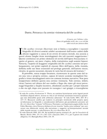
C. Product description11C.1 Measuring instrumentC. Product descriptionThis chapter provides an overview of the individual components of the product.C.1 Measuring instrumentC.1.1 OverviewÀ Switch on / offÁ Interfaces: USB, PS2, infraredDo not direct infrared beam athuman eyes. Condensate trap (on rear)à Fixing eyelets for carrying strap (left and right)Ä DisplayÅ Magnetic holders (on rear)ÀÁÂStrongmagnetsDamage to other magnetsÀÁÂÃ
12C. Product descriptionC.1 Measuring instrumentKeep safe distance fromÀÁÂÃÄproducts which could beÀÁÂÃdamaged by magnets (e.g.ÀÁÂ Ãmonitors, computers,pacemakers, credit cards).Æ Keypad
C. Product description13C.1 Measuring instrumentÇ Service cover (on rear)È Gas outletÀ Á Â ÃÉ Unit connections: flue gas probe, probe,pressure probe, mains unitÁÀÂÄÃÅ
14C. Product descriptionC.1 Measuring instrumentC.1.2 KeypadKeyFunctionsSwitch measuring instrument on / offFunction key (orange, 3x), relevant function is shown onÀthe displayScroll up, increase valueScroll down, reduce valueBack, cancel function Open Main menu: press briefly (changed settigs arestored, measurement values are carried over into themenu Flue gas); open Measurements menu: press andhold down for 2s (changed settigs are stored,measurement values are carried over into the menuFlue gas)ÁOpen Inst’ diagnosis menu Switch over display light: display light is permanentlyon or display light goes on for 10 seconds everytime akey is activated.C.1.3DisplayDepending on the menu that is active, the display shows a variety of elements.Header (active in all views)À Warning symbol (only if there is a device error;ÂÁÂÃthe device error isdisplayed in the Inst’ diagnosis menu).Active location.Power supply symbol:SymbolCharacteristicCharacteristic SymbolMains operationRech. battery operation, capacity: 26-50%Rech. battery operation, capacity: 76-100%Rech. battery operation, capacity: 6-25%Rech. battery operation, capacity: 51-75%Rech. battery operation, capacity: 0-5%Function select viewÀ Active menu, activated fuel
C. Product description15C.2 Modular flue gas probeÁ Selection field for functions:The chosen function is shown with a grey background.Unavailable functions are written in grey type.ÀÄÂ Scroll bar Å Ã Function keys for entering commandsÁÂÃ
16 D. CommissioningSettings viewÀ Active menuÁ Function fields for entering commands Scroll barà Selection field for adjustable values:The chosen value is shown with a grey background. Unavailable values are written ingrey type.Ä Function keys for entering commandsMeasuring viewÀ Active menu, depending on the chosen function: Additional information (e.g.activated fuel,date and time)Á Scroll bar Display field for readings, parametersà Function keys for entering commandsC.1.4 Device connectionsÀ Probe socketÁ Flue gas socket Mains unit socketà Pressure socket
E. Operation17E.1 Mains unit / rechargeable batteryC.1.5 InterfacesÀ USB interface:connection to PCÁ PS2 interface:connection to barcode pen, adapter for automatic furnaces Infrared interface (IrDA): connection to Ir/IrDA printers / Pocket PCà Bluetooth interface (option): connection to Bluetoothprinters / Pocket PCC.1.6 ComponentsÀ Rechargeable batteryÁ Measuring gas pump Slot for CO measuring cellà Slot for O2 measuring cellÄ Slot for NO-, NO low measuring cellÅ Additional filter
18E. OperationE.1 Mains unit / rechargeable batteryC.1.7 Carrying strap / barcode pen holderTo secure the carrying strap:1 Remove sealing caps from the sides of thehousing.Fix sealing caps on the inside of the service cover:1 Place the measuring instrument on its front.2 Pick the service cover up at the markings(arrows) using your index finger and thumb andpress gently to release the lock.3 Fold the service cover up and remove it.4 Secure the sealing caps in the two holders onthe inside of the service cover (À).5 Attach the service cover and engage it in place.2 Engage the carrying strap clip in the fixing eyelets on the side of the device. Note theguide groove. The strap must point “down” (Á).To secure the barcode pen holder to the carrying strap:1 Loosen the carrying strap at the buckle and remove.2 Lead carrying strap through the strap guide of the barcode pen holder (Â).3 Lead carrying strap through the buckle (Ã) and tighten.
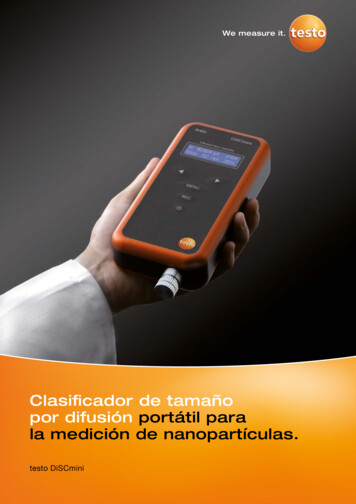
E. Operation19E.2 Probes / SensorsC.2 Modular flue gas probeÀ Removable filter chamber with window and particle filterÁ Probe handle Connecting cableà Connecting plug for measuring instrumentÄ Probe module lock releaseÅ Probe module
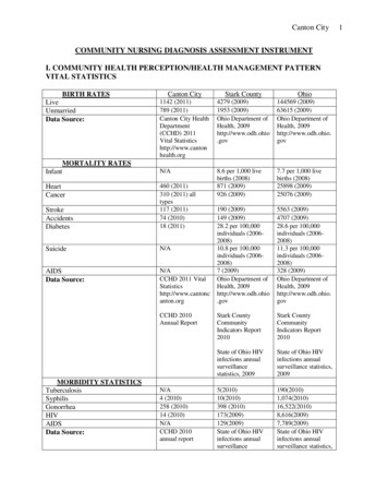
20E. OperationE.3 Regular careD. CommissioningThis chapter describes the steps required to commission the product.Remove the protective film from the display.The measuring instrument is supplied with a rechargeable battery already fitted.Charge the battery up fully before using the instrument (see Charging batteries,p. 18).ÀÁ
E. Operation21E.4 Basic operating stepsE. OperationThis chapter describes the steps that have to be executed frequently when using theproduct.Please read this chapter carefully. The following chapters of this document willassume you are already familiar with the content of this chapter.E.1 Mains unit / rechargeable batteryIf the mains unit is connected, the measuring instrument is automatically powered fromthe unit. It is not possible to charge the battery in the instrument during operation.E.1.1 Changing the batteryThe measuring instrument must not be connected to a mains socket via the mainsunit. The instrument must be switched off. Change the rechargeable battery within60 minutes so that device settings (e.g. date / time) are not lost.1 Place the measuring instrument on its front.2 Remove the service cover: Take hold of it at themarkings (arrows) using the index finger andthumb, press slightly, fold up and remove.3 Open the battery lock: Press the orange key andpush in the direction of the arrow.4 Remove the battery and insert a new rechargeablebattery. Only use the Testo rechargeable battery0515 0100.5 Close battery lock: Press the orange key and pushagainst the direction of the arrow until the batteryengages.6 Attach the service cover and engage it in place.
22E. OperationE.4 Basic operating stepsE.1.2 Charging batteriesThe rechargeable battery can only be charged at an ambient temperature of 0 to 35 C. If the battery has discharged completely, the charging time at room temperatureis approximately 5-6 h.Charging in the measuring instrumentThe instrument must be switched off.1 Connect the plug of the mains unit to the mains unit socket on the measuringinstrument.2 Connect the mains plug of the mains unit to a mains socket.- The charging process will start. The charge condition will be shown on the display.The charging process will stop automatically when the battery is fully charged.Recharging in the charging station (0554 1087)Refer to the documentation enclosed with the charging station.Battery careIf possible, always discharge the battery and recharge it fully.Do not store the battery for long periods when discharged. (The best storageconditions are at 50-80% charge level and 10-20 C ambient temperature; chargefully before further use).E.1.3 Operation with the mains unit1 Connect the plug of the mains unit to the mains unit socket on the measuringinstrument.2 Connect the mains plug of the mains unit to a mains socket.- The measuring instrument is powered via the mains unit.- If the instrument is switched off and a rechargeable battery is inserted, the chargingprocess will start automatically. Switching the instrument on has the effect ofstopping battery charging and the instrument is then powered via the mains unit.
E. Operation23E.4 Basic operating stepsE.2Probes / SensorsE.2.1 Connectingprobes / sensorsProbe socket:Probe detection is carried out at the socketduring the initial switch on activation process:Probes that are required must always beconnected before the meas uring instrument isswitched on, or the instrument must beswitched off and then on again after a change ofprobe, so that the correct data can be read intothe instrument.Flue gas socket:Probe / sensor detection at the flue gas socket is carried out continuously. It ispossible to change the probe / sensor even while the measuring instrument isswitched on.Connect flue gas probes / gas pressure adapters / temperature adapters Insert the connector into the flue gas socket andlock by turning it clockwise gently (bayonet lock). nly one hose extension (0554 1201) should beOconnected between the measuring instrument andthe flue gas probe.Connecting other probes Insert the connector of the probe into the probesocket.Connecting the pressure hose Fit the pressure hose on the connecting nipple ofthe pressure socket.
24E. OperationE.5 Memory / LocationE.2.2 Replacing the probe module1 Press the key on the top of the probe handle andremove the probe module.2 Fit a new probe module and engage it in place.E.3 Regular careE.3.1 Condensate trapThe fill level of the condensate trap can be read from the markings on the trap.A warning message ( red flashing light) is displayed if the level in the condensate trapreaches 90%.Emptying the condensate trapThe condensate consists of a weak mix of acids. Avoid contact with the skin. Makesure that the condensate does not run over the housing.Condensate in gas path.Damage to measuring cells and flue gas pump.Do not empty condensate trap while pump is operating.1 Hold the measuring instrument so that the condensate outlet points up.2 Open condensate outlet in condensate trap: Pull out approx. 5mm or until it will notgo any further (À).3 Let the condensate run out into a sink (Á).4 Dab off drops at condensate outlet using a cloth.5 Close the condensate outlet.
E. Operation25E.5 Memory / Location The condensate outlet must be fully closed (marking) otherwise incorrectmeasurements due to inleaking air may result.E.3.2 Checking / replacing the particle filterChecking the particle filter: Particle filters of the modular flue gas probe mustbe checked regularly for contamination:Check visually by looking through the window ofthe filter chamber.Replace the filter if there are signs ofcontamination.Replacing the particle filter:Filter chamber may contain condensate.1 Open the filter chamber: Turn gentlyanticlockwise.2 Remove the filter plate and replace it with anew one (0554 3385).3 Fit the filter chamber and lock it: Turn gentlyclockwise.E.4 Basic operating stepsE.4.1 Switching the measuring instrument on.- The start screen is displayed (for about 5 s).- Display illumination is switched on for 10 s.Option:To go directly to a measurement while the start screen is being displayed, pressthe function key for the desired measurement. See also Start keyconfiguration,p. 30.- The Measurements menu is opened.-or-
26E. OperationE.5 Memory / Location- If another probe / sensor is connected rather than a flue gas probe: the measuringmenu for that probe / sensor is opened.
F. Configuration27E.6 Instrument diagnosis-or- If the power supply was interrupted for a longer period: the Date / Time menu isopened.-or- There is an instrument error: Error diagnosis is displayed.E.4.2 Calling up a functionFunctions which cannot be selected, because the required probe/sensor is notconnected, are shown in grey type.1 Select the function:,.- The chosen function is shown with a grey background.2 Confirm selection:OK.- The chosen function is opened.E.4.3 Entering valuesSome functions require values (numbers, units, characters) to be entered. Depending onthe function that is chosen, the values are entered via either a list field or an input editor.List field1 Select the value to be changed (number, unit):,.2 Set the value:,.3 Repeat steps 1 and 2 as required.4 Confirm the input:OK.5 Save the input: OK Save input ÝOK.
28F. ConfigurationF.1 Instrument settingsInput editor1 Select the value (character):2 Accept the value:OK,,,.Options: To switch between upper-case / lower-caseletters: A a (not always available). To delete characters: . To position the cursor in the text: Select the textinput field: ,and position the cursor:,.To delete characters in front of the cursor:Del.3 Repeat steps 1 and 2 as required.OK4 Save the input: OK Save input Ý.E.4.4 Printing dataData are printed out via the function key Print . The function is only available if aprintout is possible.If data are to be transferred to a protocol printer via the infrared or Bluetooth interface,the printer that is to be used must be activated, see Printer, p. 29.E.4.5 Saving dataData are saved either via the function keyfunctions are only available if saving ispossible.Saveor the function field OK Save input. TheSee also Memory / Location, p. 25.E.4.6 Confirming an error messageIf an error occurs, an error message is shown in the display.To confirm an error message:OK.Errors which have occurred and have not yet been rectified are shown by a warningsymbol ( ) in the header.Error messages which have not yet been removed can be viewed in the Inst’ diagnosismenu, see Instrument diagnosis, p. 27.
F. Configuration29F.1 Instrument settingsE.4.7 Scanning locations with the barcode penLocations marked with barcode labels can be scanned using the barcode pen(0554 0461).1 Connect the connector of the barcode pen to the PS2 interface of the measuringinstrument.2Ý Memory / Location ÝOK.3 Scan the barcode: Hold the barcode pen over the white surface and then moveswiftly over the barcode label.- If the scanned barcode is already created as a location in the measuring instrument,this location is activated automatically.If the scanned barcode is not yet created as a location in the instrument, a newlocation is created.See also Memory / Location, p. 25.E.4.8 Switching the measuring instrument offUnsaved readings are lost when the measuring instrument is switched off.- Possibly: The pump starts and the measuring cells are rinsed until the shut-offthresholds (O2 20%, other parameters 50 ppm) are reached. Rinsing lasts nomore than 3 minutes.- The measuring instrument switches off.
30F. ConfigurationF.1 Instrument settingsE.5 Memory / LocationAll readings are allocated to the location that is activated at the time and can be saved inthe Flue gas menu. Unsaved readings are lost if the measuring instrument is switched off!Locations can be created, edited and activated. (Measuring) protocols can be printed.The special function Extras memory can be used to display the available memory. Allprotocols can be printed or deleted. The entire memory (locations and protocols) canalso be cleared.Calling up the function:Ý Memory / Location ÝOK.Creating a new location:Locations are identified by a unique location name. Each location name can only beallocated once.1 New location ÝOK.2 Select Location name Ýchange3 Enter values Ý OK Save input Ý.OK.4 Execute steps 2 and 3 for the other criteria accordingly (only testo
Do not commission the testo 330 if there are signs of damage on the housing, mains unit or supply lines. Electrical risk. 8 A. Safety advice . Any further or additional work must only be carried out by authorised personnel. Testo will otherwise refuse to accept responsibility for the proper functioning of the