Transcription
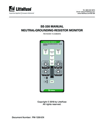
Tel: (800) 832-3873Email: 30 MANUALNEUTRAL-GROUNDING-RESISTOR MONITORREVISION 11-A-063018Copyright 2018 by LittelfuseAll rights reserved.Document Number: PM-1200-EN
SE-330 Neutral-Grounding-Resistor MonitorThis page intentionally left blank.Page iRev. 11-A-063018
SE-330 Neutral-Grounding-Resistor MonitorPage iiRev. 11-A-063018TABLE OF CONTENTS7 ORDERING INFORMATION. 341 GENERAL.11.1 Modern Resistance-Grounded Systems.11.2 SE-330 NGR Monitoring.11.3 NGR Short Detection.28 WARRANTY. 352 OPERATION.22.1 Settings.22.1.1 GF Trip Time.22.1.2 GF Trip Level.22.1.3 VN Trip Level.22.1.4 Pulse-Period Adjustment.32.1.5 Configuration Settings.42.1.5.1 Relay K1 Function (S1).42.1.5.2 Trip-Relay Mode andTrip-Memory Mode (S2).42.1.5.3 Ground-Fault-Trip Latch (S3).42.1.5.4 Resistor-Fault-Trip Latch (S4).42.1.5.5 Sensing-Resistor Selection (S5).42.1.5.6 Frequency (S6).42.1.5.7 Upgrade Mode (S8) .42.1.6 Resistor-Fault Trip Time.42.1.7 Resistor-Fault Trip Level .42.1.8 Geo-Magnetic Filter.42.2 Calibration.52.3 Pulsing Operation.52.4 Trip Indication and Reset.52.5 Remote Operation.52.6 Relay K1 LED.62.7 Unit Healthy Output.62.8 Diagnostic LED.62.9 Enhanced Health Status.62.10 Analog Output.63 INSTALLATION .63.1 SE-330.63.2 Sensing Resistor.123.3 Ground-Fault CT.203.4 Isolated Ground Connection.243.5 Pulsing Connection.244 DATA INTERFACES.254.1 SD Card.254.1.1 Datalogging.254.1.2 Firmware Upgrade.254.2 USB Interface.254.3 Network Communications.265 TROUBLESHOOTING.276 TECHNICAL SPECIFICATIONS.296.1 SE-330.296.2 Sensing Resistors.316.3 Current Sensors.329 TEST PROCEDURES. 359.1 Resistor-Fault Tests. 359.1.1 Calibration and Open Test. 359.1.2 Voltage Test. 359.2 Sensing-Resistor Test. 359.3 Analog-Output Test. 369.4 Ground-Fault Performance Test. 36APPENDIX A SE-330 REVISION HISTORY. 37LIST OF ation switches. 4Analog-output connections. 6SE-330 connection diagram. 7SE-330 outline and panel-mounting details. 8SE-330 outline and surface-mounting details. 9SE-IP65CVR-G weatherproof cover outline. 10SE-IP65CVR-G weatherproof cover installation. 11ER-600VC sensing resistor. 12SE-MRE-600 moisture-resistant enclosure outline. 13ER-600VC installed in SE-MRE-600. 14ER-5KV sensing resistor. 15ER-5WP sensing resistor. 16ER-15KV sensing resistor. 17ER-25KV sensing resistor. 18ER-35KV sensing resistor. 19ELCT5-88 and ELCT30-88 ground-fault current sensors. 21ELCT5-31 and ELCT30-31 ground-fault current sensors. 22RK-332 remote indication and reset. 23PGA-0520 analog percent current meter. 23Simplified isolated-ground connection. 24Simplified pulsing connection. 24Ground-fault test circuits. 36LIST OF TABLES123Typical tripping system values. 3Ground-fault trip levels for selected CTs. 3Ground-fault-test record. 36DISCLAIMERSpecifications are subject to change without notice. Littelfuse,Inc. is not liable for contingent or consequential damages or forexpenses sustained as result of incorrect application, incorrectadjustment, or malfunction.
SE-330 Neutral-Grounding-Resistor MonitorThis page intentionally left blank.Page iiiRev. 11-A-063018
SE-330 Neutral-Grounding-Resistor Monitor1. GENERAL 1.1 Modern Resistance-Grounded SystemsA high-resistance-grounded system uses a neutral-groundingresistor (NGR) with a low let-through current to limit the groundfault current. This is an improvement from low-resistance andsolidly grounded systems, which do not use NGRs and thereforehave a ground-fault flash hazard that can cause substantial pointof-fault damage. High-resistance grounding eliminates theseproblems. Modern ground-fault protection reliably operates at lowcurrent levels. Furthermore, the probability of an arc-flash incidentis significantly reduced in high-resistance-grounded systems.NGR selection depends on system charging current and whetherthe system is an alarm-only or a tripping system. Alarm-onlysystems are usually restricted to system voltages up to 5 kV withNGR let-through currents of 5 A or less. Occasionally, alarm-onlysystems up to 15 kV and 10 A are used, however, these systemsare not common because a ground fault on such a system tendsto escalate to a phase-to-phase fault before the ground fault canbe located and cleared. Consult Canadian Electrical (CE) Code rule10-302, National Electric Code (NEC)* 250.36, and NEC 250.186 forapplication details.System charging current is the capacitive current that flowsto ground when a bolted ground fault occurs. This current canbe calculated or measured. For small systems, the magnitude ofcharging current may be conservatively estimated as ½ A per 1,000kVA in low-voltage systems and 1 A per 1,000 kVA in mediumvoltage systems.In an alarm-only system or in a tripping system without selectivecoordination, use an NGR with a let-through current larger than thesystem charging current. Set the pick-up current of ground-faultdevices at or below 50% of the NGR let-through current.In a tripping system with selective coordination, use ground-faultdevices that have a definite-time characteristic to achieve timecoordination. Use the same pick-up current for all ground-faultdevices, which must be a larger value than the charging currentof the largest feeder. Select an NGR with a let-through currentbetween five and 10 times the pick-up current of the ground-faultdevices.Do not use a grounding transformer with a low-voltage resistor: The combined cost of a transformer and a low-voltage resistoris more than the cost of a resistor that is rated for line-toneutral voltage.A transformer can provide the inductance necessary to causeferroresonance if the NGR opens.Following these guidelines will reduce the flash hazard, reducepoint-of-fault damage, achieve reliable ground-fault protection, andensure a stable system not subject to ferroresonance.1.2 SE-330 NGR MonitoringThe SE-330 is a microprocessor-based NGR monitor that detectsNGR failures and ground faults in resistance-grounded systems andis compliant with the 2018 CE Code. The SE-330 measures NGRresistance, NGR current, and transformer or generator neutral-toground voltage. The components required to monitor an NGR arean SE-330, a 20- or 100-kΩ ER-series sensing resistor, and a currenttransformer (CT).Power-circuit elements (other than neutral-connected NGRs)that purposefully connect the power system to ground are oftennot compatible with SE-330 NGR monitoring. These elementsinclude single-phase grounding transformers, grounded-wyeprimary potential transformers, and grounded-wye-primary powertransformers.The SE-330 continuously measures NGR resistance in anunfaulted system. It will trip on resistor fault if the NGR resistancevaries from its calibrated value. When a ground fault occurs, voltageis present on the neutral. NGR current will flow if the NGR is healthy.The SE-330 will trip on ground fault if fault current exceeds the GFTRIP LEVEL setting for an interval equal to the GF TRIP TIME setting.However, if the NGR fails open during a ground fault, it is possiblefor fault resistance to satisfy the NGR resistance measurement. Todetect this double-fault condition, the SE-330 measures neutralvoltage. If neutral voltage exceeds the VN TRIP LEVEL setting and ifNGR current is less than 5% of the CT rating, the SE-330 will trip onresistor fault. If the resistor-fault circuit is tripped and the neutralvoltage exceeds the VN TRIP LEVEL setting for an interval greaterthan the GF TRIP TIME setting, the ground-fault circuit will also trip.Ground-fault current is sensed by a CT with a 1- or 5-A secondary,or by a CT (ELCT5-x or ELCT30-x) with a 50-mA secondary. The triplevel of the ground-fault circuit is adjustable from 2 to 100% of theCT rating. The trip time is adjustable from 0.1 to 10.0 seconds.The SE-330 has four output relays. With firmware version 3.00 orhigher, relays K1, K2, and K3 can be assigned to one of the followingfunctions (using SE-MON330 version 4.0 or higher): Ground Fault (GF);A transformer saturated by a ground fault through a rectifiercan make ground-fault protection inoperative. Resistor Fault (RF); Enhanced Health Status (HEALTH); Transformer inrush current up to 12 times the rated current cancause a voltage that is larger than expected. GF RF; A parallel transformer winding makes it difficult to monitorNGR continuity. GF RF HEALTH; or DISABLED. Page 1Rev. 11-A-063018
SE-330 Neutral-Grounding-Resistor MonitorIn addition to the selected function, K1 is also assigned a trip orpulsing function. When the pulsing function is selected, relay K1is used to control a contactor to assist in locating faults. RelaysK1, K2, and K3 can be set to operate in the fail-safe or non-failsafe mode for undervoltage or shunt-trip applications. Relay K4 is asolid-state relay that provides basic UNIT HEALTH indication.Additional features include LED trip indication, trip memory,front-panel and remote reset, 4-20-mA analog output, trip eventrecorder, USB local communications, microSD* data logging, andoptional network communications.The SE-330 provides additional features over the SE-330 legacymodel (revision 04 or less):Page 2Rev. 11-A-063018is not detected. A trip will eventually occur when the time for faultcurrent above the trip level is greater than the time for fault currentbelow the trip level.A non-accumulating mode can also be selected. In this mode, atrip occurs if the fault current remains higher than the ground-faulttrip level for the duration of the ground-fault trip time.2.1.2 GF Trip LevelThe SE-330 uses a Discrete-Fourier Transform (DFT) algorithm tomeasure the fundamental component of NGR current.Choose an NGR let-through current and a ground-fault triplevel using the guidelines in Section 1.1. Set the ground-faulttrip level between 2 and 100% of the CT-primary rating. Whenthe ground-fault trip level is set to MEM, the ground-fault settingthat is stored in non-volatile memory is used. This parametermust be set using a PC running the SE-MON330 software andconnected to the USB interface. The setting range is 2 to 100%of CT primary rating in 1% increments. The default value is 15%.Inputs are provided for 5-, 1-, and 0.05-A secondary CTs. Typicalvalues for 5-, 15-, and 25-A tripping systems are shown in Table 1.Ground-fault trip levels for the selected CTs are shown in Table 2.For other systems, refer to the NGR Monitor Set-Point Assistantat www.littelfuse.com/relayscontrols. The Set-Point Assistant isincluded with the SE-MON330 software. NGR short detection capability. Configurable output relay function and operating mode (K1,K2, and K3). When the trip level is set to MEM, the ground-fault trip settingis defined by an internal non-volatile memory variable. Therange is 2 to 100% in 1% increments of the CT-primary rating. The number of trip records has been increased to 100 andincludes date and time stamping. A microSD card interface can be used for short-term datalogging and firmware updates. A microSD card is included.See Section 4.1. For ease of connection to new devices, the RS-232 interfacehas been replaced by a Mini-B USB port.2.1.3 VN Trip Level Dual Ethernet ports are available with support for fiber-opticand RJ45 interfaces.The SE-330 uses a DFT algorithm to measure the fundamentalcomponent of neutral voltage (VN). An added IEC61850 protocol.The SE-330 will trip and indicate a resistor fault if neutral voltageis greater than the VN TRIP LEVEL setting for the duration of theresistor-fault trip time, and ground-fault current is less than 5% ofthe CT rating. If the resistor-fault circuit is tripped and the neutralvoltage exceeds the VN TRIP LEVEL setting for an interval greaterthan the GF TRIP TIME setting then the ground-fault circuit willalso trip.1.3 NGR Short Detection (firmware version 3.00 and higher)The SE-330 can be configured to monitor and trip if the NGRresistance decreases to a value less than 10 to 70% of the NominalNGR Resistance value. The Nominal NGR Resistance, NGR ShortTrip Level, and several other values can be configured using SEMON330 (version 4.0 or higher). Refer to the SE-MON330 manualfor further details.2. OPERATION2.1 Settings2.1.1 GF Trip TimeGF TRIP TIME (definite time) is adjustable from 0.1 to 10.0seconds. Time-coordinated ground-fault protection requires thissetting to be longer than the trip times of downstream ground-faultdevices.A trip-time accumulator provides a ground-fault memory functionfor detection of intermittent faults. The accumulated time increaseswhen a ground fault is detected and decreases when a ground faultThe VN TRIP LEVEL range is 20 to 2,000 V when switch S5 is in the20-kΩ (Vx1) position, and the range is 100 to 10,000 V when switchS5 is in the 100-kΩ (Vx5) position. Calculate the voltage across theNGR when the NGR current is equal to the pick-up current of theground-fault circuit. Set the VN TRIP LEVEL to the next largest value.See Fig. 1 and Section 2.1.5.5.Typical values for 5- 15-, and 25-A tripping systems are shownin Table 1. For an NGR resistance greater than 2 kΩ, use a 100-kΩsensing resistor. For other systems, refer to the NGR Monitor SetPoint Assistant at www.littelfuse.com/relayscontrols.NOTE: A resistor-fault trip is inhibited if the ground-fault current isabove 5% of the CT rating.
Page 3Rev. 11-A-063018SE-330 Neutral-Grounding-Resistor MonitorTABLE 1. Typical tripping system RESISTORSENSING RESISTORGROUND-FAULTTRIP LEVELVN TRIP ESISTANCE(SWITCH S5SETTING)(AMPERES)(VOLTS)480555ER-600VC20 kΩ1.060600569ER-600VC20 kΩ1.01002,4005277ER-5KV20 kΩ1.03404,1605480ER-5KV20 kΩ1.08004801518ER-600VC20 kΩ3.0606001523ER-600VC20 kΩ3.01002,4001592ER-5KV20 kΩ3.03404,16015160ER-5KV20 kΩ3.08007,20015277ER-15KV100 kΩ3.0170x5 85014,40015554ER-15KV100 kΩ3.0340x5 1,7004,1602596ER-5KV20 kΩ5.08007,20025166ER-15KV100 kΩ5.0170x5 85014,40025332ER-15KV100 kΩ5.0340x5 1,70025,00025577ER-25KV100 kΩ5.0800x5 4,00035,00025808ER-35KV100 kΩ5.01,200x5 6,000TABLE 2. Ground-fault trip levels for selected CTsGF 03201005.0030.0050100200400When set to MEM, range is 2 to 100% in 1% increments.* Setting not recommended.(1)2.1.4 Pulse-Period AdjustmentPulse period is the cycle time of relay K1 when the SE-330 isconfigured for pulsing operation. Pulse period is adjustable from 1.0to 3.0 seconds with a fixed duty cycle of 50 percent. For example,with the 1.0-s setting, relay K1 will be energized for 0.5 secondsand de-energized for 0.5 seconds when pulsing is enabled.See Section 2.3 for detailed pulsing operation information.NOTE: For pulsing configuration, set switch S1 to K1 PULSINGand install an external pulse-enable switch.
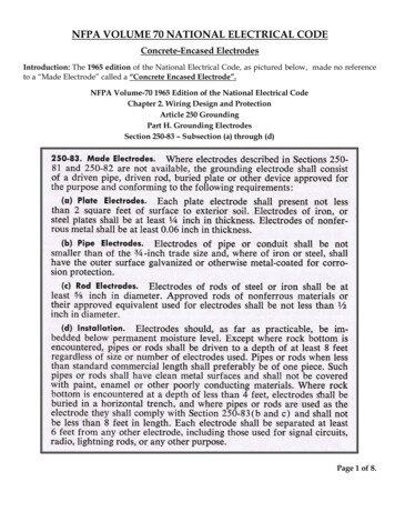
SE-330 Neutral-Grounding-Resistor MonitorPage 4Rev. 11-A-0630182.1.5 Configuration Settings2.1.5.3 Ground-Fault-Trip Latch (S3)Eight configuration switches (S1 to S8) and a calibration buttonare located behind the access cover on the front panel. See Fig. 1.Set switch S3 to select latching or non-latching ground-faultcircuit operation. Non-latching operation overrides ground-fault-tripmemory. See Sections 2.1.5.2 and 2.4.CALIBRATION BUTTONK1 TRIPK1 FAIL-SAFES1 K1 PULSINGS2 K1 NON-FAIL-SAFELATCHING GF TRIPS3 NON-LATCHING GF TRIPLATCHING RF TRIPS4 NON-LATCHING RF TRIP20 kΩS5 100 kΩ50 HzS6 60 HzNOT USEDRUNS7S8 UPGRADE2.1.5.4 Resistor-Fault-Trip Latch (S4)Set switch S4 to select latching or non-latching resistor-faultcircuit operation. Non-latching operation overrides resistor-faulttrip memory. See Sections 2.1.5.2 and 2.4.2.1.5.5 Sensing-Resistor Selection (S5)Set switch S5 to the resistance of the sensing resistor. For theER-600VC, ER-5KV, and ER-5WP, select 20 kΩ. For the ER-15KV, ER25KV, and ER-35KV, select 100 kΩ. Switch S5 sets the resistor-faulttrip value and the VN TRIP LEVEL range. See Section 2.1.3.2.1.5.6 Frequency (S6)NOTE:1. DEFAULT SETTINGS SHOWN.FIG. 1. Configuration switches.2.1.5.1 Relay K1 Function (S1)Set switch S1 to K1 TRIP to assign the trip function to relay K1and to activate switch S2. With the default setting, relay K1 willchange state when a resistor-fault or ground-fault trip occurs. Othertrip functions can be assigned to K1 using SE-MON330 software orvia network communications.Set switch S1 to K1 PULSING to configure relay K1 for pulsingoperation. See Section 2.3.2.1.5.2 Trip-Relay Mode And Trip-Memory Mode (S2)Set switch S2 to select the operating mode of trip relay K1. In thenon-fail-safe mode, relay K1 energizes and its contact closes whena trip occurs. The non-fail-safe mode can be used to trip shunt-tripcircuit breakers. In the non-fail-safe mode, SE-330 trips are resetwhen supply voltage is cycled.In the fail-safe mode, relay K1 energizes and its contact willclose if there are no trips. The contact will open in the event of atrip, a loss of supply voltage, or a processor failure. In the fail-safemode, SE-330 trips are not reset when the supply voltage is cycled.NOTE: Switch S2 does not affect the operating modes of relaysK2, K3, and K4.NOTE: Switch S2 only affects relay K1 operating mode when K1 isassigned the trip function (switch S1 set to K1 TRIP). Trip memoryis enabled when K1 is set to the fail-safe mode, regardless of theswitch S1 setting.Set switch S6 to 50 or 60 Hz to tune the digital filter to the linefrequency of the monitored system.2.1.5.7 Upgrade Mode (S8)The microSD card is used for firmware upgrades. See Section4.1.2 for upgrade instructions.NOTE: An upgrade causes an SE-330 restart and this may cycle theoutput relays.2.1.6 Resistor-Fault Trip TimeThe resistor-fault trip time can be adjusted from from 12 seconds(the default) to as much as 60 seconds using the SE-MON330software or via network communications.2.1.7 Resistor-Fault Trip LevelThe resistor-fault trip level can be adjusted using the SE-MON330software or via network communications. See Section 6.1.2.1.8 Geo-Magnetic FilterA low-frequency ground current can be caused by the Earth’smagnetic field and from charged clouds passing overhead duringa thunderstorm. In some conditions, this can cause a false resistorfault trip. Enabling the geo-magnetic filter and increasing theresistor-fault trip time can help counteract these effects.A trip time of 30 seconds is recommended when thegeo-magnetic filter is enabled.The geo-magnetic filter is disabled by default but can be enabledusing the SE-MON330 software or via network communications.
SE-330 Neutral-Grounding-Resistor MonitorPage 5Rev. 11-A-0630182.2 Calibration2.4 Trip Indication And ResetThe SE-330 measures the resistance change of the NGRrelative to the NGR-resistance value that was determined at thetime of calibration. When the resistance change is greater thanthe threshold amount (500 Ω for 20-kΩ systems and 2,500 Ω for100-kΩ systems), a resistor-fault trip will occur. The SE-330 shouldbe calibrated for new installations, or if the NGR or the sensingresistor is changed.Red LEDs and indication relays indicate ground-fault andresistor-fault trips. The indication relays K2 (default is GF) and K3(default is RF) operate in either fail-safe or non-fail-safe mode. Thedefault is non-fail-safe mode. In this mode, the relays are energizedwhen a fault occurs. The relay mode setting is stored in non-volatilememory and can be set using the SE-MON330 software or networkcommunications.NOTE: If the SE-330 is not calibrated and is supplied from the loadside of the breaker (non-fail-safe mode), calibrate it within theresistor-fault trip time after power-up or it may trip and interrupt itssupply. See Section 2.1.6.When a trip occurs with latching operation selected, theSE-330 remains tripped until the unit is reset with the front-panelRESET button or the remote-reset input. See Sections 2.1.5.3 and2.1.5.4. Terminals 15 and 16 are provided for remote reset asshown in Fig. 3. The reset circuit responds only to a momentaryclosure so that a jammed or shorted button does not prevent a trip.The front-panel RESET button is inoperative when terminal 15 isconnected to terminal 16. If non-latching operation is selected, tripsand corresponding indication will automatically reset when thefault clears. In addition, the power-up trip memory will be ignoredeven when configuration switch S2 is set to fail-safe. The maximumautomatic reset time is 2.8 s.The CALIBRATION button is located behind the access cover onthe front panel, and is recessed to prevent inadvertent activation.NOTE: Calibration must be performed with the SE-330 connectedto the sensing resistor and NGR of the installed system.To calibrate the SE-330, press and hold the CALIBRATIONbutton until the green CALIBRATED LED turns off and then turnson (if the LED is already off, press and hold down the button untilthe LED turns on). Calibration takes approximately two seconds.If calibration is not successful a resistor-fault trip occurs, theRESISTOR FAULT TRIP LED will be on, the CALIBRATED LED will beoff, and the DIAGNOSTIC LED will flash the calibration-error code.See Section 2.8.The SE-330 may be calibrated remotely using the SE-MON330software with the USB interface or the communications options.If the resistor fault (switch S4) is selected, the calibration-errorcode flashes until RESET is pressed even if the CALIBRATED LED ison.The calibration value is stored in non-volatile memory.2.3 Pulsing OperationIf switch S1 is set to K1 PULSING, pulsing occurs when terminal16 is connected to terminal 17. Relay K1 operates at a 50% dutycycle. The duration of each cycle can be adjusted from 1.0 to 3.0seconds. When terminals 16 and 17 are not connected, K1 is notenergized and its contact is open.Relay K1 can be used to control a contactor that is rated for useat the line-to-neutral voltage. The contactor causes changes inneutral-to-ground resistance by adding or shorting portions of theNGR. See Section 3.5. Pulsing ground-fault current appears as zerosequence current upstream from the fault.Pulsing ground-fault current is distinguishable from chargingcurrent and noise, and it can be traced with a clip-on ammeter orcurrent probe. If a pulsing current is detected on a cable or conduit,then the fault is downstream. Systematic testing allows faults to belocated without isolating feeders or interrupting loads.Stop pulsing when a fault is located.The red DIAGNOSTIC LED annunciates latched calibration-errorand remote trips. See Section 2.8.When supply voltage is applied with switch S2 set toFAIL-SAFE, then the SE-330 returns to its state prior to loss ofsupply voltage unless switch S3 or S4 is set to non-latching. SE-330trips reset when the supply voltage is applied with switch S2 set toNON-FAIL-SAFE. When a local, remote, or network reset is issued,both trip LEDs will flash if they are off.Resistor-fault-trip reset can take up to one second.Resistor-fault trip-memory trip can take up to three seconds oncethe relay powers up.2.5 Remote OperationRelays K2 and K3 can be used for remote indication, and terminals15 and 16 are provided for remote reset. RK-332 Remote Indicationand Reset components are shown in Fig. 18. Connect them asshown in Fig. 3. RK-332 components are not polarity sensitive.Indication relays can be set to fail-safe or non-fail-safe operationusing the SE-MON330 software or network communications. Thedefault mode is non-fail-safe. In non-fail-safe mode, relays energizeon fault.Network-enabled SE-330s can be remotely tripped and reset bythe network master. The red DIAGNOSTIC LED indicates a networkinitiated trip. See Section 2.8. Refer to the appropriate SE-330communications manual.
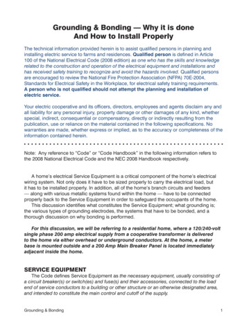
SE-330 Neutral-Grounding-Resistor MonitorPage 6Rev. 11-A-0630182.6 Relay K1 LEDThe yellow RELAY K1 LED follows the state of relay K1 and is onwhen K1 is energized (contact closed).2.7 Unit Healthy OutputThe UNIT HEALTHY relay K4 provides a basic status of processorhealth, which is energized when the processor is operating. It canbe ordered with N.O. or N.C. contacts. See section 7.An ENHANCED HEALTH status can be assigned to relays K1, K2,and K3. See Section 2.9.UNIT HEALTHY relay K4 is energized when the processor isoperating. It can be ordered with N.O. or N.C. contacts. See Section 7.NOTE: The K4 output changes state momentarily during aprocessor reset.FIG. 2. Analog-output connections.NOTE: K4-contact rating is 100 mA maximum.3. INSTALLATION2.8 Diagnostic LEDOutline and panel-cutout dimensions for the SE-330 are shownin Fig. 4. To panel mount the SE-330, insert it through the panelcutout and secure it with the four included 8-32 locknuts and flatwashers.The DIAGNOSTIC LED is used to annunciate trips withoutindividual LED indication. The number of short LED pulses betweenpauses indicates the cause of the trip.By default, only critical diagnostic flash codes are shown. Noncritical diagnostic codes include SD Card status and USB Errorstatus. All other diagnostic codes are considered critical.Starting with SE-330 firmware version 2.60 and SE-MON330software version 3.8, the SE-330 can be configured to showonly critical diagnostic codes. In this configuration, only criticaldiagnostic codes will be indicated with the DIAGNOSTIC LED.Diagnostic messages are always visible with the SE-MON330software. See Sections 4.2 and 5.2.9 Enhanced Health StatusThe Enhanced Health Status can be assigned to relays K1, K2,and K3 (firmware version 3.00 and higher). The assigned relay(s)will trip when a critical diagnostic code occurs. See Section 5 for alist of critical diagnostic codes.2.10 Analog OutputAn isolated 4–20-mA output indicates NGR current with fullscale output corresponding to the CT rating. An internal 24-VDCsupply allows the analog output to be connected as a self-poweredoutput. Power from an external supply is required for loop-poweredoperation. See Fig. 2. A PGA-0520 analog meter can be panelmounted to display the NGR current. See Fig. 19 and Se
The SE-330 provides additional features over the SE-330 legacy model (revision 04 or less): NGR short detection capability. Configurable output relay function and operating mode (K1, K2, and K3). When the trip level is set to MEM, the ground-fault trip setting is defined by an internal non-volatile memory variable. The