Transcription
16582/16418 WirelessCommunicationLecture Notes 7: Mobile RadioChannel Modeling IISt ti ti l MStatisticalModelsd l ffor FFadingdiProcessesDr. Jay Weitzen
Contents Quick Review of Fading Models Statistical Models for Channel Fading Process– Rayleigh– Rician– Nakagami CCalculatingl l ti FFaded DDurations,tiRRates,tanddDDepthsth Case Study: Characterizing the MMDS WirelessChannel CombatingC b i lizationli tiRake ReceiverOFDM Appendix: Introduction to MIMO for 4th generationc 2007-2012 Dr. Jay Weitzensystems2
Quick Review of Fading Models Dispersion in Time and Frequency EffectChannel model In TimeTime, look at relation between multipathspread and bit duration– SeSelectiveect e oor Flatat Fadingad g– BW of channel vs. BW of signal In frequency look at Doppler Spreadrelative to inverse of Bit Duration– Fast or Slow Fadingg– Signaling rate vs. channel change ratec 2007-2012 Dr. Jay Weitzen3
leFadingon Multipath Tİme Delay Spread)Flat FadingFFrequencySelectiveS l ti FadingF di1. BW Signal BW of Channel1. BW Signal Bw of Channel2. Delay Spread Symbol Period2. Delayy Spreadp SymbolyPeriodSmall-scale Fading(Based on Doppler Spread)Fast FadingSlow Fading1. Low Doppler Spread1 High Doppler Spread1.2. Coherence Time Symbol Pe2. Coherence Time Symbol Period3. Channel variations smaller tha3. Channel variations faster than basebandsignalgvariationssignal variationsc 2007-2012 Dr. Jay Weitzen4
Impulse Response of the FadingM lti th ModelMultipathM d lc 2007-2012 Dr. Jay Weitzen5
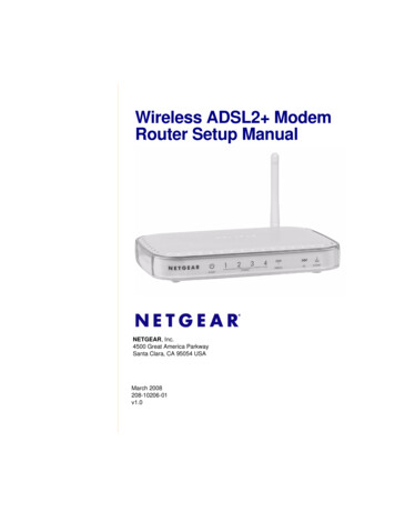
Flat Fading Occurs when symbol period of thetransmitted signal is much larger than theDelay Spread of the channel– Bandwidth of the applied signal is narrow. Occurs when the amplitude of the receivedsignal changes with time For example according to Rayleigh Distribution May cause deep fades.– Increase the transmit power to combat this situation.situationc 2007-2012 Dr. Jay Weitzen6
Flat Fadings(t)h(t, r(t) TS0TSOccurs when:BS BCandTS 0 0TS BC: Coherence bandwidthBS: Signal bandwidthyperiodpTS: Symbol : Delay Spreadc 2007-2012 Dr. Jay Weitzen7
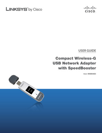
Frequency Selective Fading Occurs when channel multipath delayspread is greater than the symbol period.– Symbols face time dispersion– Channel induces Intersymbol Interference(ISI) Bandwidth of the signal s(t) is wider thanthe channel impulse responseresponse.c 2007-2012 Dr. Jay Weitzen8
Frequency Selective Fadings(t)r(t)h(t, TS0 TS0 0 TSTS Causes distortion of the received baseband signalCauses Inter-Symbol Interference (ISI)Occurs when:BS BCandTS As a rule of thumb: TS c 2007-2012 Dr. Jay Weitzen9
ISIS iss resultesu t ofo SelectiveSe ect e Fadingad gc 2007-2012 Dr. Jay Weitzen10
Fast Fading Due to Doppler Spread Rate of change of the channel characteristicsis larger than theRate of change of the transmitted signal The channel changes during a symbol period. The channel changes because of receiver motion. Coherence time of the channel is smaller than thesymbolyperiodpof the transmitter signalgOccurs when:BS BDandTS TCBS: Bandwidth of the signalgBD: Doppler SpreadTS: Symbol PeriodTC: Coherence Bandwidthc 2007-2012 Dr. Jay Weitzen11
Slow Fading Due to Doppler Spread Rate of change of the channel characteristicsis much smaller than theRate of change of the transmitted signalOccurs when:BS BDandTS TCBS: BandwidthB d idth off ththe signalilBD: Doppler SpreadTS: Symbol PeriodTC: Coherence Bandwidthc 2007-2012 Dr. Jay Weitzen12
DifferentTypesofFadingTSFlat FastFadingFlat SlowFadingSymbol Period ofTransmitting Signal Frequency SelectiveFast FadingFrequency SelectiveSlow FadingTCTSTransmitted Symbol PeriodWith Respect To SYMBOLSO PERIODOc 2007-2012 Dr. Jay Weitzen13
Different Types of FadingBSFrequency SelectiveFast FadingFrequency SelectiveSlow FadingTransmittedBBasebandb dBCSignal BandwidthFlat FastFadingFlat SlowFadingBDBSTransmitted Baseband Signal BandwidthWith Respect To BASEBAND SIGNAL BANDWIDTHc 2007-2012 Dr. Jay Weitzen14
Statistical Models For SmallScale Fading
Three Major Effects: Attenuation, Long-term Fading(Shadowing), and Short-term Fading.Buildings,BildiTrees, carsobstruct signalson a medium tosmall scale:ShadowingFading occurswith distance onorder of ¼wavelengthAttenuation:SignalgAttenuates withDistancec 2007-2012 Dr. Jay Weitzen16
Fading Is the Result of Constructive andD tDestructivetiWaveWCombiningCbi ic 2007-2012 Dr. Jay Weitzen17
SmallSa ScaScalee Fadingad g in Space anda d Timeec 2007-2012 Dr. Jay Weitzen18
Space/TimeSpace/e Interferencete e e ce patternspatte sc 2007-2012 Dr. Jay Weitzen19
Impulse Response of a MultipathChChannellAican be deterministic or random complexpGaussian Variablesc 2007-2012 Dr. Jay Weitzen20
Many Scatterers from same distanceresults in random fading at eachdistance binc 2007-2012 Dr. Jay Weitzen21
Manya y Wavesa es CombineCo b e Dueue to ScatteringScatte gc 2007-2012 Dr. Jay Weitzen22
Real and Imaginary Parts are GaussianDDuetot CentralC t l LimitLi it TheoremThc 2007-2012 Dr. Jay Weitzen23
Fading Distributions Describes how the received signal amplitudechanges with time.– Remember that the received signal is combination of multiplesignals arriving from different directionsdirections, phases and amplitudesamplitudes.– With the received signal we mean the baseband signal, namelythe envelope of the received signal (i.e. r(t)). Its is a statistical characterization of themultipath fading. Often used distributions– Rayleigh Fading– Ricean Fading– Nakagami Fadingc 2007-2012 Dr. Jay Weitzen24
Rayleigh and RicianDi t ib tiDistributions Rayleigh Describes the received signal envelopedistribution for channels, where all thecomponentspare non-LOS: i.e. there is no line-of–sight (LOS)component. Rician Describes the received signal envelopedistribution for channels where one of themultipath components is LOS component. i.e. there is one LOS component.c 2007-2012 Dr. Jay Weitzen25
Rayleigh Fadingc 2007-2012 Dr. Jay Weitzen26
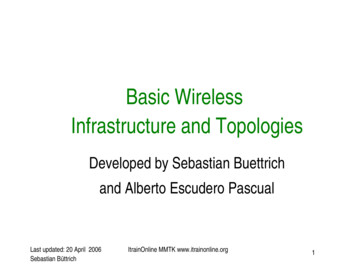
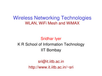
Rayleigh FadingRayleigh distribution has the probability density function (PDF) given by: r2 2 2 r e p(r) 2 0(0 r )(r 0) 2 is the time average power of the received signal before envelope detection. is the rms value of the received voltageg signalgbefore envelopep detectionRemember:2P (average power) Vrms(see end of slides 5)c 2007-2012 Dr. Jay Weitzen27
Rayleigh Fading (cont(cont’d)d)The probability that the envelope of the received signal does not exceed aspecified value of R is given by the CDF:R P(R) Pr (r R) p(r)dr 1 eR22 20 rmean E[r ] rp (r )dr 0rmedian 2 1.2533 1 1.177 found by solving 2rmedian p(r )dr0rrms 2 c 2007-2012 Dr. Jay Weitzen28
Rayleigh PDF0.7 0.6mean 1.2533 median 1.177 variance 0.4292 0.50.40.30.2010.100 12 3 4 5 c 2007-2012 Dr. Jay Weitzen29
Pdfd aandd CdCdf ofo Rayleighay e g Fadingad gc 2007-2012 Dr. Jay Weitzen30
Thee Envelopee ope iss Rayleighay e g Distributedst butedc 2007-2012 Dr. Jay Weitzen31
Rayleighay e g Fadingad g Margina gc 2007-2012 Dr. Jay Weitzen32
Rayleighay e g Outage Probabilityobab tyRayleigh FadingOutage argin (dB)c 2007-2012 Dr. Jay Weitzen33
Digital Communication in RayleighF diFadingiis DiffiDifficultltc 2007-2012 Dr. Jay Weitzen34
Ricean Distribution When there is a stationary (non-fading)LOS signal present, then the envelopedistribution is RiceanRicean. The Ricean distribution degenerates toRayleigh when the dominant componentfades away.c 2007-2012 Dr. Jay Weitzen35
Ricianc a PDFc 2007-2012 Dr. Jay Weitzen36
Ricianc a Fadingad gc 2007-2012 Dr. Jay Weitzen37
Nakagamia agaProbabilityobab ty Distributionst but oc 2007-2012 Dr. Jay Weitzen38
Nakagami Shape Factorc 2007-2012 Dr. Jay Weitzen39
Nakagami Fading for stationaryuserc 2007-2012 Dr. Jay Weitzen40
Level Crossing and Fade Ratesc 2007-2012 Dr. Jay Weitzen41
Level Crossing Rate (LCR)Threshold (R)( )LCR is defined as the expected rate at which the Rayleigh fadingenvelope, normalized to the local rms signal level, crosses a specifiedthreshold level R in a positive going direction. It is given by:N R 2 f m e 2where R / rrms(specfied envelope value normalized to rms)N R : crossings per secondc 2007-2012 Dr. Jay Weitzen42
Average Fade DurationDefined as the average period of time for which the received signal isbelow a specified level RR.For Rayleigh distributed fading signal, it is given by: 11 2 Pr[r R] 1 eNRNR 2e 1R , rrms fm 2 c 2007-2012 Dr. Jay Weitzen43
ADF for Different Distributionsc 2007-2012 Dr. Jay Weitzen44
Fading Model –Gilbert Elliot ModelGilbert-ElliotFade PeriodSignalgAmplitudeThresholdTime tGoodBad(Non-fade)(Fade)c 2007-2012 Dr. Jay Weitzen45
Gilbert-Elliot Model1/AFDG dGoodB dBad(Non-fade)(Fade)1/ANFDThe channel is modeled as a Two-State Markov Chain.Each state duration is memory-less and exponentially distributed.The rate going from Good to Bad state is: 1/AFD (AFD: Avg Fade Duration)The rate going from Bad to Good state is: 1/ANFD (ANFD: Avg Non-FadeDuration))c 2007-2012 Dr. Jay Weitzen46
16.58216582 CCase StStudy:dChannel Measurements for2G MMDS and applicability to4G LTE and WiMax
Credits Based on slides fromfrom, Dhananjay GoreGore,Stanford University Conducted for Sprint BroadbandBroadband, 199919992000c 2007-2012 Dr. Jay Weitzen48
Goal of ProgramTo characterize wireless channelsfor 2G MMDS but 4G has beendeployed in this bandBTSChannelCPEc 2007-2012 Dr. Jay Weitzen49
What Is MMDS? MMDS (Microwave Multipoint distributionSystem), is a band of frequencies at 2.5 GHz,allocated for fixed and mobile digitalcommunicationi ti– Originally viewed as a “wireless cable” system forgservicesbroadcast digital– Viewed as mostly TDD Business case required self installable CPEantennastandd needd tto kknow reliabilityli bilit anddchannel characteristicsc 2007-2012 Dr. Jay Weitzen50
Typical ScenarioCo-Channel BTSBTS50’-100’Ht 8’-15’0.1 - 4 milesDistance tomobilescatterersc 2007-2012 Dr. Jay Weitzen51
Scenario Dimensions Terrain– Rural, Suburban, Urban, Hilly Antenna Configuration– BTS, CPE antenna heights & spacing– Polarization,, Beam-width Reuse Factor– 1 and 3 Sectorization–3c 2007-2012 Dr. Jay Weitzen52
Antenna Configurations BTS antenna heights– 35’, 50’, 80’,120’ (35-120 ft) CPE antenna heights– Under the eaves: 85” to 95”, ( 7 ft)– Patio of a Condominium: 130” ( 10 ft)– Rooftop: 175”175 to 220”220 (15-20(15 20 ft) CPE antenna spacing– 0.50 5 - 5 wavelengths Beam-width 900 at BTS and 500 at CPEc 2007-2012 Dr. Jay Weitzen53
Measurement SetSet-upupAnt 1Ant 1DualPAcustom2 x HP 4433BNI PCI-MIO-16E-1Ant 1Ant 1customHi LOSignalSignalGeneratorGeneratorHP 4433BHP 8648CRubidiumClockRubidiumClockDAQ Card2 x IQC Lo LOSignalSignalGeneratorGenerator10MHz / 1PPSDividerCircuitDual RxPreprocessingADClockMatlabDataAnalysis10MHz / 1PPSDividerCircuitPCBTSCCICPE2480 MHz4 MHz BWc 2007-2012 Dr. Jay Weitzen54
Measured Channel Parameters Path LossK-factorDelay SpreadDoppler Power SpectrumLevel Crossing Rates (LCR)Averageg Duration of Fade ((ADF))Antenna CorrelationC/I ratiosc 2007-2012 Dr. Jay Weitzen55
Path-LossPathLoss Measurements Published literature (AT&T measurements) SU measurements only for 0.1-4 miles SU measurements made in multiple Bayarea locations SUS measurements agree with AT&T&measurementsSU: Stanford Universityc 2007-2012 Dr. Jay Weitzen56
G2 MMDS Path Loss ModelMedian Path Loss:PL(dB) A 10 log10 (d / d0 ) s PL f PLhfor d d0whereA 20 logl 10 ( 4 d 0 / )(free space path loss) a bhb c h , 10 meters h b b 80 meters(mean path loss exponent) is the wavelengthc 2007-2012 Dr. Jay Weitzen57
Path Loss Model (contd.) s is a lognormal shadow fading– zero mean– terrain dependent standard deviation hb is the BTS height in meters a, b, c are constants dependent on theterrain category d o is chosen as 100m (reference distance) d is the distance from BTSc 2007-2012 Dr. Jay Weitzen58
Correction Terms Frequency correction terms PL f 5.7 log f 2000 f in MHz CPE height correction term ( 2 meters) PLh 10.8 log(g(hCPE2) 1 meter hCPE 8 metersc 2007-2012 Dr. Jay Weitzen59
Path Loss Scatter Plot-60-80- Pathh Loss [dB]-100SU Measurementseasu e e s-120*From Erceg Model-140-160-180180-200-110010Base-Terminal Distance ((km))110c 2007-2012 Dr. Jay Weitzen60
Mean Path Loss vs Distance-80Super CellMean Path-Loss minal Distance (km)110c 2007-2012 Dr. Jay Weitzen61
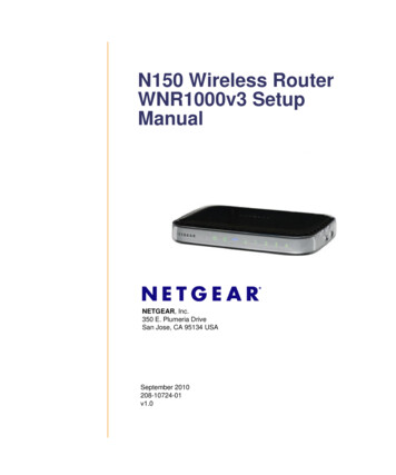
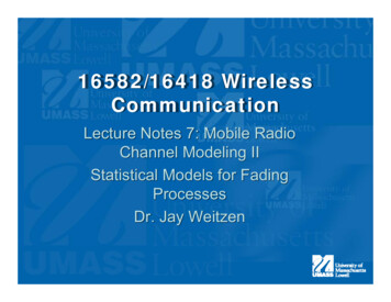
K-factor Measurementspower in fixed (mean) componentK power ini varyingi (scattered( tt d) componenttTypical Signal Envelope:K 6 dB-75-75-80-80RSL(dB)RSL(dB)K -1010 dB-85-90-95-1000-85-90-9520406080100120Time Time ((sec))c 2007-2012 Dr. Jay Weitzen62
K-factorKfactor Model Erceg model for K-factorK Fs Fh Fb K o d u Fs is a seasonal factor– 1.0; summer (leaves)– 2.5; winter (no leaves) Fh is the heightg factor– (h/3)0.46 (h is the CPE height in meters)c 2007-2012 Dr. Jay Weitzen63
K-factorKfactor Model (contd.) Fb is the beamwidth factor– Fb (b/10)-0.62; (b in degrees) Ko andd are regressioni coefficientsffi i t– Ko 10; -0.5 u is a lognormal variable– zero mean– std. deviation of 8.0 dBc 2007-2012 Dr. Jay Weitzen64
K-factorKfactor Scatter Plotht 15m, 90 deg. Rx antenna4030K--Factor in dBSU Measurements20From Erceg Model100hr 3m-1099.9% reliability-20-110010110Distance in kmc 2007-2012 Dr. Jay Weitzen65
K-factorKfactor and Reliability K-factors are highly variable To ensure 99.9% reliability, systemsmust be designed for zero K-factor(Rayleigh fading)c 2007-2012 Dr. Jay Weitzen66
Delay Spread Model SpikeSpike-Plus-ExponentialPlus Exponential Model (Erceg) P A ( ) B e i / o ( i )i 0A, B, o and are experimentallydetermined Trms / 2 oe e / 2 o Good Model for directive antennasc 2007-2012 Dr. Jay Weitzen67
Delay Spread Scatter PlotRMS Delay SSpread in Microoseconds (dB)(Suburban)105SU Measurements0-5From Erceg Model-1010-15-20-25 -110010110Distance in kmc 2007-2012 Dr. Jay Weitzen68
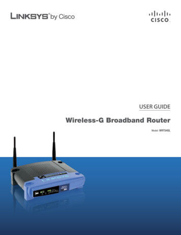
-122122-126126-124-128-126-130dbdbDoppler Power Spectrum-128-134-130fD 0.4Hz-132-134-0.5-132-0.4-0.3-0.2-0.10fD(Hz)0.1Low WindfD 1.522.5High WindRounded Spectrum with fD 0.1Hz- 2Hzc 2007-2012 Dr. Jay Weitzen69
Level Crossing Rate (LCR)LCR is the rate ((in sec)) at which the signalgcrossesa certain levelSiggnal LevelLevelLevel CrossingsgTimec 2007-2012 Dr. Jay Weitzen70
LCR (measured)LCR vs BTS antenna height for "UNDER THE EAVES" CPE10LCR (per sec)101010-1bts 35ft1010bts 50ft-2bts 80ft-3-14-12-10-8-6-4-20246level (dB) w.r.t. mean powerc 2007-2012 Dr. Jay Weitzen71
Average Duration of Fade(ADF)ADF iis ththe average ddurationti (i(in secs)) ffor whichhi h ththe signalil llevellstays below a certain thresholdt1t2t3t4t5Siggnal LevelLevelADF ti ))/NN: No. of fades0TimeTc 2007-2012 Dr. Jay Weitzen72
ADF (measured)ADF vs BTS antenna height for "UNDER THE EAVES" CPE10ADF (sec)1010101010103210-1-2bts 35ftbts 50ftbts 80ft-3-14-12-10-8-6-4-20246level (dB) w.r.t. mean powerc 2007-2012 Dr. Jay Weitzen73
Antenna Correlation (Spatial)s1(t)s2(t) s ,s 12E[ s1s 2 ] - E[ s1 ]E[ s 2 ]E[( s1 E[ s1 ]) 2 ]E[( s 2 E[ s 2 ]) 2 ]c 2007-2012 Dr. Jay Weitzen74
CPE Antenna CorrelationCoefficient vs Antenna SpacingCoorrelation coefficient0.8BTS ht 3535’0.70.6CPE (V. Pol)050.5CPE ht 97"0.40.511.522.533.544.55Antenna separation (wavelengths) 0.75 - 1 wavelength spacing adequate for under the eaves CPEgsufficient for BTS antenna spacingpg 10 wavelengthsc 2007-2012 Dr. Jay Weitzen75
Frequency 161727284816127248718374827489565132395Second Tier53919532395First Tier53932956172BTS (1)139569372568392753129543798213693232Reuse Factor 3 x 9c 2007-2012 Dr. Jay Weitzen76
Measured C/I (Cell Edge)Excellent ConditionsElectioneer RdReuse 3Rx Ant 1Path LLoss [-dB]-120PrimaryC/I: 29.6447 dB-140C/I 29.6dB-160-180PrimaryCCICCI204060Electioneer Rd80Time (s)Reuse 3100120140160Rx Ant 2Path Loss [-dB]-120120PrimaryC/I: 33.8216 dB-140C/I se 3c 2007-2012 Dr. Jay Weitzen77
Measured C/I (Cell Edge)Poor ConditionsWelch RdReuse 3Rx Ant 1Path LLoss [-dB]-120PrimaryC/I: 8.3504 dBC/I 8.3 dB-140-160-180PrimaryCCICCI2040Welch Rd6080Time (s)Reuse 3100120140Rx Ant 2Path Loss [-dB]-120120PrimaryC/I: 0.21909 dB-140C/I 0.21 dB-160-180PrimaryCCICCI20406080Reuse 3100120140c 2007-2012 Dr. Jay Weitzen78
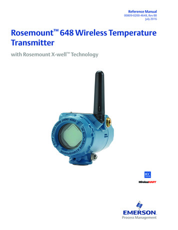
CDF of C/ I at the Cell Edge(Reuse 3 x 9)1 C/I statisticsCDF at thhe Cell Edge0.8- Randomly populate subs0.6- Compute path loss andshadow loss0.4- Compute C/I- Average over many trials0.280 % coverage for cell edge0-10010203040C/I (dB)c 2007-2012 Dr. Jay Weitzen79
Summaryy Over 200 hrs of measurement effort MeasuredMd parameterst(Path(P th LLoss, KK-factorf tand Delay Spread) appear to conform toAT&T results Consistency in new measurements ofDoppler antenna correlationDoppler,correlation, LCR and ADF We feel reasonably comfortable thatmeasurements capture the true nature ofMMDS propagation More measurements plannedc 2007-2012 Dr. Jay Weitzen80
References V. Erceg et. al, “An empirically based path loss model for wirelesschannels in suburban environments,” IEEE JSAC, vol. 17, no. 7, July1999, pp. 1205-1211. V.V Erceg et.al,et al “AA model for the multipath delay profile of fixed wirelesschannels,” IEEE JSAC, vol. 17, no.3, March 1999, pp. 399-410. Larry J. Greenstein et.al, “A new path-gain/Delay-spread propagationModel for digital Cellular Channels,” IEEE Trans. On VehicularTechnology vol.Technology,vol 4646, nono. 22, May 19971997. L.J. Greenstein, S. Ghassemzadeh, V.Erceg, and D.G. Michelson,“Ricean K-factors in narrowband fixed wireless channels: Theory,experiments, and statistical models,” Proceedings of WPMC’99,Amsterdam, September 1999. David Parsons, “The Mobile Radio Propagation Channel,” John Wileyand Sons, 1992. L. J. Greenstein and Vinko Erceg, “Gain Reductions Due to Scatter onWireless Paths with Directional AntennasAntennas,” IEEE CommunicationsLetters, vol. 3, No. 6, June 1999. L.J. Greenstein et.al, “Moment-method estimation of the Ricean Kfactor,” IEEE Communications Letters, vol.3, no.6, June 1999, pp.175-176.c 2007-2012 Dr. Jay Weitzen81
Diversity in Mobile RadioSystems
Space Time Fading: Wide Beamc 2007-2012 Dr. Jay Weitzen83
Space time Fading, narrowbeamc 2007-2012 Dr. Jay Weitzen84
Independent Paths.4 Space Diversity– Multiple antenna elements separated bydecorrelation distancedistance. Polarization Diversity– Two transmit or receive antennas with differentpolarizationsBc Frequency Diversityf– Multiple narrowband channels separated by channelcoherence bandwidthT Time Diversityctc 2007-2012 Dr. Jay Weitzen– Multiple timeslots separated by channelcoherencetime.85
Introduction to Diversity Basic Idea– Send same bits over independent fadingpaths– Combine paths to mitigate fadingeffectsTbMultiple paths unlikely to fade simultaneouslytc 2007-2012 Dr. Jay Weitzen86
How To Maximize Diversity Want 2 or more signals withapproximately same average power Want signalsgto be uncorrelatedc 2007-2012 Dr. Jay Weitzen87
Combining Techniques Selection Combining– Fading path with highest gain used Equal Gain Combining– All ppaths cophasedpand summed with equalqweighting MaximalM i lRRatioti CCombiningbi i– All paths cophased and summed with optimalweightingi hti tto maximizei i combinerbioutputt t SNRc 2007-2012 Dr. Jay Weitzen88
Maximum ratio combining(MRC)h1*h1 xyh2h2*c 2007-2012 Dr. Jay Weitzen89
Maximumau ratioat o combiningco bg (cont’d)(co t d)c 2007-2012 Dr. Jay Weitzen90
Selection combining (SC)MonitorSNRSelectbranchh1yxh2c 2007-2012 Dr. Jay Weitzen91
Switched diversity Switched diversity– Switch-and-stay combining (SSC)Channel– Switch-and-examine combining (SEC)estimatorComparatorswitchingthresholdh1xh2c 2007-2012 Dr. Jay Weitzen92
CalculatingCacu at g Probabilityobab ty ofo ErroroIntroduction Improvements related to a reduced fading level arecommonly quantified by average error rate curves. TheTh average error ratet may ini some cases bebdifficult to evaluate analytically.Motivation Quantify the severity of fading by using a measuredirectly related to the fading distribution.distributionc 2007-2012 Dr. Jay Weitzen93
Diversity Performance MaximalM i lRRatioti CCombiningbi i (MRC)––––Optimal technique (maximizes output SNR)Combiner SNR is the sum of the branch SNRsSNRs.Distribution of SNR hard to obtain.Exhibits 10-40 dB gains in Rayleigh fading. Selection Combining (SC)––––Combiner SNR is the maximum of the branch SNRs.Diminishing returns with # of antennas.CDF easy to obtain, pdf found by differentiating.Can get up to about 20 dB of gain.c 2007-2012 Dr. Jay Weitzen94
Multiuser diversity GainSystem throughput for N users than for 1 user1Spatial diversitySCSEC2KUser 1Multiuser diversityUser 2 Combiner Base stationAntennas Individual users AntennasUser Kc 2007-2012 Dr. Jay Weitzen95
Multi-Useru t Use Diversitye s ty (co(cont’d)t d)Introduction Always searching for the best user results ina high and determinstic feedback load.Motivation Utilize switched diversity algorithms reportedin the literature as multiuser access schemesto reduce the average feedback load. The base station probes the users in asequential manner, looking not for the bestuser butb t forf an acceptablet bl user.c 2007-2012 Dr. Jay Weitzen96
Combating Rayleigh Fading:SSpaceDiDiversityitD Signal receivedby Antenna 1Signall receivedSii dby Antenna 2 Fortunately, Rayleigh fades arevery short and last a smallpercentage of the timeTwo antennas separated byseveral wavelengths will notgenerally experience fades at thesame time“Space Diversity” can be obtainedby using two receiving antennasandd switchingit hi iinstant-by-instantt t b i t t totwhichever is bestRequired separation D for gooddecorrelation is 10-20 – 12-24 ft. @ 800 MHz.– 5-10 ft. @ 1900 MHz.CombinedSignalc 2007-2012 Dr. Jay Weitzen97
Space Diversity ApplicationLimitationsDSignal receivedby Antenna 1Signall receivedSii dby Antenna 2CombinedSignal Space Diversity can be applied onlyon theth receivingi i endd off a link.li k Transmitting on two antennaswould:– fail to produce diversitydiversity, sincethe two signals combine toproduce only one value ofsignalglevel at a ggiven ppoint -no diversity results.– produce objectionable nulls inthe radiation at some angles Therefore, space diversity isapplied only on the “uplink”, i.e.,reverse path– there isn’tisn t room for twosufficientlyseparatedantennasc 2007-2012Dr. Jay Weitzenon a mobile or handheld98
Polarization DiversityWhere SpacepDiversityy Isn’t Convenient V Hor\ / A BA BAntenna AAntenna BCombinedSometimes zoning considerations oraesthetics preclude using separatediversity receive antennasDual-polarized antenna pairs within asingle radome are becoming popular– Environmental clutter scatters RFenergy into all possible polarizations– Differently polarized antennas receivesignals which fade independently– In urban environmentsenvironments, this is almost asgood as separate space diversityAntenna pair within one radome can be VH polarized, or diagonally polarized– Each individual array has its ownindependent feedline– Feedlines connected to BTS diversityinputs in the conventional way; TXduplexing OKc 2007-2012 Dr. Jay Weitzen99
The Reciprocity PrincipleDoes it apply to Wireless?-148.21 db@ 870.03 MHz-148.21 db@ 870.03 MHz-151.86151 86 db@ 835.03 MHzBetween two antennas, on the sameexact frequency, path loss is thesame ini bothb th directionsditi But things aren’t exactly the same incellular -– transmit and receive 45 MHz.apart– antenna: gain/frequency slope?– different Rayleigh fadesup/downlink– often, different TX & RX antennas– RX diversity Notice also the noise/interferenceenvironment may be substantiallydifferent at the two ends So, reciprocity holds only in a generalsense for cellularc 2007-2012 Dr. Jay Weitzen100
Frequency Diversityc 2007-2012 Dr. Jay Weitzen101
c 2007-2012 Dr. Jay Weitzen102
Frequency Hopping for Diversityc 2007-2012 Dr. Jay Weitzen103
Frequency Hopping and C/Ic 2007-2012 Dr. Jay Weitzen104
Receive DiversityPerformanceDiversitygainc 2007-2012 Dr. Jay Weitzen105
Interleaving and Deinterleaving for FadingChannels
Motivation for Interleaver Interleaving is a form of time diversity– Usually combined with coding to provideprotection against burst errors caused byfading Viterbi Algorithm used for detection ofconvolutional codes is not effective againstburst errorserrors. We add interleaver todistribute burst error.c 2007-2012 Dr. Jay Weitzen107
Forward Error Correction for Fading Channelsc 2007-2012 Dr. Jay Weitzen108
Theory of Interleavingc 2007-2012 Dr. Jay Weitzen109
Error Performance on Fading Channelsc 2007-2012 Dr. Jay Weitzen110
Block InterleaverOriginal 11000011Interleaver00101011001001111011Burst Error001101010010011110111011The order of originalMessagegg ischanged by Block Interleaver.c 2007-2012 Dr. Jay Weitzen111
Blockoc Deinterleavere e ea eReceived 001001111011Burst ErrorDeInterleaver01110001110010110011Distributed Errorc 2007-2012 Dr. Jay Weitzen112
Example: CD Interleavingc 2007-2012 Dr. Jay Weitzen113
c 2007-2012 Dr. Jay Weitzen114
Example: SatelliteCCommunicationsi tic 2007-2012 Dr. Jay Weitzen115
Performance with Interleavingc 2007-2012 Dr. Jay Weitzen116
Combating Effects of Multipathand Fading in Wireless Systems
What to do against ISI? Wideband signals:– channel delay many symbol periods– heavy distortion of the received signalsignal. Several techniques can be applied to reduce orget rid of ISI in wideband signal transmission– Equalization (2nd gen)– spread-signalspread signal modulation (3rd gen)– OFDM (4th gen)c 2007-2012 Dr. Jay Weitzen118
Equalization The received signal is filtered in such a way thatISI is eliminated or reduced.– Ideal ISI elimination is achieved when the filter is theinverse of the channel response.– Clearly, the channel must be known, or accuratelyestimated to perform effective equalization.estimated,equalization– Therefore, the equalizer needs to be trained to adapty g channel in wireless systems.yitself to the time-varyingUsually this is achieved by transmitting a trainingsequence. EEqualizationli ti off ththe signalil resultslt iin a ddecreaseof ISI at the cost of a lower signal-to-noise ratio(SNR)c 2007-2012 Dr. Jay Weitzen119
Direct sequence spreadspectrumt In DS-SS modulation, the signal is multiplied with a code thatresults in a signal with a much wider bandwidth than the originalinformation-bearing signal. In a time-dispersive multipathchannel, the spread signal replicas, which travel via differentpaths, are un-correlatedun correlated if the path delays are more than onesymbol period apart from each other. After decorrelation in thereceiver, the signal replicas from different paths are combined ina Rake receiver, thus all received energygy is effectivelyy used.A disadvantage of using DS-SS with high bit-rate signals is thatto achieve a sufficiently high processing gain, a very largebandwidth is required.qThis is especiallypy the case in an indoorenvironment, where the delay times between the paths are veryshort, in the order of 1 ns.c 2007-2012 Dr. Jay Weitzen120
OFDM Symbols of high bit rate signal are distributed over ag number of subcarriers.large– Low symbol rate per carrier.– Individual carrier signals see flat fading (no ISI). Promising techniqtechniquee for ffuturet re high bitbit-raterateapplications. However,, it suffers from a number of problems:p– a very linear amplifier in the transmitter is required to preventsignal distortion,– accurate synchronization in the receiver is neededneeded,– in the transmitter and receiver real-time discrete Fouriertransform (DFT) operations have to be computed.c 2007-2012 Dr. Jay Weitzen121
Improving Performance ofWireless Channels using MIMO(the next generation ofdiversity)
MIMO is the Next generation ofDiDiversityi SystemsS Single-input, single-output (SISO) channelNo spatial diversity Single-input,gp multiple-outputpp (SIMO) channelReceive diversity MultipleMultiple-input,input, singlesingle-outputoutput (MISO) channelTransmit diversity Multiple-input,Multiple input multiple-outputmultiple output (MIMO)channelC bi d transmitCombinedtit andd receivei diversitydiitc 2007-2012 Dr. Jay Weitzen123
Introduction to the MIMO Channelc 2007-2012 Dr. Jay Weitzen124
Capacity of MIMO Channelsc 2007-2012 Dr. Jay Weitzen125
Single Input- Single Outputsystems (SISO)x(t): transmitted signaly(t): received signalg(t): channel transfer functionn(t): noise (AWGN, 2)gy(t)x(t)y(t) g x(t) n(t)ESignal to noise ratio : ρ g 2xCapacitypy: C σlogg2(1 )( )2c 2007-2012 Dr. Jay Weitzen126
Single Input- Multiple Output (SIMOMultiplelti l Inputt Singlei l Outputt t (MISO Principle of diversity systems (transmitter/receiver) : Higher average signal to noise ratioRobustness - : Process of diminishing returnBenefit reduces in the presence ofcorrelation Maximal ratio combining Equal gain combining Selection combiningc 2007-2012 Dr. Ja
c 2007-2012 Dr. Jay Weitzen 46. 16 582 C St d16.582 Case Study: Channel Measurements for 2G MMDS and applicability to 4G LTE and WiMax. Credits Based on slides from Dhananjay GoreBased on slides from, Dhananjay Gore, Stanford University Conducted for Sprint Broadband 1999Conducted for Sprint Broadband, 1999-