Transcription
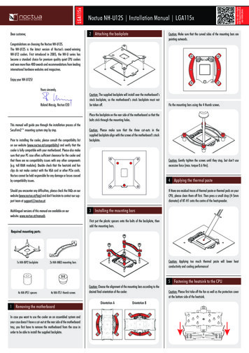
PAC-2800BTELECTRIC COOLING FAN CONTROLLERIncluded components:PAC-2800BTOptional components sold separately:- Second 70 amp relay for dual fan or two speed fan operation – RLY-3- Dakota Digital 300ºF temperature sender - 140022Installation Mount ONLY in vehicle cabin. Controller is not designed for engine compartment mounting.PAC-2800BT does NOT offer a constant temp display, but locate the module so the LED display can beseen and the built-in programming switches can be reached for initial setup, future adjustments andtroubleshooting.Settings for several aftermarket temperature gauges are included to make installation easier: StewartWarner, Classic Instruments, VDO, and Autometer. If your gauge isn’t listed, a custom calibrationoption allows the PAC-2800BT to be calibrated to almost any gauge with clear numerical tempmarkings. The engine temperature can also be read directly from an OBDII diagnostic port with the useof a Dakota Digital BIM-01-X unit.1MAN# 650700:A
Wiring overviewPAC-2800 terminal strip connections: FAN HIGHGround-trigger output; connect to the high fan relay harness white wire.(for single fan applications leave unconnected)FAN LOWGround-trigger output; connect to the low fan relay harness white wire.SENDERTemperature sender input, connect to the engine temperature sender wire.A/C 12V trigger from AC compressor cycle switch.(on systems without air conditioning leave unconnected)DISABLEGround trigger input to disable fans. This ignores the temperature input and keeps the fans off.(normally left unconnected)IGNITIONSwitched 12V input for PAC-2800; key-on hot (ignition power) only. Use a quality 5A fuse.BATTERY Constant 12V input for PAC-2800. Use a quality 5A fuse.GROUNDGround input for PAC-2800; connect to a good chassis ground.IGNITION, GROUND & SENDER will NOT need to be wired if the three wire BIM cable is usedo Ignition, ground & data will be fed from the HDX/RTX/VHX/VFD control boxRLY-3 relay wiringWhiteGreenRedBlackGround-trigger input; connect to PAC-2800 outputRelay input for fan power supply; fused, constant 12V battery input capable of supporting cooling fan ANDis SEPARATE from the PAC-2800 12V inputsConstant relay power, can share fused 12V battery connection with PAC-2800Relay output fan power supply; connect to cooling fan2MAN# 650700:A
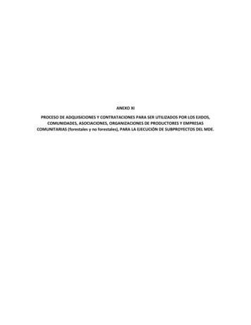
Basic Wiring with Stand Alone Sender or Gauge3MAN# 650700:A
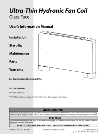
Basic Wiring with Autometer Full Sweep Water Temp Gauge4MAN# 650700:A
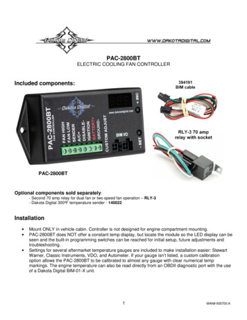
Wiring Relay for a Single Fan5MAN# 650700:A
Wiring Relays for Two Fans6MAN# 650700:A
Wiring Relays for a Dual Speed Fan7MAN# 650700:A
OperationThis electric cooling fan controller provides a way to run up to two electric engine cooling fans or one two speed coolingfan. (A second relay, sold separately, is required for two speed or dual fan operation). The controller monitors the enginetemperature using a dedicated sender, a gauge and its sender, or directly from a Dakota Digital BIM connection.When the engine temperature goes above the user-adjustable set point, the fan is turned on with a relay. When theengine has cooled below the user-adjustable off-temperature, the fan is shut off. Separate on and off temperatures can beset for the high and low fan outputs.The controller will also run the fan when the air conditioner requires, by detecting when the air conditioning clutch isengaged. When the temperature information is provided by a Dakota Digital BIM connection, a high speed shut-off is alsoavailable to disable the fans from turning on once the vehicle is above a user-adjustable speed.The unit can be set to keep the fan running (if the engine is hot enough) after the key is turned off. Several delay times areavailable from no delay to five minutes. The display will countdown the seconds left before the fan is turned off. If thebattery voltage drops too low, the fan will be turned off and a “Lo bAt” message will display for the remainder of the time.* WARNING *As a fail-safe, the fan will turn on and run continuously if the sender is disconnected. Always keep clearof the fan unless the battery is disconnected. When entering setup mode in a VHX or VFD3 instrument systemwith the PAC-2800 connected via BIM cable, the fan will begin running continuously after a two-minute delay.-IMPORTANT INSTALLATION NOTES If pairing this unit with a gauge, always ensure that your gauge is working properly. If the gauge is not readingcorrectly, the fan control unit will not have correct temperature information and cannot be guaranteed to properlycontrol the fan, possibly leading to overheating and engine damage.If a gauge is not used, ONLY a Dakota Digital 300ºF sender should be used (Dakota Digital part SEN-04-1, SEN04-2, SEN-04-4, SEN-04-5, SEN-04-6, SEN-04-7, or SEN-04-8). Other senders may not give a correct reading tothe control unit.Custom gauge calibration requires numerical marks, stock “C-NORMAL-H” type gauges cannot be accuratelycalibrated to.Factory PresetsThis controller comes preset to use a dedicated sender as follows:Dakota Digital Sender only (no gauge, see note above for 300ºF sender options)One single speed fan (FAN LOW only)205ºF on temperature200ºF off temperature30 second key-off run time (delay)If the factory settings don’t fit your application, follow the setup procedure on page 10.At anytime during the setup procedure, the key may be turned off and the settings up to that point will be saved.8MAN# 650700:A
Setup menu overview*To simplify the setup procedure, please download out IOS or Android app ‘Dakota Digital Accessory’*Setup is entered by holding the SET switch while turning the key on. The INC switch is used to change selections and theSET switch is used to save or select.Main MenuF-CFANSub MenuDescriptionselect temperature and speed units1one single speed fan2two fansspddual speed fanoN or L-Nlow speed on temperature (150F-250F) (on 1 fan)oFF or L-Flow speed off temperature (oFF 1 fan)H-N (only 2 fan or dual speed)high speed on temperatureH-F (only 2 fan or dual speed)high speed off temperatureDIS (only available if “bus” is selected as sender type)OFF, 31-74 MPHvehicle speed to disable fansDLY OFF,0.5,0.7,1.0,2.0,3.0,5.0fan delay after key off time in minutesSNDNono gauge, dedicated Dakota Digital sender onlydd1Dakota Digital individual gauge with senderdd2Dakota Digital instrument system with control boxSTEStewart Warner gauge and senderCLSClassic Instruments gauge and senderVDOVDO gauge and senderATOAutometer gauge and senderATSAutometer gauge and sender (wide sweep 5V sender)BUS ATOBIM connection with automatic selection of bus operationSL1BIM to RTX, HDX, VHX, VFD3 (SE47 &up), VFD3X (SE56 &up)SL2BIM to VFD3 (SE46 or earlier), VFD3X (SE55 or earlier)PACPAC-2800 is master connected to BIM-01-X onlyCUSCustom calibrated gaugeCAL ADJSet 4 – 6 temperature points for custom setupTSTINuse pot to raise temperature reading and turn on fansOUT OFFfans offON or LOON for single fan on, LO for 2 fan or dual speedHIhigh speed for 2 fan or dual speedBLU4 digit ID codeINC scroll the Bluetooth ID across the displaySETselect to allow changes only while in setupALLselect to allow anytimeBACsaves and exits Bluetooth menuVERshow software revision for tech support assistancerstreset PAC-2800 to factory default valuesENDexit setup9MAN# 650700:A
SetupTo enter setup mode, press and hold the SET switch, then turn the key on. The display will show “SEt”.Release the SET switch, the display will show “F-C”, as the first item in the menu list.Tapping the INC switch will step through the menu list to the desired menu item you may need to alter.Tapping the SET switch will enter the menu option displayed.Once done with that menu option, saving by tapping the SET will move you onto the next menu item in the list.Temperature unit1. Tap the SET switch. The display will show the current unit, F for F & MPH and C for C & km/h.2. Tap the INC switch to change the selection. Tap the SET switch to save it.Fan type1. Tap the INC switch until “FAN” is displayed.2. Tap the SET switch. The display will show the current setting:either1, 2, or SPD.a. 1 is for a single fanb. 2 is for two fansc. SPD is for a dual speed fani. If the dual speed fan requires two powers at the same time for high speed, select 23. Tap the INC switch to change the selection. Tap the SET switch to save it.Fan on and fan off temperatures1. Tap the INC switch until the desired setting is displayedDisplay 1 fan Display (2/SPD)OptiononL-Nfan low speed on / 5 F steps (150F-250F)offL-Ffan low speed off / 1 F steps (30F-2F below low on)H-Nfan high speed on / 2 F steps (2F above low on – 250F)H-Ffan high speed off / 1 F steps (30F-2F below high on)2. Tap the SET switch. The display will show the current temperature setting.3. Tap the INC switch to increase the temperature.4. Tap the SET- switch to decrease the temperature5. Press and HOLD either switch until “- “ to save the temp setting.6. The display show the next temp option until all temp options are seta. One may skip past part of the temp settings by tapping the INC switchDriving speed fan disable (only available with a BIM connection)1. Tap the INC switch until “DIS” is displayed.2. Tap the SET switch. The display will show “OFF" or the current speed setting.OFF, 31-74 MPH3. Tap the INC switch to change the setting. Tap the SET switch to save it.Fan remains running time after the key is turned offThis will set a time for the fan to run for a selected time after the ignition is turned off1. Tap the INC switch until “DLY” is displayed.2. Tap the SET switch. The display will show OFF or the current delay in minutes.DisplayOptionOFFFan will turn off when the key is turned off.0.530 seconds0.745 seconds1.01 minute2.02 minutes3.03 minutes5.05 minutes3. Tap the INC switch to change the setting. Tap the SET switch to save it.10MAN# 650700:A
Temperature reading source1. Tap the INC switch until “SND” is displayed.2. Tap the SET switch. The display will show the setting.DisplayOptionNoNo gauge, dedicated Dakota Digital sender onlyDD1Dakota Digital individual temp gauge with senderDD2Dakota Digital instrument cluster with control boxSTEStewart Warner gauge and senderCLSClassic Instruments gauge and senderVDOVDO gauge and senderATOAutometer gauge and senderAT5Autometer gauge and sender (wide sweep 5V sender)BUSDakota Digital BIM connectionCUSCustom calibrated gaugeCALCustom calibration (for gauge sets not listed above) - see ‘Custom Calibration’ section below.3. Press and release the INC switch to change the setting. Press and release the SET switch to save it.4. If bus is selected, another set of options appear to help the bus to communicate correctly.DisplayOptionatoAutomatically select the bus operation mode (HDX and RTX systems).sL1Connect to a VHX, VFD3 (SE47 or higher), or VFD3X (SE56 or higher) system.sL2Connect to a VFD3 (SE46 or earlier) or VFD3X (SE55 or earlier) system.pacPAC-2800BT is a master connected to a BIM-01-2 or similar unitCustom CalibrationNote 1:Note 2:Note 3:Note 4:If your engine is warm you may need to disconnect the sender wire to get the lower points on thegauge.If the key is turned off in custom setup, the previous gauge setting will be used and the customgauge will not be saved.If your gauge does not have defined ticks with numerical temp readings, it is highlyrecommended to use a dedicated sender as calibration to the gauge is very inaccurate orimpossible without temp markings.A minimum of four and a maximum of six, reference temperatures are required for a customcalibration.1. Tap the INC switch until “CAL” is displayed2. Tap the SET switch. The display will show “ADJ”3. Turn the potentiometer on the front of the PAC-2800 (marked CUSTOM ADJUST) with a small flat screwdriver. While doing so, watch your temp gauge and line up the needle with the lowest temperature tick on thegauge Custom gauge must be calibrated starting at cold temperatures and moving to hot temperaturesNote: Turning potentiometer clockwise increases temperature reading.4. Tap the SET switch. The display will show a temperature reading. Tap the INC switch to increase thereading and tap the SET switch to decrease the reading until the display matches your gauge. Hold eitherswitch to move on to the next temperature.5. The display will show “ADJ” again. Repeat the previous steps at each tick mark on the gauge to get 4-6readings saved. When you are finished with at, tap the INC switch until “DON” is shown.6. Hold the SET switch until “-” is shown to save and exit.11MAN# 650700:A
TestThe test “tst” mode offers two options “in”, “out”, and “bac”, testing the operation of the fans to a specific temperatureand testing to see if the fans will function.Input testThis unit allows you to mimic normal operating temperatures using the adjustment pot to alter the temperature thePAC-2800BT may see from an actual sender wired to the SENDER input.This will NOT work if you are using “bus” as a sender option!1. When “tst” is displayed tap the set switch, the display will show “ IN”.2. Tap the SET switch. CUSTOM ADJUST pot will be connected to the gauge and the display will show thetemperature.3. Turn the CUSTOM ADJUST pot clockwise to increase the gauge reading. The fan should start when thedisplay reads hotter than the set ON temp. It should again shut off when the display reads lower than theOFF temp.4. You may also look at your water temperature gauge (if unit is using a gauge) and compare thetemperature reading of the unit to the gauge. The temperatures should be within a few degrees. If not, thewrong gauge may be selected in the setup routine. If a selection cannot be found that closely matchesyour gauge, you may have to custom calibrate to your gauge.Testing Fan operationA second diagnostic mode allows you to test the fan operation for the mode you have set. This can be used toverify proper wiring of the relays for fan operation without running the engine, regardless of engine temperature.Just follow these steps.For 1 fan, the “out” submenu can step through “ofF”, “on”For 2 fans or dual speed fan, the “out” submenu can through “off”, “Lo” and “HI” with the INC switch1. Tap the INC switch until “OUT” is displayed2. Tap the SET switch. The display will show “OFF”.3. Tap the INC switch to change the fan drive state to “on”a. 2 fans with toggle between “off”, “Lo”, and “HI”4. Hold the SET switch to enable the fan(s) when “on”, “Lo”, or “HI” is displayed5. Tap the INC to display “off”. Tap the SET switch6. When “bac” is displayed, tap the SET switch to exitBluetoothThe Bluetooth options are the ID code / “set”/ “all”/“bac”Pairing notes: Androids MUST be paired first, before opening app Apple devices need not be paired before opening the appView Bluetooth ID1.2.3.4.5.Tap the INC until “bLU” is displayedTap the SET switch. The display will show part of the IDExample: “-C7” is first displayed. Tap INC to display the second half: “BE-“The code will be listed in the app, and as a Bluetooth pairing option in Android settingsTap SET to exit and move to the Bluetooth operation modeSet Bluetooth operation1. The display will show the last chosen option of “SET”/ “ALL” or “BAC”DisplayOptionSETThe Bluetooth app can only make changes while the PAC-2800 is in setupALLThe Bluetooth app can make changes anytime the key is onBACExits Bluetooth setup2. Tap the INC switch to change the setting3. Tap the SET switch to save the selection and exit to the next option12MAN# 650700:A
View software version1.2.3.4.Tap the INC switch until “VER” is displayed.Tap the SET switch. The display will show software code.The code is split in two parts, the fist may show “-90”, tap the INC to show the second half “001”.Tap the SET switch to exit.Factory Reset1.2.3.4.Tap the INC switch until “RST” is displayed.Tap the SET switch. The display will show “yes”.Tap the SET switch to return the PAC-2800BT for factory default settings.If you do not want to reset, tap INC to display “no”, then tap SET to exit.a. You may also turn off the ignition to cancel the reset.Exit SetupTap SET when “end” is on the screen to save and exit setup.Checking the current readingThe current temperature reading can be displayed on the unit at any time during normal operation without going into thediagnostic mode. Simply press and hold the SET switch while the key is on and the PAC-2800 is not in setup or diagnosticmode. The current temperature will be shown on the display until the SET switch is released. If the temperature is notshown and the dot on the display flashes rapidly then the ignition input on the PAC-2800 is not getting power when thekey is on. To view the current fan drive state press and hold the INC switch. This will show “A-C” if the A/C input iscommanding the fan to run, “OFF” when the fan is not running, “LO” or “ON” for low speed fan, and “HI” for high speed fan.If the DISABLE input is grounded the display will continuously flash “OFF”.13MAN# 650700:A
TROUBLESHOOTINGPROBLEMDisplay reads “---”(shorted sender)CAUSESOLUTIONWrong gauge selectedGauge disconnected from sender(gauge option only)Sender is shortedSelect proper gauge in setup or use CUSTOM CAL ifneeded.Reconnect gauge to sender.Check sender wire for short to ground, look for pinchedsender wire or bare connection touching ground.Connect SENDER terminal on unit to engine temp sender.Use setup to select proper gauge, or use CUSTOM CAL ifneeded.Connect SENDER terminal on unit to engine temp sender.Unit not connected to senderDisplay reads “EEE”(open sender)Display reads “SET”“ErR”Display reads “ERR”“bAt” when enteringsetupDisplay alternatesbetween “Lo” and“bAt”Fan turns on early, late,or not at allWrong gauge selectedSender not connected to PAC2800BTSetup data is out of valid rangeGo through setup again, custom cal may be incorrect. 12v terminal does not have constantpowerConnect 12 BAT terminal to fused battery connection. Thisterminal should have constant power at all times.Battery voltage dropped too lowduring key off extended fan ontimeUnit has no constant power.(Display is blank)Unit has no keyed power.(dot on display flashes slowly)Broken/shorted wire to sender.Wrong gauge is selected(gauge setup)Wrong sender used(for “no gauge” setup)Ensure battery is fully charged. Check and replaceweak battery. Shorten fan delay time to preventexcessive battery drain.Connect 12 BAT terminal to constant power and GROUNDterminal to a good ground.Connect IGNITION terminal to a circuit powered when thekey is on.Check wire to sender for breaks or shorts and repair.Hold SW1, if temperature read is lower than expected ordoesn’t match gauge, redo setup.For sender-only applications, ONLY a Dakota Digital 300ºFsender can be used. Other senders may not give acorrect temperature reading.For early VFD3/3X systems select BUS – SL2 to read thetemperature correctly.Hold SW1, if temperature read is above the desired ontemperature, and fan is not running, redo setup.Remove fan output from unit and short wire to ground. If fandoes not run, check relay and fan connections.Turn off or raise the high speed disable setting.Wrong bus type set(for BIM gauge setup)On temperature in setup is too highFan not connected properlyFan runs constantlyDisplay shows “SPd”/“OFF”. Speedshut-off is set too low.Display is flashing “DIS”/“OFF”. Disableinput is active.Controller has an errorFan off temp too lowBroken/shorted wire to senderWrong gauge is selectedA/C input is powered.Custom gauge setupdisplays “Err” andreturns to “Snd”setup optionFans cycle on-offespecially whenengine temp is closeto ON/OFF set pointDisplay is flashing BUSNot enough points usedPoints not input in correct orderPoint entered twiceDisable input should not be grounded for normal operation.Check display for error message.Increase off temp in setup.Check wire to sender for breaks or shorts and repair.Select appropriate gauge in setup, or custom calibrate ifyour gauge is not supported.Make sure this only has power when the A/C clutch isactive.Make sure that at least 4 points of gauge are set.Set gauge points in order from cold points to hot points.Each point set must be different than the point before it. 12v for controller taken from samecircuit as the fan power 12V(green wire on relays)Connect the 12V for the controller to a different circuitseparate from the circuit connected to fan relays.Unit set to BIM input with no BUS datainput detected.Connect BIM cable from Dakota Digital instrument systemplastic control box or BIM-01-X or change temperaturereading source to the appropriate sender.14MAN# 650700:A
PAC-2800 specificationsSETTINGSMinimum Fan On TempMaximum Fan On TempIncluded relay specifications150 F (65 C)250 F (121 C)Typical Coil Current0.175 ARelay Contacts Max Current70 A (14VDC)SUPPLYVoltage Input ( 12) Range6.3 to 22 VKey Off Current ( 12) 0.001 AKey On Current ( 12) 0.075 AOUTPUTS (to turn on relay)Fan Low, High (maximum)1.5 AReverse10ASERVICE AND REPAIRDAKOTA DIGITAL offers complete service and repair of its product line. In addition, technical consultation isavailable to help you work through any questions or problems you may be having installing one of our products. Pleaseread through the Troubleshooting Guide. There, you will find the solution to most problems.Should you ever need to send the unit back for repairs, please call our technical support line, (605) 332-6513,to request a Return Merchandise Authorization number.Package the product in a good quality box along with plenty of packing material. Ship the product by UPS or insuredParcel Post. Be sure to include the RMA number on the package, and include a complete description of the problem withRMA number, your full name and address (street address preferred), and a telephone number where you can be reachedduring the day. Any returns for warranty work must include a copy of the dated sales receipt from your place of purchase.Send no money. We will bill you after repair.Dakota Digital 24 Month WarrantyDAKOTA DIGITAL warrants to the ORIGINAL PURCHASER of this product that should it, under normal use andcondition, be proven defective in material or workmanship within 24 MONTHS FROM THE DATE OF PURCHASE, suchdefect(s) will be repaired or replaced at Dakota Digital’s option.This warranty does not cover nor extend to damage to the vehicle’s systems, and does not cover removal orreinstallation of the product. This Warranty does not apply to any product or part thereof which in the opinion of theCompany has been damaged through alteration, improper installation, mishandling, misuse, neglect, or accident.This Warranty is in lieu of all other expressed warranties or liabilities. Any implied warranties, including anyimplied warranty of merchantability, shall be limited to the duration of this written warranty. Any action for breach of anywarranty hereunder, including any implied warranty of merchantability, must be brought within a period of 24 months fromdate of original purchase. No person or representative is authorized to assume, for Dakota Digital, any liability other thanexpressed herein in connection with the sale of this product.WARNING: This product can expose you to chemicals including lead, which is known to the State ofCalifornia to cause cancer and birth defects or other reproductive harm. For more information go towww.P65Warnings.ca.gov15MAN# 650700:A
Fan remains running time after the key is turned off This will set a time for the fan to run for a selected time after the ignition is turned off 1. Tap the INC switch until " DLY" is displayed. 2. Tap the SET switch. The display will show OFF or the current delay in minutes. Display Option OFF Fan will turn off when the key is turned off.