Transcription
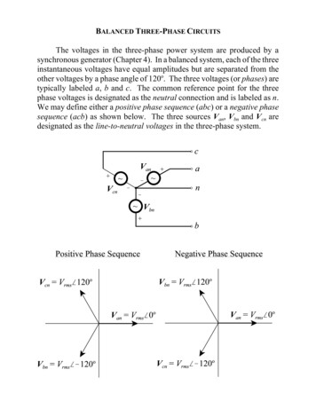
Three Phase Load Balancing and Power FactorCorrection Using a Pulse Width Modulated StaticCompensatorbyChristopher Andrew StruthersA thesispresented to the University of Manitobain partial fulfilment of therequirement for the degree ofMaster of Sciencein the Department of Electrical and Cornputer EngineeringUniversity of ManitobaWinnipeg, Manitoba@ Copyright by Christopher Struthers, 2001
1*1National LibraryofCamdaBibliothéque nationaledu CanadaAcquisitions andBibliographie ServicesAcquisitions etservices bibliographiques395 WeUington StreetOttawa O N K I A ON4canada395, nie WeUingtonOttawaW K l A WcanadaThe author has granted a nonexclusive licence dowing theNational Library of Canada toreproduce, loan, distribute or seUcopies of this thesis in microform,paper or electronic formats.L'auteur a accordé une licence nonexclusive permettant à laBibliothèque nationale du Canada dereproduire, prêter, distribuer ouvendre des copies de cette thèse sousla forme de microfiche/fïlm, dereproduction sur papier ou sur formatélectronique.The author retains ownership of thecopyright in this thesis. Neither thethesis not substantial extracts from itmay be printed or othemisereproduced without the author'spermission.L'auteur conserve la propriété dudroit d'auteur qui protège cette thèse.Ni la thèse ni des extraits substantielsde celle-ci ne doivent être imprimésou autrement reproduits sans sonautorisation.
THE UNIVERSITY O F MGNLTOBAFACULTY OF GRADUATE STUDIESa****COPYRIGHT PERMISSIONTEREE PHASE LOAD BALANCING AND POWER FACTOR CORRECTION USING APULSE WIDTH MODULATED STATIC COMPENSATORCHRISTOPHER ANDREW STRUTHERSA Tbesis/Practicum submitted to the Faculty of Graduate Studies of The University ofManitoba in partial fulfillment of the requirement of the degreeofMASTER OF SCIENCECHRISTOPHER ANDREW STRUTHERS O 2001Permission bas been granted to the Library of the University of Manitoba to lend o r sel1 copies ofthis thuis/practicum, to the National Library of Canada to microfilm this thesis and to lend or sel1copies of the film, and to University Microfilms Inc. to publisb an abstract of thW thesis/practicum.This reproduction o r copy of this thesis bas been made available by authority of the copyrightowner solely for the purpose of private study and researcb, and may only be reproduced andcopied as permitted by copyright Iaws o r with express written authorization from the copyrigbtowner.
THESIS RECORD SHEETPage Numbers89STRUTHERS, Christopher Andrew407 6& AvenueCastiegar, British Colombia VIN 1T4Graduation DateOctober 2001DefF-Master of ScienceTitle of Thesis (or Practicum)Three Phase Load Balancing and Power Factor Correction Using a Pulse Width ModulatedStatic CompensatorExaminers (and their Departments):Advisor: Dr. A. ColeDepartment of Electrical and Computer EngineeringDr. R M e d e sDepartment of Electrical and Computer EngineeringDr. D. WoodfordDepartment of Electrical and Computer EngineeringExternal ExaminerDr. 1. PapicUniversity of LjubljanaBudget #ReceivedCopies 2AppmvedAugust 3,2001Sent to LibrarySeptember 26,2001Sent
ACKNOWLEDGEMENTSFirst and foremost I would like to thank my advisor, Dr Ani Gole. Your extensive knowledge, friendly character and considerable patience have made thisthesis both enjoyable and successful.Secondly 1 would like to thank al1 my friends and fellow students in the powersystems department. 1 ieamed a lot from you al1 and greatly appreciated yourCompany. Best wishes in al1 your future endeavours.Finally, thanks goes to Manitoba Hydro for funding this research and makingit possible.
ABSTRACTThe purpose of this thesis is to demonstrate that a pulse-width-modulated staticcompensator is capable of performing three-phase load balancing and powerfactor correction. An unbalanced load is analysed using sequence componenttheory and a mathematical solution found to satisQ the load balancing andpower factor correction requirements. Two types of pulse-width modulation toimplement this theory are investigated - sinusoidal pulse width modulation andcurrent reference pulse width modulation. Control systems have been developed for both methods. Both methods have then been simulated using PSCAD/ EMTDC software with the results analysed for dynarnic response, steady stateresponse and harmonic content.
TABLE OF CONTENTSCHAPTER 1 : INTRODUCTION TO STATCOM AND LOADBALANCING APPLICATIONS1.1 THE NEED FOR COMPENSATION1.2 TRADITIONAL SOLUTION1-3 STATIC SYNCHRONOUS COMPENSATORS1.4 RESEARCH OBJECTIVESCHAPTER 2: LOAD BALANCING THEORY2.1 NOTATION2.2 SEQUENCE TRANSFORMATIONS2.3 ANALYSIS OF UNBALANCED LOAD2.3.1 Sequence Transformation of Unbalanced Load2.3.2 Power Oscillations of Unbalanced Loads2.4 ANALYSIS OF LOAD-BALANCER2.4.1 Sequence Components of Load Balancer2.4.2 Power Factor Correction2.4.3 Real and lmaginary Parts of Load Balancer Currents2.5 Example of Load Balancing SolutionCHAPTER 3: LOAD BALANCING AND POWER FACTORCORRECTION USING SINUSOIDAL PWM3.1 MATHEMATICAL ANALYSIS OF STATCOM3.1.1 Sequence Components3.1- 2 DC Transients3.1.3 Modulation of Output Voltage3.2 CONTROL SYSTEM3 2.1 Reactive Current Control3.2.2 Real Current Control
3.2.3 DC Transient Control3.2.4 Construction of the Reference Sinusoids3.2.5 Zero Sequence Filter3.2 -6 Mathematical Proof of Control System3.3 SWITCHI-NG3.4 HARMONICSCHAPTER 4: LOAD BALANCING AND POWER FACTOR CORRECTIONUSING CURRENT REFERENCE PWM344.1 C U R E N T ANALYSIS OF STATCOM344.1 . 1 Real and Reactive Current Flows344.1-2 Dynarnic Performance344.2 CONTROL S Y S E M4.2.1 Generation of the Reference Currents35364.3 SWITCHING374.4 HARMONICS384.4.1 Active Filtering384.4.2 PWM Generated Harmonies39CHAPTER 5: MODELLING OF THE SYSTEM IN PSCADKMTDC5.1 SELECTION OF SYSTEM PARAMETERS5.1.1 Leakage Reactance5.1.2 Capacitor Voltage5.1 -3 Capacitor Size5.1.4 Complete System5.2 NEW COMPONENTS5.2.1 Interpolated Switching Delay5.2.2 Power to Resistance / Inductance Calculators5.2.3 3x3 Computaîion Matrix5-2.4 Polar to Rectangular Transformation
5.3 Complete Control SystemCHAPTER 6: PSCADmMTDC SIMULATION RESULTS50536.1 S m s o r n A L PULSE WIDTH MODULATION6.1- 1 Optimal Control Settings6.1.2 Simulation Outputs6.1.3 Harmonic Analysis6.1 -4 Effects of Switching Delay6.1.5 Effects of Source Voltage Impedance6.2 CURRENT REFERENCE PULSE WIDTH MODULATION6.2.1 Optimal Control Settings6.2.2 Simulation Outputs6.2.3 Harmonic Analysis6.2.4 Effects of Switching Delay / Minimum Switching Time6.2.5 Lower Harmonic Filtering6.2.6 Effects of Source Voltage ImpedanceCHAPTER 7: CONCLUSIONS767.1 CONCLUSIONS7.2 FUTURE WORKREFERENCES-APPENDIX A INSTANTANEOUS POWER OF THREE-PHASEDELTA-CONNECTED LOADS80-APPENDIX B REAL AND REACTIVE PARTS OFLOAD BALANCER CURRENTS82APPENDIX C - REQUIRED COMPENSATOR CURRENTS FROMLOAD POWERS85
LIST OF FIGURES1.1 Example of TCR / TSC.1.2 Current Flow in TCR.1.3 Single Phase Mode1 of STATCOM.1.4 STATCOM Used for Load Balancing and Power Factor Correction.2.1 Standard and Rotated Phasor Fonns.2.2 Examples of Unbalanced Loads3.1 Single Line Diagram of STATCOM / Voltage Source Sequences3.2 Worst Case DC Transient in STATCOM Current3.3 Control Diagram for Sinusoidal Pulse Width Modulation3.4 Sinusoidal Pulse Width Modulation Signals3.5 General Format of Control System.3.6 Control of Reactive Currents.3.7 Detailed Control of Reactive Currents.3.8 Alternative Definition of Error Signals.3.9 Possible Solution for Control of Real Currents3.10 Capacitor Voltage / Real Current Control Subsystem.3.1 1 DC Transient Removal Subsystem.3.12 Output Signals from Phase Locked Loop3.13 Construction of Reference Sinusoids.3.14 Control Block Diagram for Voltage Controlled PWM3.15 Effect of Modulation Index on Switching Times.4.1 Single Phase of STATCOM / Current Source4.2 Block-Diagram of Control for Voltage PWM4.3 Exarnple of curent-hy steresis PWM.4.4 Generation of reference currents for current controlled PWM.4.5 Harrnonic Elimination using Current Controlled PWM5.1 System Parameters Used for Simulation5.2 PSCAD Schematic of Main System5.3 Interpolation of Finng Signal from SPWM
5.4Operation of New Switch-Delay Component5.5 EMTDC / PSCAD Simulation of Variable Load5.63x3 Computation Matrix Used to Calculate Reactive Current Orders5.7 Polar to Rectangular Transformation Block5.8PSCADEMTDC Implementation of Controls, Part 1 - FFT Measurements5.9PSCAD/EMTDC Implementation of Controls, Part 2 - Main5.10PSCADEMTDC Implementation of Controls, Part 3 - PWM Firing6.1 Contour Pjots of DC Errors Esed to Find Optimal PI Gains6.2Contour Plots of Negative Sequence Errors Used to Find Optimal PI Gains6.3 Contour Plots of Capacitor Voltage Errors Used to Find Optimal PI Gains6.4Simulation Outputs, Step Change from no-load io IOMW,8 MVAR phase BC6.5Simulation Outputs, Step Change from 10 MW, 8 MVAR phase BCto 10 M W , 8 M V A R on phases AB and CA.6.6Simulation Outputs, Step Change from IOMW,8MVAR on phases Ai3 and CAto no-load.6.7 Fourier Analysis of Balanced System Currents6.8Fourier Analysis of Balanced System Currents with Switching Delay6.9Fourier Analysis of Balanced System Currents with Switching Delay6.10 Distorted Current Waveforms due to Switching Delay6.1 1 Fourier Analysis of Balanced System Currents with Switching Delay6.12 Distorted Current Waveforms due to Switching Delay6.13Fourier Analysis of Balanced System Currents with Switching Delay6.14 Distorted Current Waveforms due to Switching Delay6.15Simulation Outputs, Step Change from no Load to 10 MW, 8 MVAR on phase BC.Source Voltage Impedance 1 .OW at 8006.16Contour Pfots of Negative Sequence Errors Used to Find Optimal PI Gains6.17 Simulation Outputs, Step Change from no-load to 10 MW, 8 MVAR phase BC.6.18 Simulation Outputs, Step Change from 1 OMW, 8 MVAR phase BCto 1OMW,8 MVAR on Phases AB and CA.6.19Simulation Outputs, Step Change from 1OMW, 8 MVAR on Phases AB and CAto no-load.
6.20 Fourier Analysis of Baianced System Currents716.21 Fourier Analysis of Balanced System Currents with Switching Delay726.22 Distorted Current Wavefoms due to Switching Delay726.23 Bridge Circuit Used to Draw Square-Wave Load Currents736.24 Compensation of Single Phase Square Wave Load736.25 Fourier Analysis of Square Wave Compensation746.26 Simulation Outputs, Step Change from no-load to IOMW. 8 MVAR phase BC.75
Abbreviations and symbols used in this thesis are tabulated below:Am peresComplex Constant - 1 at 120 degrees.ACAlternating CurrentCOMPCompensatorCOSCosine FunctionCRPWMCurrent Reference Pulse Width ModulationDCDirect CurrentDVRDy namic Voltage RegulatorFACTSFlexible AC Transmission SystemsFFTFast Fourier TransformGTOGate Tum-OffThyristorHVDCHzHigh Voltage DCHertzIMAGImaginary Part of Complex lovolt-amp ReactiveL-LLine to LineL-GLine to GroundMVAMegavolt-ampsMVARMegavolt-am ps ReactiveMWMegawattsPIProportional Integral ControllerPLLPhase Locked LoopPWMPulse Width ModulationREFReference
SINSine FunctionSPWMSinusoidal Pulse Width ModulationSTATCOMStatic Synchronous CompensatorsvcStatic Var CompensatorTCRThyristor Controlled ReactorTSCThyristor Switched Capaci torUPFCUnified Power Flow ControllerusMicrosecondVSIVoltage Source Inverter
Chapter 1INTRODUCTION TO STATCOM AND LOADBALANCING APPLICATIONSOngoing developments in solid-state power electronic devices have paved the way for extensiveprogress in the field of power quality. Faster, more reliable and more easily controlled powerelectroni c devices have allowed the development of Static Var Compensators (SVC 's), Dy namicVoltage Regulators (DRV's), Static Synchronous Compensators (STATCOM7s),Unified PowerFlow Controllers (UPFC's) among other Flexible AC Transmisison System (FACTS) devices. [ l ]These devices can be applied to provide power factor correction, three phase load balancing, voltage regulation, flicker control, harmonic elimination, increased network stability and better control of power flow.The main objective of this investigation is to provide three-phase load balancing and power factorcorrection using a Pulse Width Modulated (PWM) STATCOM.1.1 The Need for CompensationCertain industrial loads do not draw equal load currents from al1 three phases. Single phase railway loads and electncal arc furnaces are the two most common examples. Large unbalancedloads often result in a voltage imbalance in the power system, which thereby affects other customers. Cage induction motors are affected by even a minor voltage imbalance, which results in additional heating and unbalanced mechanical torque. Thus is it desirable to compensate a highlyunbalanced load, so that the network does not suffer the effects of imbalance.Loads with large reactive power requirements draw a lot of reactive current from the networkwhich leads to poor voltage regulation and limits the controllability and the amount of real powerthat c m be delivered. Thus it is also desirable to provide reactive power compensation to a highlyinductive load.
1.2 Traditional SolutionBoth of these compensation requirements have traditionally been satistfied using SVC 'S. [2].SVC's generaily consist of thyristors controlled reacton (TCR's), and thyristor switched capacitors (TSC's). A typical single-phase of a shunt-connected SVC is s h o w in Figure 1.1 below:Figure 1.1 : Example of TCR / TSC.The TCR valves are fired every cycle between 90 and 180 to allow a variable amount of reactive current flow. Figure 1.2 below shows the TCR currents for firing angles 10SO,120' and 160 .l( IOSOAia 120 La r 1 0i Figure 1.2: Current Flow in TCRA firing angle of 90' allows maximum reactive current flow, while an angle approaching 180 results in zero current flow.The TSC does not have this variable property however. Capacitor current is proportional to thederivitive of the voltage. Switching dunng the cycle creates a discontinuous voltage. Differentiation of the discontinuity creates unacceptable cument transients. Therefore, both valves areswitched either on or off completely throughout every cycle.However, severai TSC's switched on or off in parallel can be used to give some variation in
capacitive current. In conjunction with a large enough TCR the net current cm be varied over theentire capacitive/inductive range.For example, two TSC's each with ratings of SOKVAR, in conjunction with a TCR of SOKVARwill provide full reactive power compensation anywhere from 1OOKVAR capacitive to SOKVARinductive.Load balancing and power factor correction can be provided by connecting these branches into athree-phase delta configuration, and then controlling the required reactive curents on eachbranch.1.3 Static Synchronous CompensatorsThe advent of the Gate Tum Off (GTO) thyristor has allowed the development ofa highly flexibleSTATCOM.1Switch A/Vout1I- vcap1-Switch Bi---bOOCOLeakage inductance/i-SourceVoltageGTO Voltage Source InverterFigure 1.3: Single Phase Mode1 of STATCOM.Fig 1.3 above shows a single phase STATCOM, with the GTOYsmodelled as ideal switches.The two capacitors are charged to equal voltages in opposing polarities ( Vcap, -Vcap). Whenswitch A is closed, the output voltage, Vout, is equal to Vcap. When switch B is closed, V i isequal to -Vcap. Switch A and B are never closed at the same time.These switches, when opened and closed in a periodic manner, will create an output voltage thatis effectively sinusoidal. The switching method of interest for this research is pulse-width modu-
lation. The two modulation methods of interest in this research are Sinusoidal Pulse Width Modulation (SPWM) and Current Reference Pulse Width Modulation (CRPWM). These wilt bedescnbed fùrther in chapters 3 and 4.Altenng the modulation of the switching signals allows control of the magnitude and phase of theoutput voltage which thereby controls the real and reactive current flows to the system. Figure 1.4below shows a three phase load balancing STATCOM in greater detail. This is the mode1 analysed throughout this investigation.21GTO Voltage Source Inverter a r i a b kInductiveLoadFigure 1.4: STATCOM Used for Load Balancing and Power Factor Correction.STATCOM7sare ordinarily used for balanced three-phase reactive power compensation or balanced three-phase voltage regulation. In baianced operation, GTO pairs on each phase receive thesarne switching signais, 120' out of phase. The capacitor voltage is varied to provide differentarnounts of balanced three phase reactive currents.For a load balancing application however, differing arnounts of real and reactive current arerequired on each phase. One way of achieving this is by fixing the capacitor voltage at a certainlevel and providing three different modulation signals to each GTO pair.
STATCOM's have proven to be faster and more effective than SVC's for power factor correctionand flicker elimination in rapidly changing arc funace loads 133. It will be s h o w that they canalso be effective for load balancing applications.1.4 Research ObjectivesThe main objective of this research is to design and successfully simulate a three phase load balancing STATCOM, as shown in figure 1.4.Two methods of pulse width modulation will be investigated, voltage controlled sinusoidal pulsewidth modulation and current reference pulse width modulation. They will be compared in termsof dynarnic performance, harmonic analysis and steady state performance.The additional property of active filtenng [4] will be applied to the current reference pulse widthmodulation.
Chapter 2LOAD BALANCING THEORY2.1 NOTATIONTwo different frames of reference for real and imaginary parts of phasor quantities are usedthroughout this thesis. To avoid confusion, strict notation to differentiate between the two hasbeen adopted.The first reference frame will be referred to as the standard phasor forrn. This is where real andimaginary parts of each phase are in the same plane, so they may be added or subtracted from oneanother. AH phasors in the standard form can therefore be used in Kirchoffs current and voltagelaws. The standard form, with real and imaginary parts will be denoted as follows:*9- l a la,, j l u ,Ic Ic,, jlc,,l b l b , JI&,,(2.1)The second reference frame will be referred to as the rotated fom, whereby phases B and C havebeen rotated by 1120' and -120' respectively. This means that vectors associated with phase Bwill use the voltage phasor of phase B as the reai axis, and likewise for phase C.The constant a will be used to denote 1 L 120" and a2for 1 L- 120" . Multiplication of phasors bythis constant performs the required rotations. The 'a' and 'a2'symbols will always appear in thenotation for the rotated reference frarne to differentiate from the standard frame.Notation for the rotated form is shown as follows: la la,, jlu,- a l b [ a l b ] , j [ a l b ] ,a2 Iç 22[ a k ] r e J [ U ICI;,(2.2Note that phase A does not change. Both the values and notation remain identical.When descnbing real and reactive currents on each phase, the rotated fonn is more useful. A realor imaginary value in the rotated form corresponds exactly to a real or reactive current value, withrespect to the individual phase voltage.
Take for example, a selection of balanced three phase currents:/ a 3.16sin(ot 18")/b 3.16sin(o! - 102")Ic 3.16sin(ot 138")(2.3)In standard phasor f o m , they will be expressed as follows:With the real and imaginary parts being:Ib,,Ib,,,,la,, 3Inim 1 -0.634-3.098Ic,, -2.366Ic,, 2.098(2.5)In rotated phasor form, where phases B and C are shifted by a and a', they will be expressed as:*aib7-J 3.16L18"a-lc 3 j 13.16L18O 3 j 1 (2.6)With the real and imaginary parts being:la,,la,, 3[alb],,[alb],1 31[a2 lc],, 39[ ' I C ] 1 This allows us to see immediately that the currents ail consist of real current, magnitude 3,plus reactive current, magnitude 1. Figure 1.5 below shows this graphicailyStandard Phasor FonnRotated Phasor FonnFigure 2.1: Standard and Rotated Phasor Forms.(2.7)
2.2 SEQUENCE TRANSFORMATIONSSequer cetransformations are an exceptionally useful tool for analysing unbalanced loads and formulating a solution to them [ 5 ] .3 - Given three phasor quantihes for currents in standard form (la,Ib, Ic), the positive negative and 3 9zero sequences ( II,4,Io ) can be calculated using the following relation:Where a lL120"(2.8)The relation can be inverted as follows:Where a 1L120"2.3 ANALYSIS OF UNBALANCED LOAD2.3.1 Sequence Transformation of Unbalanced LoadA perfectiy balanced load current will contain no negative sequence component and no zerosequence component. The ultimate goal of a load-balancer is to remove these components. Notethat this thesis is concemed only with star-ungrounded or delta-connected loads, so zero sequenceis not a concern.Positive sequence current of a load at unity power factor will contain no imaginary component.The load-balancer cm be altered to also remove the positive sequence imaginary component ofthe load current to provide power factor correction.Fig 2.1 shows examples of various delta-connected resistive Ioads, real-time currents and the cor-
3responding sequence components ( I , , 12,Io ) of the load currents.Figure 2.2: Examples of Unbalanced Loads2.3.2 Power Oscillations of Unbalanced LoadsInstantaneous power of a balanced load is a constant non-sinusoidal value equal to the RMSpower. However, instantaneous power of an unbalanced delta-connected load will oscillate attwice the system frequency, similar to that in a single-phase load.This phenornena is best understood in terms of sequence components. Assuming a perfectly balanced source voltage, positive sequence currents provide constant power with a value equal to thetotal RMS power. Negative sequence currents cause the oscillations in power. The average valueof these oscillations is zero. This means that negative sequence currents do not alter the total netenergy flowto the load.Equation 2.1 shows the relationship between instantaneous power (P(r)), R M S Line to Ground Voltage (VLG)and sequence components of the load currents (IlJ2 ). Refer to Appendix A for the
derivation.(2.11)P ( f ) 3 VLG(I,REAL-I2RL? LCOS( I ) I i . 4 f . 4 i nf )( )2 0hThe oscillations in instantaneous power become important when determining the energy ratingsof the compensator. The storage capacitor must be large enough to absorb these energy oscillations without any detriment to performance. This will be discussed fùrther in chapter 5.2.4 ANALYSIS OF LOAD-BALANCER2.4.1 Sequence Components of Load BalancerAs mentioned previously, a balanced load will contain only positive sequence currents. This canbe achieved by having the load-balancer produce negative sequence currents which are exactlyopposite to those in the unbalanced load.For exarnple, if the load contains negative sequence currents of0 . 3 3 then6 0 the compensatormust provide negative sequence currents of - 0 . 3 3 p u 6 0 0.Only three-wire loads are being considered for this research, so zero sequence is ignored. However, it is possible to develop a more complicated four wire STATCOM that is capable of cornpensating for zero sequence [6].2.4.2 Power Factor CorrectionPower factor correction can be added to the controls of a load-balancer fairly easily. It is simply amatter of removing the imaginary part of the positive sequence load current as well as the negative sequence. This will however require a load-balancer of higher rating.2.4.3 Real and Imaginary Parts of Load Balancer CurrentsOnce the current sequence components required from the load balancer have been calculated, it isadvantageous to convert these into individual per-phase current orders. These orders are bes:
expressed in real and i magi nary (reactive) parts.Matrices (2.2)- (2.3) below show the relationship berneen compensator current sequence campo *44, nents ( 1 ,J , ) and the corresponding phase currents in rotated fom (la,a l b , a - I c ). The termC"ICHARGE" is the net real current required to keep the capacitor charged to the reference voltage. This value will be close to zero during steady state. Refer to appendix B for the denvation.2.5 Example of Load Balancing SolutionTake for example a single phase load of 1OMW, 8MVAR on phase BC, where the line voltage is1OKV RMS.Line to ground voltages are:-So line-line voltage on phase BC is: Vbc V b - VC 101-90"Load currents c m now be solved using the relation I (S,V *:Now it is possible to calculate the sequence components of the load currents:
As expected, there is no zero sequence. The compensator will be required to provide opposingnegative sequence real and imaginary currents for load balancing, in addition to positivesequence imaginary currents for power factor correction:Equation (2.12) can then be used to find the real and imaginary parts of the requiredcompensator currents. Capacitor charging current is assumed to be negligible (O):This shows that in order to balance the load and correct the power factor, the compensator mustdo the following:Draw 0.577KA and O. 1 1 1K A real current from phases A and C respective1y, and deliver the sum,0.689KA, to phase BDraw 0.193KA and 1.193KA of leading reactive cument from phases B and C.Net real power transfer is zero.The sum of the reactive currents is 1.386KA. Multiplication by the line voltage, S.77KV7showsthe net reactive power transfer is 8 MVAR capacitive, the same quantity consumed by the load.
This solution can be proved by rotating the compensator currents back to standard phasor form:Then summated with the load currents to find the total system currents:The solution shows that al1 three system currents are of identical magnitude, and perfectly inphase with their respective voltages.Load balancing and power factor correction will therefore be accomplished if the compensatorcan provide the required currents to the load.
Chapter 3LOAD BALANCING AND POWER FACTORCORRECTION USING SINUSOIDAL PWM3.1 MATHEMATIC.4L ANALYSIS OF STATCOM3.1.1 Sequence ComponentsThe clearest method of analysing unbalanced currents and voltages in the system is to use superposition of sequence components. Figure 3.1 below shows the single line diagram of the STAT-COM system in terms of positive and negative sequence components. The STATCOM ismodelled as a voltage source with both real and imaginary parts making up the positive and negative sequence components.The source voltage is assumed to be balanced and set as the reference phase. Thus it contains onlya positive sequence real part. Zero sequence is ommitted due to the assumed delta windings.POSITIVE SEQUENCE-SourceSTATCOMNEGATIVE SEQUENCEO'V, VCZm j V C Z 1 SourceFigure 3.1: Single Line Diagram of STATCOM / Voltage Source Sequences
Using Ohms law and superposition, the sequence components of the output currents can be calculated in the standard non-rotated forrn as follows:Breaking down the equations into these real and imaginary sequence components will prove to benecessary when analysing the control sy stem.3.1.2 DC TransientsOne aspect which must be considered when using voltage control are the undesirable DC transients that occur in the output current. The output current is related to the integral of the voltageacross the transformer leakage reactange. This results in a constant of integration whenever achange is made to the voltage.iL(t) #vC(t)- vs(t) c(3.2)Figure 3.2 below illustrates the DC Transient in a worst-case scenario where the inductor voltage(STATCOM voltage minus system voltage) undergoes a 180 phase shift at a current maximum.Lefi alone this DC transient will follow an exponential decay depending on the damping withinthe circuit. It is preferable, however, to remove this DC much faster using controlsFigure 3.2: Worst Case DC Transient in STATCOM Current.
3.1.3 Modulation of Output VoltageThe finng pulses to the GTO's are constructed using a reference sinusoid compared against a tri-angular wave. This technique is commonly known as sinusoidal pulse width modulation (SPWM)[l]. Figure 3.3 below shows the basic control diagrarn for a single phase SPWM system.A voltage reference signal is constructed using three components. The first component is a sinusoid directly in phase with the source voltage to control the real current flow. The second component is a sinusoid in quadrature with the source voltage to control the reactive current flow.Lastly, a DC cornponent may be necessary for removing DC transients in the output current.This reference sinusoid is com pared against a triangular wave. W henever the reference sinusoid isgreater than the triangular wave, the VSI is fired to switch a positive output. Vice-versa for a negative output. Figure 3.4 overleaf shows an example of these three components, the resulting reference sinusoid, and the output voltage produced from the cornpensator.Direct Sinusoid toControl ReactiveCurrentTotal ReferenceSinusoid Q.Quadrature Sinusoidto Control RealCurrentDC Componentto Control DCCurrent TransientsB COMPARITORComplementaryFiring Pulses toA ,B;Q lGTOPairA B;Q O -QTriangular WaveFigure 3.3: Control Diagram for Sinusoidal Pulse Width Modulation
1--.--DircctQuadrature----DCOTotal. -.-Ir rL-outputVoltage.-.-.- - -.-FundarncntalComponcntI**-.-cap VoltsFigure 3.4: Sinusoidal Pulse Width Modulation SignalsIt can be seen that the findamental component of the resulting output voltage (Vc) is equal to thereference sinusoid (Ren multiplied by half of the VSI's capacitor voltage (VCap).The RMS relationship is given by :-VCaVc Ref. (3-3)The peak-value of the reference sinusoid, not including the DC component, will be referred to asthe "modulation index". The ratio of triangular wave frequency to reference sinusoid frequencywill be referred to as the "modulation ratio"
3.2 CONTROL SYSTEMThe requirements of the control system are as follows:To satise a load-balancing solution, different real and reactive currents are requiredfrom each phase. Therefore, each GTO pair
3.2.3 DC Transient Control 3.2.4 Construction of the Reference Sinusoids 3.2.5 Zero Sequence Filter 3.2 -6 Mathematical Proof of Control System 3.3 SWITCHI-NG 3.4 HARMONICS CHAPTER 4: LOAD BALANCING AND POWER FACTOR CORRECTION USING CURRENT REFERENCE PWM 34 4.1 CURENT ANALYSIS OF STATCOM 34 4.1 .1 Real and Reactive Current Flows 34 4.1 -2 Dynarnic Performance 34