Transcription
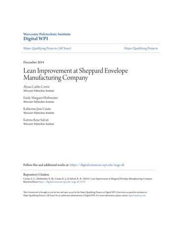
SD-25-50062The Sheppard Active Steering System by Bendix CVSVehicle Equipped with theSheppard Active Steering System by Bendix CVSTrackable Lane LinesCompatible WindshieldMounted CameraNOT TO SCALEFigure 1 – The Sheppard Active Steering System by Bendix CVS Uses a Windshield-Mounted CameraBendix AutoVue FLC-20 CameraBendix safety technologies complement safe drivingpractices. No commercial vehicle safety technologyreplaces a skilled, alert driver exercising safe drivingtechniques and proactive, comprehensive drivertraining. Responsibility for the safe operation of thevehicle remains with the driver at all times.DESCRIPTIONThe Sheppard Active Steering System by BendixCVS is a driver assistance system, helping the driverwith a suite of steering assist features and driverassist steering features integrated with the Bendix FLC-20 camera, Bendix Wingman Fusion or acompatible third party camera. The active steering systemdoes not replace the driver or driving skills.The driver is solely responsible for maintaining controlof the vehicle with both hands on the steering wheel.The active steering system combines unique activesteering technology with a forward-facing camera for activelane correction. This system helps mitigate potential sidecollisions and lane-departure related accidents, as well asincrease driver comfort.Magnetic Torque OverlaySteering GearActive SteeringElectronic ControlUnit (ECU)Figure 2 – System ComponentsAdditional Reference Information For installation of the Bendix AutoVue FLC-20 camera see Bendix Service Data sheet SD-64-20124,available on Bendix.com. For installation of the steering gear see the Sheppard D-Series Integral Power Steering Gear manual,available on RHSheppard.com. For installation of the ECU see the OEM serviceinformation.1
Improper use of the Sheppard Active SteeringAssist System by Bendix CVS can result in a collisionresulting in property damage, serious injuries, ordeath. Be sure to read, understand, and carefullyfollow the instructions this document.Due to the inherent limitations of image recognitiontechnology, camera-based safety technology — onrare occasions — may not be able to detect or maymisinterpret lane markings. At these times, alertsmay not occur, or erroneous alerts may occur.Bendix safety technologies complement safe drivingpractices. No commercial vehicle safety technologyreplaces a skilled, alert driver exercising safe drivingtechniques and proactive, comprehensive drivertraining. Responsibility for the safe operation of thevehicle remains with the driver at all times.This product may expose you to chemicalsincluding Nickel, which is known to the State ofCalifornia to cause cancer and birth defects or otherreproductive harm. For more information, go toP65Warnings.ca.gov.IMPORTANT: It is the responsibility of the driver to remainvigilant and change driving practices depending on trafficand road conditions.2
DRIVER ASSISTANCE FEATURESLANE KEEP ASSIST (LKA) Detects lane markings and evaluates relative vehicleposition Recognizes when the vehicle begins to drift towardsthe lane markings Distinguishes between planned lane changes andlane drifting Intervenes before the vehicle reaches the lane markings For additional information, see the Bendix AutoVue FLC-20 Camera Service Data sheet SD-64-20124available for download on bendix.com. Is compatible with later versions of Bendix Wingman Fusion systems.LDW WINDSHIELD MOUNTING BRACKET The bracket that holds the camera secure and keepsit facing the correct direction to successfully determinelane width and position. See Figure 3. Automatically applies a correction torque to the steeringwheel Smoothly releases steering torque as soon as thevehicle trajectory is re-established The system enables the driver to suppress or overridesteering torque LKA is activated at 37 mph / 60 kphBendix AutoVue FLC-20 CameraCameraBracketSTEERING ASSIST Speed Dependent Steering Assist - Provides variablesteering assist based on vehicle speed. It helps thedriver experience easier steering at low speeds anda firmer steering response at higher speeds. It alsoaids the driver by reducing fatigue and helps the drivermaintain better control of the vehicle.Figure 3 – Bendix AutoVue FLC-20 Camera & Bracket Active Return - Helps to reduce driver fatigue througheasier maneuvering by returning the steering wheel tothe center position at lower vehicle speeds. Crown/Side-Wind Compensation - Helps to reducedriver fatigue, or steering effort, by helping keep thevehicle straight during heavy side winds, crownedroads, or some alignment issues. Road Disturbance Compensation - Helps improvedriver comfort by reducing steering wheel vibrationtypically caused by road disturbances like potholes,road debris, or other bumps in the road.SYSTEM COMPONENTS ECUFigure 4 – Lane Keep Assist Electronic Control Unit (ECU)ACTIVE STEERING ECUBENDIX AUTOVUE FLC-20 CAMERA Connector The forward-facing camera tracks the lane markers andprovides the lane characteristics for the left and rightmarker to the Sheppard Active Steering System byBendix CVS system over the vehicle communicationnetwork. In addition, the system also providesinformation on when the lane departure warningswill be suppressed, allowing the LKA feature to besuppressed at the same time. See Figure 3. The Electronic Control Unit (ECU) for the SheppardActive Steering System by Bendix CVS is a standaloneunit designed to work with J1939 Vehicle CAN and aforward-facing lane sensing camera. See Figure 4.3
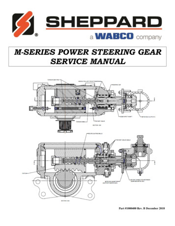
MAGNETIC TORQUE OVERLAY POWERSTEERING GEAR Perform a visual inspection to ensure proper installationand functionality. The power steering gear with magnetictorque overlay should be clean and free of fluid. Allconnectors around the gear should be connected andsecured. See Figure 1. For additional service and troubleshooting informationsee the Sheppard D-Series Integral Power SteeringGear manual available online from the CustomerService tab on RHSheppard.com.STARTING BENDIX ACOM PRODIAGNOSTIC SOFTWAREThe Bendix ACom PRO Diagnostics Software canbe started from the desktop shortcut, or from the mainWindows screen with “Start Programs Bendix AComPRO Diagnostics Software”. To begin, the technicianselects “Connect” from the upper panel. See Figure 5.TROUBLESHOOTINGSAFETY GUIDELINESRead and follow the General Safety Guidelines shownon Page 2 of this document.IMPORTANTAll vehicle Diagnostic Trouble Codes (DTCs)related to the engine, transmission, instrumentcluster, engine cruise control, and Bendix ABS,ATC, or ESP systems must first be resolved, withno DTCs present during the vehicle operationwhile in cruise control, prior to running Bendix ACom Pro diagnostics to resolve Sheppard Active Steering System by Bendix CVS DTCsfaults.IMPORTANTSystem Problems. If a problem with the Sheppard Active Steering System by Bendix CVS is detected, itshould be serviced as soon as possible to restore fullfunctionality. The vehicle does not need to be takenout of service, the Lane Keep Assist (LKA) will bedeactivated.4Figure 5 – Starting Bendix ACom PRO DiagnosticSoftwareNOTE: When using ACom PRO Diagnostic Software forthe first time, the service technician will need to check thecommunication adapter for the Sheppard Active SteeringSystem by Bendix CVS controller. The technician willneed to indicate which communication protocol to use with“Application Settings Preferences Connection”. Oncea successful connection has been made, these steps willno longer be necessary. See Figure 6.The Bendix ACom PRO Diagnostic Software for ActiveSteering System User Guide is available in the softwaredownload and should be used as a reference to all functionsof the ACom PRO service tool.
Figure 6 – Bendix ACom Diagnostic Software –Hardware Interface ScreenREADING DIAGNOSTICTROUBLE CODES (DTCs)If the system generates a Diagnostics Trouble Code (DTC),where a lamp or icon is illuminated on the instrumentcluster, use a current version of Bendix ACom PRODiagnostic Software to troubleshoot. Select “Sheppard Active Steering by Bendix CVS” from the list on the leftpanel. Read the DTCs from the list on the top-right panel.See Figure 7.DIAGNOSTIC TROUBLE CODES (DTCs)Use a J1939 detection software to find the DTC code(s).Then go to Table 1 on page 6 to identify the appropriateservice action code needed to remedy the issue.Sheppard Active Steering System by Bendix CVSFigure 7 – Vehicle Selection Screen5
DIAGNOSTIC TROUBLE CODES (DTCs) AND CORRECTIVE ACTIONDTCSPN516700FMINameDescription0System Thermal ErrorTemperature HighHighTemperatureof ECU3Device Power- VoltageAbove ThresholdOver VoltageVBATT 32VBATT 324Device Power- VoltageBelow ThresholdUnder VoltageVBATT 9VBATT 95Steering AssistHydraulic PressureOpen CircuitOpen CircuitVolt 0.5 for L and R3Steering AssistHydraulic PressureShort CircuitShort Circuit2Coil Implausible DataOut of RangeCurrentCommand10Coil Current Stuck516701516702ECU H BridgeShort to BatteryReset ConditionCorrective ActionTemp 115 C for 5 seconds Temp 95C for 5 secondsPerform ignition cycle.Ignition ResetDiagnose eitherpressure sensor,wiring, or connection.(Refer to connectorpinout page 11.)Coil Current -5 amps orCoil Current 5 ampsIgnition ResetCheck coil connection.Potential coil and/orElectronic Control Unit(ECU) replacementor software update.Out of RangeCurrentCommandActual Measuredcoil current within 5percent toleranceIgnition ResetPotential coil/wiring update orsoftware update.Short to BatteryWhen no drivers are ON:Voltage on coil A 5VorVoltage on coil B 5VorWhen LS1 is ON: Current oncoil A in positive direction(A-Coil-I-Plus) 0AorWhen LS2 is ON: Current oncoil A in negative direction (Ignition ResetReplace the ECU.Ignition ResetReplace the ECU.5175543Failure ConditionVolt 4.5 for L and RWhen no drivers are ON:Voltage on coil A 5V516222orVoltage on coil B 5Vor4ECU H BridgeShort to GroundShort toGroundWhen HS1 is ON: Currenton coil A in positivedirection (A-Coil-I-Plus) 0AorWhen HS2 is ON:Current on coil A innegative direction(A-Coil-I-Minus) 0ATable 1 – Diagnostic Trouble Codes6
DIAGNOSTIC TROUBLE CODES (DTCs) AND CORRECTIVE ACTION - CONTINUEDDTCSPNFMINameDescriptionFailure ConditionReset ConditionCorrective ActionWhen LS1 is ON: Voltageon coil A 5V then LS 1is NOKorWhen LS2 is ON: Voltageon coil B 5V then LS2is NOK2ECU H Bridge NOKNOKorIgnition ResetWhen HS1 is ON: voltageon coil A 5V then HS1is NOKor516222When HS2 is ON:voltage on coil B 5Vthen HS2 is NOKReplace the ElectronicControl Unit (ECU).When the measuredvoltage at A and B 0when Low Side 1 Driveris OFF5ECU H Bridge OpenloadorIgnition ResetFailureLSS1-WL1-IN 0 (Pin 4)LSS1-WL1-IN 1SW FaultWakeup not configuredcorrectly (Mismatch inWakeup input) (CANwake up but ignitionline is connected)Wakeup inputconfigured correctly(Remove ignition line incase of CAN wake up)Using Bendix ACom PRO perform theEnd of Line (EOL)configuration tomatch the wiring.EOL Calibrationperformed (pressuresensor trimming flag 1 or coil polaritycheck flag 1)Using ACom PROperform the EOLcalibration.OpenloadWhen the measuredvoltage at A and B 0 when Low Side2 Driver is OFF5167053Warning Lamp Failure19Network ConfigurationMismatch13System ConfigurationCalibration Data setNot ProgrammedSW FaultEOL Calibration notperformed. (Pressuresensor trimming flag! 1 or coil polaritycheck flag ! 1)12System ConfigurationBad DeviceSW FaultFlash Memory ErrorIgnition ResetReflash to removememory failure19System ConfigurationSoftware VersionSW FaultVersion Mismatchon DM13No Version MismatchMatch the softwareversion - Reflash thecorrect software.5Vehicle CAN BUS OFFCAN FaultBUS Open/ ShortBUS ConnectedVerify J1939 datais on the vehiclecommunications bus.5201945Proprietary CANBUS OFFCAN FaultBUS Open/ ShortBUS ConnectedCheck if the CAN busspeed of the radarand camera's privateCAN are identical709CAN TO CCVS1CAN Time OutTimeout 300 ms and NoCAN NO BUSCONNECT DetectedCCVS 1 Transmitting11219CAN TO EBC1CAN Time OutTimeout 300 ms and NoCAN NO BUSCONNECT DetectedEBC1 tranmitting516706516707520193Table 1 – Diagnostic Trouble Codes - ContinuedCheck the sendingECU for properfunction andactive faults.7
DIAGNOSTIC TROUBLE CODES (DTCs) AND CORRECTIVE ACTION - CONTINUEDDTCSPNFMINameDescriptionFailure ConditionReset ConditionEBC2 transmitting9049CAN TO EBC2CAN Time OutTimeout 300 ms andNoCAN NO BUSCONNECT Detected1909CAN TO EEC1CAN Time OutTimeout 300 ms andno CAN NO BUSCONNECT DetectedEEC1 transmittingCAN Time OutTimeout 300 ms andNoCAN NO BUSCONNECT DetectedFLI2 transmittingCAN Time OutTimeout 300 ms andNoCAN NO BUSCONNECT DetectedVDC1 transmittingCAN Time OutTimeout 300 ms andNoCAN NO BUSCONNECT DetectedVDC2 transmittingCAN Time OutTimeout 300 ms andNoCAN NO BUSCONNECT DetectedAEBS transmittingCAN Time OutTimeout 300 ms andNoCAN NO BUSCONNECT DetectedOEL transmittingCAN Time OutTimeout 300 ms andNoCAN NO BUSCONNECT DetectedFLIC transmitting1 signal 00 signal 11 signal 00 signal 11702181418075676587699999CAN TO FLI2CAN TO VDC1CAN TO VDC2CAN TO AEBSCAN TO OEL97519CAN TO FLIC7019CAN OR CCVS1PRK BRK SWTCAN Out ofRange Signal56319CAN OR EBC1ABS CRTL ACT56219CAN OR EBC1ASRBrk CRTL ACTCAN Out ofRange Signal1 signal 00 signal 156119CAN OR EBC1ASREng CRTL ACTCAN Out ofRange Signal1 signal 00 signal 1112119CAN OR EBC1EBS BRK SWTCAN Out ofRange Signal1 signal 00 signal 152119CAN OR EBC1 EBSBRK PDL POSN PERCAN Out ofRange signal100 signal 00 signal 10090419CAN OR EBC2FA SPDCAN Out ofRange signal64254 signal 00 signal 6425419019CAN OR EEC1ENG SPDCAN Out ofRange signal64255 signa l 00 signal 64255287619CAN OR OELTRN SIG SWTCAN Out ofRange signal2 signal 00 signal 2Table 1 – Diagnostic Trouble Codes - Continued8Corrective ActionCheck the sendingElectronic ControlUnit (ECU) forproper functionand active faults.
DIAGNOSTIC TROUBLE CODES (DTCs) AND CORRECTIVE ACTION - CONTINUEDDTCSPNFMINameDescriptionFailure ConditionReset Condition171119CAN OR FLI2 FWDLANE TRK RCAN Out ofRange signal1 signal 00 signal 1171019CAN OR FLI2FWD LANE TRK LCAN Out ofRange signal1 signal 00 signal 1747419CAN OR FLI2DRV ALRT LVLCAN Out ofRange signal100 signal 00 signal 100747519CAN OR FLI2 DRVALRT WAR STATECAN Out ofRange signal3 signal 00 signal 3181619CAN OR VDC1 ROPENG CON ACTIVECAN Out ofRange signal1 signal 00 signal 1181819CAN OR VDC1 ROPBRK CON ACTIVECAN Out ofRange signal1 signal 00 signal 1181719CAN OR VDC1 YCENG CON ACTIVECAN Out ofRange signal1 s ignal 00 signal 1181919CAN OR VDC1 YCBRK CON ACTIVECAN Out ofRange signal1 signal 00 signa l 1562419CAN OR VDC1TRLR VDC ACTIVECAN Out ofRange signal1 signal 00 signal 1567619CAN OR AEBS FORCOL AEBS STATECAN Out ofRange signal7 signal 00 signal 7Corrective ActionCheck the sendingElectronic ControlUnit (ECU) forproper functionand active faults.Check the parameterset of the sensor.Check the sendingECU for properfunction andactive faults.180819CAN OR VDC2YAW RATECAN Out ofRange signal3.92 signal -3.923.92 signal 3.92180919CAN OR VDC2LAT ACCCAN Out ofRange signal15.687 signal - 15.68715.687 signal 15.687180719CAN OR VDC2STR WHL ANGCAN Out ofRange signal31.374 signal -31.37431.374 signal 31.374975119CAN OR FLIC LNKP ASST ENCAN Out ofRange signal1 signal 00 signal 1976019CAN OR FLICReqActSteeringDriverPrf MdCAN Out ofRange signal1 signal 00 signal 19CAN NO BUSCONNECTOpen FaultCANNo (non UDS) messagespresent on vehicle CANfor 250 ms at all (notlimited to messagesexplicitly received by unit)At least one nondiagnostic messagereceivedVerify J1939 datais on the vehiclecommunicationsbus bar.2Lane DirectionQualifierMismatchin cameraLeft Right LaneInformation SAFE InvalidLeft Right LaneInformationSAFE ValidVerify that thevoltage at thecamera connector isgreater than 9 VDC.19CAN OR VP131 XLCS HazardDetectedCAN Out ofRange SignalSignal 0 OR sinal 2 OR signal 30 signal 1ORsignal 4Check the sendingECU for properfunction andactive faults.520195520196520197Check the sendingECU for properfunction andactive faults.Table 1 – Diagnostic Trouble Codes - Continued9
CONNECTOR PIN IDENTIFICATIONPins X2.19 through X2.25Pins X2.1 through X2.18Unsealed (Carrier) Housings for AMPMCP 1.5 Receptacle InsertsPinsColorKeyTYCO Number25BlackA1-1718484-118BlackAMP MCP 1.5 Receptacle Insert-1718489-1AMP MCP 2.8 Receptacle Insert7Natural-1718488-1Figure 8 – Connector X2Pin 1-18: 1241374-2Figure 9 – Terminals for Connector X210Pin 19-25: 1-968851-1
CONNECTOR PIN IDENTIFICATIONPinPin NameFunctionX2.1PRESSURE SENS 1Pressure signal (left sensor)X2.2PRESSURE SENS 2Pressure signal (right sensor)X2.3PRESSURE SENS GNDPressure sensor GNDX2.4PRESSURE SENS SUPPLYPressure sensor supplyX2.10VEH-CANLVehicle CAN LowPin Size(Area)X2.5X2.6X2.7X2.8X2.9X2.11VEH-CANHVehicle CAN HighX2.12SYS-CANLSystem CAN LowX2.13SYS-CANHSystem CAN HighX2.16COIL CURRENT AOutput current (5A)X2.17COIL CURRENT BOutput current (5A)X2.19WL1Warning LampX2.20TRM-15Ignition / Terminal 15X2.21SWITCH1Input Switch for LKASX2.22TRM-30AUbat / Terminal 30AX2.24SWITCH1 GNDInput Switch GNDX2.25TRM-31AGND / Terminal 31A.5 mm2X2.14X2.15X2.182.5 mm2X2.23Table 2 – Connector Pin11
PRESSURE SENSOR, COVER,AND GASKET REPLACEMENTIf a pressure sensor has been identified as faulty ordamaged, it must be replaced. (A service kit is availablefrom R.H. Sheppard.) Once the faulty or damagedpressure sensor is removed, follow the steps below for theinstallation of the new sensor.1. Align the gasket and pressure sensor with the half circlecut-out in each part. See Figure 10.2. Align the pressure sensor and gasket on the bearingcap. See Figure 10.3. Hand start and torque the front right, and back leftpressure sensor bolts to 13-16 ft-lb (17.6-21.7 Nm) withthe 5 mm hex (Allen ) bit. See Figure 10.PressureSensor4. Remove the alignment fixture (if used) and install thepressure sensor cover by aligning the bottom tabs withthe open bolt holes. See Figure 11.5. Hand start and torque the front left and back right boltsto 13-16 ft-lb (17.6-21.7 Nm) through the tabs of thepressure sensor cover with the 5 mm hex (Allen) bit.See Figure 11.MAGNETIC TORQUE OVERLAYSTEERING GEAR AND ECUREPLACEMENTTo replace the steering gear or the ECU, please contactthe Bendix Tech Team or Sheppard Technical Support.See page 13.PressureSensor BoltsPressureSensor BoltsGasketCut-OutMagnetic TorqueOverlay SteeringGearFigure 10 – Pressure Sensor and Gasket12Figure 11 – Bolt Installation
Additional support at bendix.com / 1‑800‑AIR‑BRAKE (1‑800‑247-2725), option 2For the latest information, and for downloads of the Bendix ACom PRO Diagnostics software, and its User Guide, visitthe Bendix website at: bendix.com.ADDITIONALSUPPORTFor direct telephone technicalsupport, the BendixTech Team is available at 1-800-AIR-BRAKE (1-800-247-2725),option 2. Follow the instructions in the recorded message. Representatives are available to assist you Monday - Thursday,8 a.m. - 6 p.m. ET and Friday, 8 a.m. - 5 p.m. ET.The Bendix Tech Team can also be reached by email at: techteam@bendix.com.R.H. Sheppard Technical Support 1-800-274-7437The Sheppard hours are: Representatives are available Monday – Friday, 7 a.m. to 6 p.m. ET.Representatives can also be reached at: serviceweb@rh-sheppard.com.13
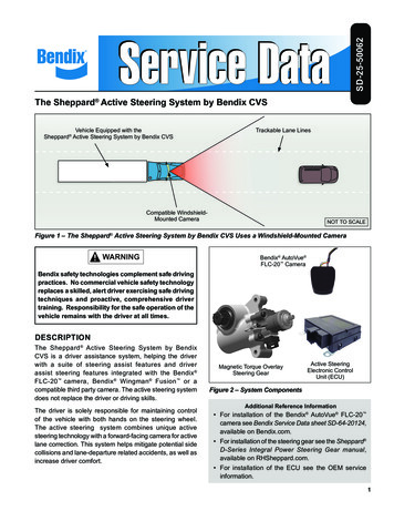
Figure 13 – System Schematic1413121514181110Tin, Twist, and SolderOver Exposed WireDetail A120 OhmHeat ShrinkHeat ShrinkTwisted Pair191716Heat ShrinkHeat ShrinkHeat Shrink8Heat ShrinkTwisted PairHeat ShrinkHeat ShrinkMS3102 MS3106E1R16S-1P6S-1SHeat Shrink7Twisted PairYellow TXL 20 AWG 3MGreen GXL 20 AWG 3MRed GXL 18 AWG 3MBlack GXL 18 AWG 3MGreen GXL 20 AWG 3MViolet GXL 20 AWG 3MGray GXL 20 AWG 3MBlue GXL 20 AWG 3MGreen TXL 18 AWG 3MYellow TXL 18 AWG 3MBlack TXL 14 AWG 3MRed TXL 14 AWG 3MOrange TXL 14 AWG 3MDetail A9Heat Shrink651342
SYSTEM SCHEMATIC KEYSystem Schematic Key (See page ?)1PinsColorKeyTyco P/N25Black-1718484-1AMP MCP 1.5K, Contact2TE Internal Number:1241374-1TE Internal Number:1355036AMP MCP 1.5K Receptacle Insert3PinsColorKeyTyco P/N18Black-1718489-1AMP MCP 2.8Receptacle Insert45PinsColorKeyTyco P/N7Natural-1718488-1Pins OnlyTE P/N: 1534097-1TE P/N: 1534101-16TE P/N: 5-963715-57Nylon Sheath from E.G. Manufacturer8Heat Shrink E.G. from 3M9120 Ohm 5% Resistor, Tinned, and Twisted with Line andSoldered, Shrink Tube Covered - Qty 110Recommend 5A Fuse11Free Ended Leads, User Suit to Application12TE Pins P/N: 2-964298-113Delphi Connector P/N: 1549844314Molex Pins P/N: 33012200315Molex Connector P/N: 31404-621316Twisted Pair CAN (Lines should have no fewer than 1 turnper 25 mm)17All Tolerances /- 5 mm (unless otherwise specified)18All Crimp Terminals to be Fastened Per the ConnectorManufacturer Specifications (unless otherwise specified)19TE P/N: MS3102R16S-1P, TE P/N: MS3106E16S-1S,TE P/N: 97-79-513-8 (boot on both male and female sides)15
Log-on and Learn from the BestOn-line training that's available when you areVisit brake-school.com.24/7/365.SD-25-21025 Rev. 000 2020 Bendix Commercial Vehicle Systems LLC, a member of Knorr-Bremse 10/20 All Rights Reserved.16Printed on recycled paper
Active Steering by Bendix CVS" from the list on the left panel. Read the DTCs from the list on the top-right panel. See Figure 7. DIAGNOSTIC TROUBLE CODES (DTC s) Use a J1939 detection software to find the DTC code(s). Then go to Table 1 on page 6 to identify the appropriate