Transcription
WABCO AIR COMPRESSORINFORMATION and COMPONENTSCUMMINS , MACK , & VOLVO
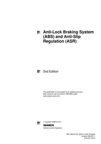
WABCO HEAD MMINSISXSS318SS31885MM18.7 CFM85MM18.7 CFM¾ - 16STORFITSCOMPRESSOR 8 – 1.5STORFITSCOMPRESSOR #’S9111535100X368190436819023104216
91115393129111549202MACKSS31885MM18.7 CFMNot available at this time½”STORFITSCOMPRESSOR 9AMCUMMINSSS25075MM¾” - 16STOR18.7 CFMALLHEAD ASSEMBLIES INCLUDE:ASSEMBLED HEAD(Including Unloader Assembly)TORQUE-to-YIELD BOLTSALL VALVES & GASKETS
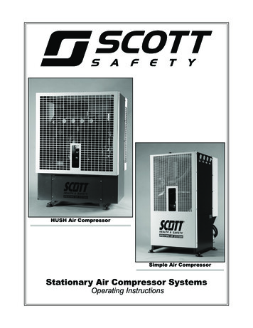
Installation Guide for WABCO 85MMReplacement Cylinder HeadWARNING: To prevent serious eye injury, always wear eye protection when performing vehicle maintenance.Remove all pressure from the air system before you disconnect any component.Park the vehicle on a level surface and block wheels to prevent the vehicle from rolling1)4)1)1)1)Items included in this Kit:Cylinder Head AssemblyTorque-to-Yield Head BoltsInlet Valve (a)Head Gasket (b)Sliding Leaf ValveCylinder Head RemovalBe sure not to damage crankcase since it is not to bereplaced.1. Set parking brake and block wheels.2. Drain air pressure from system.3. Drain engine coolant system and cylinder headof the compressor.4. Use cleaning solvent to remove dirt and oilfrom the exterior of the compressor.5. Remove air and coolant lines from compressor.6. Remove the four ½” hex head bolts that attachthe head to the cylinder block (figure 1)7. Remove cylinder head and head gasket.8. Use a cleaning solvent to clean the top of thecrankcase.The piston bore must be kept clean of debris. Place a clean towelover the bore in order to keep clean.
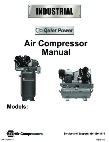
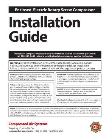
Cylinder Head Installation1. Flip head upside down as shown inFigure 22. Coat the sliding leaf valve (A) lightlywith engine oil. This will help hold itin place.3. Install the sliding leaf valve. Align thetwo holes of the sliding leaf valvewith the two pins on bottom ofhead as shown in figure 2.4. Install inlet valve (B). Coat lightlywith engine oil. Align valve with thelarge holes and the alignmentsleeves as shown in Figure 2.5. Notice the notch for the unloaderpiston guide pin.6. Install cylinder head gasket (C).Make sure all holes betweencylinder head gasket and inlet valveare aligned as shown in Figure 2.Figure 2Attaching assembled head to crankcase1. Carefully flip the assembled head over, paying close attention not to dislodge sliding leafvalve, inlet valve and head gasket.2. Position the head on top of the crankcase. Make sure the notched pins of the head alignwithin the recesses of the crankcase, as shown in Fiqure 3.3. Screw in four hex bolts in by hand, being careful to not damage the gaskets.4. Tighten in sequence 1‐2‐3‐4 (Figure 4) to 18.5 to /‐2.5ib‐ft. Then apply 90 15 /‐5 rotation . Use angular gauge to check rotation.5. Connect all air and coolant lines leading to the air compressor. Tighten per vehiclespecifications.
Figure 4Figure 3Testing1. With the parking brake engaged and wheels blocked, bleed down the vehicle air system reservoirgauges (pump brakes several times) to approximately 85psi.2. With engine running at full governed speed (no load or air accessories being used), the compressorshould reach cutout pressure and unload.If the compressor does not reach governor cutout pressure,check for leaks in the system.If the compressor fails to unload, make sure governoris working properlyAir System Leak Test1. Park vehicle on level surface. Engage parking brake. Disconnect any attached or towed vehicle. Blocktires. Leave engine on.2. Release parking brakes.3. With compressor in pumping mode, engine at idle and service brakes applied , air gauge must staybetween 80‐90 psi or rise slightly.4. If pressure is not maintained, check for air leaks in the system. This can be done by listening or thespraying a water and soap solution on the air system.Helpful Hints:1. This is a good time to check inlet and discharge lines for any restrictions.2. If cylinder walls show signs of scoring and pumping excess oil, change out thecompressor
9111539202Water Port3/4” – 16STORDischarge PortM27- 2.0STOR9111539212Water PortM18 – 1.5STORDischarge PortM27 – 2.0STOR9111539312Water Port3/8” NPTDischarge Port½” NPTWABCO Heads (Cummins & MACK USAApplications)All of the 85MM Wabco Heads listed are the same design with theexception of the water and discharge port sizeThere are two versions of the valve body for the 85MM.(Cummins & MACK)The Mack has a drain outlet.The Mack valve body can also be used for the Cummins, if you blockoff the outlet with a pipe plug.
Part #854323(with head bolts)85MMHead Kit854323WO(without head bolts)picturedHEAD KITSPart #754323(withhead bolts)75MMHead Kit754323WO(without head bolts)pictured
9111535100XCUMMINSISXSS31885MM18.7 CFMOEM X9111535107XUSES HEAD #91115392129111535200XCUMMINSL, M, NSERIESSS31885MM18.7 CFMOEM #’S35581633104324RX4059825RX3103403RXUSES HEAD #91115392029111535200X9111535207X
9111535300XCUMMINSISCSS31885MM18.7 33782USES HEAD SB SERIESSS31885MM18.7 CFMOEM #’S39368103969104USES HEAD #91115392029111535330X9111535337X
9111545000XCUMMINSB SERIESSS25075MM15.2 CFMOEM #’S394446039488423976362Uses Head ication of a Wabco Part Number911 154Product Type500Version0ConditionEvery Wabco part has a 10 digit Part NumberThe number is grouped in a 3.3.3.1 formationUsing this code, the following can be identified0247Condition:New Complete Assembly (Black ID plate fixed to part)Repair Kit or Sub AssemblyIndividual PartExchange Unit (Reman.Red ID plate fixed to part)
CumminsInformationOE PartNumber911 154 502 239368083969102911 154 502 0Model75mmCFMBoreSize75mm36 Tooth Gear911 154 502 73936808397636639665173936808RX911 154 515 0911 154 515 749462944946294RX911 154 510 085mm911 154 510 0911 153 003 0Additional Information11 tooth spline11 tooth spline.11 tooth spline911 153 003 7911 153 011 0911 153 011 73969114911 154 513 0911 154 513 73976362494629339690983976362RX911 154 650 64946293906 130 14 15412 352 002 0911 153 520 03558163405982542 Tooth Gear13 Tooth Spline75mm36 Tooth Gear34 Tooth GearSS31818.785mmSS31818.785mm911 153 520 7911 153 510 0911 153 510 7368190436819023103413495275838 Tooth Gear11 Tooth Spline
CumminsInformationOE PartNumber911 154 500 m18.785mmAdditional Information911 154 500 7911 153 530 03944524394452639445253966522SS31842 Tooth Gear394884649337834933782Can be 11 or 13 tooth spline.13 tooth is standard.9111539202X REMAN HEAD911 153 530 7911 153 533 736 Tooth gear 30mm gear bolt4933780911 153 004 7911 153 010 73969110RX911 153 010 0369611085mmRear Spline 11T Right Hand911 153 938 0911 515 008 73103414RX911 515 008 0911 154 001 03949096SS63675mm36 tooth gear (diagonal teeth)Top oil feed.911 154 001 7411 145 003 7411 145 005 0411 145 005 7911 154 511 0884 596 030 011 tooth spline
CumminsInformation911 154 516 0911 154 503 0OE PartNumber911 153 013 0911 153 013 74933745911 154 509 0911 153 547 7ModelCFMBoreSizeAdditional Information11 tooth 63613911 153 531 03948849X394884985mm911 154 520 0494629049462900075mm911 153 014 0911 153 014 7493355949335590085mmIntake is turned toward the drive end of thecompressor (front flange)11 Tooth Spline
WABCO SYSTEM SAVER 318 MACK E-TECH & ASET ENGINESMACK E-TECH & ASET ENGINESFront of A/C is mounted to engine2 Versions Non Thru Drive Thru DriveRuns accessories (i.e.hydraulic powerSteering pump, etc) Single CylinderWABCO SYSTEM SAVER 636 TWIN CYLINDER forMACK E-TECH ENGINESMACK E-TECH & ASET ENGINESFront of A/C is mounted to engine1 Version Non Thru DriveDoes not have the hookup for any accessories(i.e. power steering pump, etc) Twin CylindersCFM 18.7CFM 37.4Flange Mount Coupling drivenInlet air, lub & coolant supplied from engine Compression is controlled by the PneumaticPressure Signal from the governor Pressure Relief ValveFlange Mount Coupling DrivenInlet Air, Coolant, & Lube supplied fromEngine Compression is controlled by the PneumaticPressure Signal from the governor Integrated Pressure Relief ValveConsists of 2 Sub Assemblies¾ 1)Cylinder HeadMounts to Crankcase2 Water Ports, Inlet, Discharge &Unloader Valving, Integral Relief Valve¾ 2)CrankCaseContains: Cylinder Block, Crankshaft,Piston & Bearings, Governor Port &Connecting Rod**Can Remove Cylinder Head without removingWhole Air Compressor**Use Compressor Mounting Gasket #590GB2159if you are replacing the whole air compressor,instead of just the cylinder headCylinder Head 4 Retention Bolts 1 Sliding Leaf ValveConsists of 2 Sub Assemblies¾ 1)Cylinder HeadMounts to Crankcase, 2 Water Ports, 1Inlet port (Inlet port for hose connection),Inlet, Discharge & Unloader Valving, andIntegral Relief Valve¾ 2)CrankcaseContains: Governor Port & ConnectingRods, Cylinder Block, Piston, Bearings &Crankshaft**Can remove Cylinder Head without removingWhole Air Compressor**Use Compressor Mounting Gasket #590GB2159 ifyou are replacing the whole air compressor, instead ofjust the cylinder headCylinder Head 6 Retention Bolts 2 Sliding Leaf Valves
WABCO MACK E-TECH AND ASET ENGINESFront ViewExtended Flange with GearMounts to EngineWithout PlateModels ShownSS318CFM18.7Size85MM11 ToothSpline(thru drive only)With 111530567X9111530560XThru-Drive(spline shown)NonThru-Drive(solid rear crankcase)Back View
9111535400XTHRU-DRIVETHRU-DRIVE(for power steeringpump, etc)MACKTHRU DRIVESS31885MM18.7 CFMEXTENDED FLANGEW/GEAR11 TOOTH SPLINEEXCHANGE EM #303GB5129MUSES HEAD#9111539312THRU-DRIVEWith Removable rear plate can beused to replace Non Thru Drive.
9111535410XNON THRU-DRIVENONTHRU-DRIVEMACKNON THRU-DRIVESS31885MM18.7 CFMEXTENDED FLANGEW/GEARSAME AS9111535400XEXCEPT NO THRUDRIVEUSES HEAD#9111539312EXCHANGE 30550X9111530557XCan be Replaced by the9111535400X Thru-Drive(rear plate attached)
9115150080XMACK ASET TWIN CYLINDEREXCHANGE #9115150080X9115150087X9111530567XMACK ASET 85MM18.7CFMEXCHANGE #9111530567X9111530560X9111535410X9111535417X
MACKInformation911 153 540 0S 911 153 540 0911 153 540 7OE PartNumber303GB5129M303GB5129M303GB5129M911 153 541 al Information85mmHead KitPart Number 85MMHEADKITcan be replaced by the 911 153 540 0 throughdrive with removable rear plate911 153 541 7Crosses to:911 153 056 0911 153 056 7Can ReplaceWith:911 153 055 0911 153 055 7S911 153 055 0911 153 055 0S911 153 055 7911 153 055 7S911 153 540 0911 153 540 0S911 153 540 7911 153 540 7911 153 056 0S911 153 056 0911 153 056 7S911 153 056 7Crosses to:911 153 541 0911 153 541 7Can ReplaceWith:911 153 055 0911 153 055 T2303GB4225T2303GB4225T2303GB4225T218.7Mack ASET85mmThru Drive With Removeable rear plate canbe used to replace non thru drive 911 153 541 0Mack ASET85mm
MACKInformation911 515 008 0S911 515 008 0911 515 008 7S911 515 008 7OE Part Number912 142 000 0S912 142 000 0912 142 000 7S912 142 000 7912 542 001 0S912 542 001 0912 542 001 7S912 542 001 7Replacement:CFMApplicationMack ASETBoreSizeAdditional InformationTwin CylinderMack HDEP2D774376Mack HDEPTwin Cylinder2 press in inspection caps bottom,1 inspection cap rear.912 512 926 2
VOLVO INFORMATION412 704 008 0S412 704 008 0412 704 008 7S412 704 008 7412 704 008 0Replacement for412 704 001 0OE Part Number20701801Additional InformationTwin Cylinder85000396912 112 000 0S912 112 000 0912 112 000 7S912 112 000 7Volvo HDEP912 512 004 0S912 512 004 0912 512 004 7S912 512 004 7911 505 150 0911 505 150 7ApplicationVolvo D12Twin 2007X
WABCO Air CompressorParts & InformationBepco, Inc2475 S Stratford RoadWinston Salem, NC 27103800-735-1154 fax 336-768-3756
2. Drain air pressure from system. 3. Drain engine coolant system and cylinder head of the compressor. 4. Use cleaning solvent to remove dirt and oil from the exterior of the compressor. 5. Remove air and coolant lines from compressor. 6. Remove the four ½" hex head bolts that attach the head to the cylinder block (figure 1) 7.