Transcription
Bendix ACom Diagnostic Software 6.9User Guide 1996-2016 Bendix Commercial Vehicle Systems LLC, a member of the Knorr-Bremse Group.All Rights Reserved
INDEXGeneral Information . . . . . . . . . . . . . . . . . . . . . . . . . . . . . . . . . 3RP1210 Adapters . . . . . . . . . . . . . . . . . . . . . . . . . . . . . . . . . . 4PC Hardware Requirements . . . . . . . . . . . . . . . . . . . . . . . . . . . . . 4Technical Assistance . . . . . . . . . . . . . . . . . . . . . . . . . . . . . . . . . 4Installing Bendix ACom Diagnostic Software . . . . . . . . . . . . . . . . . . . 5Using Bendix ACom Diagnostic Software . . . . . . . . . . . . . . . . . . . . . . 5Bendix ACom Diagnostic Windows 6.9 ECU Status Screen . . . . . . . . . . . . . 6Diagnostic Trouble Code Screen. . . . . . . . . . . . . . . . . . . . . . . . . . . 7Wheel Speed Sensor Screen . . . . . . . . . . . . . . . . . . . . . . . . . . . . 7Configuration Screen . . . . . . . . . . . . . . . . . . . . . . . . . . . . . . . . 8Bendix Trailer Roll Stability Program (TRSP) Screen . . . . . . . . . . . . . . . . 8Auxiliary Design Language (ADL) . . . . . . . . . . . . . . . . . . . . . . . . . . 8Pressures Screen . . . . . . . . . . . . . . . . . . . . . . . . . . . . . . . . . . 9Sensor Calibration . . . . . . . . . . . . . . . . . . . . . . . . . . . . . . . . . 10Component Test Screen . . . . . . . . . . . . . . . . . . . . . . . . . . . . . . 10Modulators . . . . . . . . . . . . . . . . . . . . . . . . . . . . . . . . . . . . . 11Bendix Trailer Roll Stability Program (TRSP) (If Equipped) . . . . . . . . . . . . 11Miscellaneous . . . . . . . . . . . . . . . . . . . . . . . . . . . . . . . . . . . 11Installation Test. . . . . . . . . . . . . . . . . . . . . . . . . . . . . . . . . . . 12Customize . . . . . . . . . . . . . . . . . . . . . . . . . . . . . . . . . . . . . 12Installation Test Requirements . . . . . . . . . . . . . . . . . . . . . . . . . . . 13ECU Information . . . . . . . . . . . . . . . . . . . . . . . . . . . . . . . . . . 13Bendix ACom Diagnostic Software 6.9 Adaptive Cruise w/Braking (ACB) . . . . . 16ACB Data Log . . . . . . . . . . . . . . . . . . . . . . . . . . . . . . . . . . . 18Bendix ACom Diagnostic Software FLC20 Camera Snapshot . . . . . . . . . . . 192
The User accepts that no expectation of reliabilityof any given version of Bendix ACom software tobe able to retrieve any specific version of data isgiven. It is the User’s responsibility to verify thesuitability of any data retrieved by the software.General InformationBendix ACom diagnostics will provide the technicianwith the capability to configure and troubleshoot Bendixcomponents.This application will support the following Bendix products: Bendix EC-60 electronic controller Bendix EC-80 electronic controller Bendix Wingman active cruise with braking Bendix VORAD VS400 radar system Bendix FLC20 camera system Bendix SafetyDirect Processor (SDP) Bendix SmarTire Tire Pressure MonitoringSystem (TPMS) Bendix Trailer-Link System Bendix Tractor Lift Axle ABS module Bendix TABS-6 Trailer ABS module Bendix TABS-6 Advanced trailer ABS module Bendix TABS-6 Advanced MC trailer ABSmodule Bendix TABS-6 Advanced MV trailer ABSmodule Bendix EC-30 electronic controller Bendix EC-17 electronic controller Bendix EC-30T electronic controller Bendix MC-30 electronic controller Bendix A-18 electronic controller Bendix Gen 4 (U1x) electronic controller Bendix Gen 5 (U12 and U16) electronic controllerDepending on the product type and version, BendixElectronic Control Units (ECUs) may store datarelated to troubleshooting, diagnostics, serviceneeds, vehicle system operating status and vehicleoperator inputs. No personally identifying data(e.g. name, gender or age) is recorded. Bendix willnot access stored ECU data or share it with othersexcept: with the consent of the vehicle owner; inresponse to an official request by law enforcementor other governmental agency; as part of Bendix’sdefense of litigation; or, as otherwise required bylaw. Data that Bendix receives may also be usedfor research purposes or made available to othersfor research purposes, where a need is shown andthe data is not linked to a specific vehicle or owner.Bendix ECUs are not designed to store datafor purposes of accident reconstruction andBendix ACom Diagnostic Software is notintended to retrieve data for purposes of accidentreconstruction. Bendix makes no representationsas to the accuracy of data retrieved and interpretedfrom ECUs for purposes of accident reconstruction.Bendix does not offer accident reconstructionservices or interpretation of stored data. BendixECUs are not protected from fire, loss of power,impact, damage or other conditions that may besustained in a crash situation and may cause datato be unavailable or irretrievable.The ACOM, BENDIX, EC-60, EC-80, ESP, FLC20,GEN 4, GEN 5, MC-30, SAFETYDIRECT, SMART ATC,SMARTCRUISE, SMARTIRE, TABS-6, TRAILERLINK, VORAD, WINGMAN, WS-24, XVISION, YAS-60and YAS-70X trademarks are licensed to or owned byBendix Commercial Vehicle Systems LLC. Windows,Windows NT, Windows 2000, Windows Vista andWindows XP are either registered trademarks ortrademarks of Microsoft Corporation in the UnitedStates and/or other countries.Any referencesin this document to CATERPILLAR, CUMMINS,DEARBORN, NEXIQ NOREGON, VOLVO, and anyother company or trademark are solely for identificationpurposes. The trademarks are the property of theirrespective companies and are not affiliated with orendorsing Bendix Commercial Vehicle Systems LLC.Bendix Commercial Vehicle Systems LLC does notrepresent any parts shown as products manufacturedor remanufactured by the companies so named herein.This guide, as well as the software described in it,is furnished under license and may only be used orcopied in accordance with the terms of the license.Please contact the Bendix Tech Team for a copy ofsuch license.PLEASE NOTE: The information provided in thismanual is for informational purposes only and issubject to change without notice and should not beconstrued as a guarantee by Bendix CommercialVehicle Systems LLC (Bendix). Bendix assumesno responsibility or liability for any errors orinaccuracies that may appear in this publicationnor within the Bendix ACom Diagnostic Softwareitself. The User is using the software “as-is”,“where-is” with no warranty implied or otherwise.At no time shall Bendix be liable to the user for anydirect, special, indirect, consequential, liquidated,punitive, or progressive damages relative to theuse of the software hereunder.The User is responsible to ensure that the correctversion of the Bendix ACom diagnostic software hasbeen selected for the controller being connected.3
RP1210 AdaptersPC Hardware RequirementsThe Bendix ACom Diagnostic software relieson RP1210 compliant hardware adapters forcommunication.A list of the recommendedadapters is shown below.Bendix ACom diagnostic software will run onWindows Vista , Windows 7, Windows 8 and Windows10 operating systems. Below are the minimumrequirements for running the application.NOTE: Bendix ACom diagnostic software willremain in the demo mode unless there is at leastone RP1210 driver installed on the computer.What follows is a list of supported hardware adaptersfor the software. 1 Gigahertz (GHz) or faster 32-bit (x86) or 64-bit(x64) processor 2 GB RAM 1 GB free disk space Microsoft Internet Explorer 8 Before using this software, verify that the driver(.dll) for the adapter to be used for communicationsis already loaded on the computer and is the latestversion available from the adapter manufacturer. Caterpillar CAT Communications Adapter III Adobe Acrobat (latest version recommended) USB Communication port VGA standard graphics adapter with a resolution of800 x 600 (minimum), 1024 x 768 recommendedWindows compatible keyboard and mouse Cummins Inline 5 Cummins Inline 6NOTE: Windows 95, 98 and XP operating systemsare not supported.The content displayed on a Bendix ACom diagnosticsoftware screen depends on: the Electronic ControlUnit (ECU) selected on the Start page; and also on thefeatures enabled on the ECU. Certain features/optionsof the software may not be visible, since they do notapply to the ECU being inspected. Dearborn DPA4 Dearborn DPA5 Dearborn Netbridge Dearborn PLC TestCon (may be available in a kitwith DPA4 ) Nexiq USB-Link Nexiq Bluetooth USB-Link Nexiq USB-Link2 Nexiq Bluetooth USB-Link2 Nexiq WVL2 Nexiq PLC Converter Nexiq Universal J560 PLC Adapter Noregon JPRO DLA Noregon JPRO DLA PLC Noregon Trailer Diagnostics Adapter Volvo Vocom 88890020 Volvo Vocom 88890300For extended details on the features of a particularBendix ACom diagnostic software screen, select theHelp button located on that screen.Technical AssistanceFor any questions regarding setup or operationof ACom diagnostics please contact Bendix at1-800-AIR-BRAKE (1-800-247-2725). See the Bendixwebsite, www.bendix.com for periodic softwareupdates.Licensing InformationBENDIX ACom diagnostic software requires an enduser license agreement, including user consent,prior to installing the software on the user’scomputer.Note: Adapters that interface using serial or parallelports to the laptop are no longer supported.4
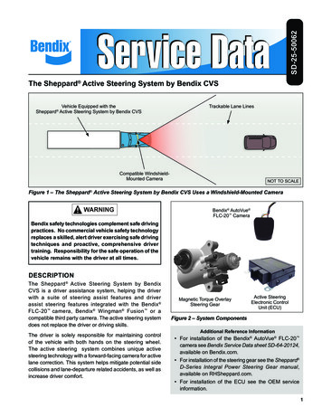
Installing Bendix ACom Diagnostic SoftwareUsing Bendix ACom Diagnostic SoftwareWhen installing Bendix ACom diagnostic softwareit is recommended that all other programs be closed.Bendix ACom diagnostic software will be installed usinga setup wizard, during which the technician will need toacknowledge various questions for the installation tocontinue.An icon will be placed on the desktop. Double click theicon or select the Bendix ACom diagnostic softwareapplication from the Bendix install directory or Programgroup to launch the program. A Starter screen willappear.The starter screen has various features:1. The desired communication adapter can beselected by clicking the icon depicting a computerand tractor/trailer. (See the arrow shown in Figure4.) Selecting this icon opens up the driver selectionfor the RP1210 adapter. Check the box next to theadapter you will use, then press the green checkbox to confirm.Figure 1The Bendix ACom diagnostic software is installed tothe default location of C:\Bendix\ACom Diagnostics.During installation of Bendix ACom diagnostic software6.9, several applications will be installed and severalinstallation windows will appear. If there are any olderversions of Bendix ACom diagnostic software on thecomputer, Bendix ACom diagnostic software will uninstall the older versions.Figure 3Bendix ACom diagnostic software 5.12 will also beinstalled with the Bendix ACom Diagnostic Software6.9.After a period of time, a pop-up box will be displayedindicating that the installation was successful.Figure 42. The entry screen allows the technician to Start withthe Electronic Control Unit (ECU). If the technicianknows which ECU they are diagnosing, select itfrom the list on the Starter screen and press theStart with ECU button. See Figure 4.Figure 2Next the Setup wizard will report that the setup iscompleting and allow the technician to launch theBendix ACom diagnostic software tool.5
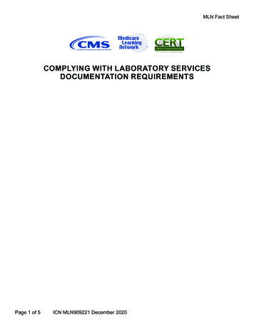
3. Alternatively, the program will detect the ElectronicControl Unit (ECU). The screen will indicate whichBendix ECU was found and the technician canselect Launch to start Bendix ACom diagnosticsoftware.Bendix TABS-6 Advanced MV trailer ABSmoduleAdditionally, Bendix ACom diagnostic software 5.12 isincluded on the Bendix ACom 6.9 CD and will supportthe following: Bendix TABS-6 trailer ABS module Bendix EC-30 electronic controller Bendix EC-17 electronic controller Bendix EC-30T electronic controller Bendix MC-30 electronic controller Bendix A-18 electronic controller Bendix Gen 4 (U1x) electronic controller Bendix Gen 5 (U12 and U16) electronic controllerIf you have any questions about the operation of BendixACom diagnostic software 5.12, open the Bendix AComdiagnostic software 5.12 User Guide PDF available onthe Bendix web site (www.bendix.com).Figure 54. Any ECU can be displayed in the DEMO modeby pressing the Start in demo mode button. TheDemo mode allows the technician to investigatethe program’s features without communicating withan actual ECU.Bendix ACom DiagnosticWindows 6.9 ECU Status ScreenRefer to the Service Data sheet for the system beingdiagnosed for all cautions and warnings; certainsystem changes (e.g. sensor position changes) requireapproval from the Bendix Engineering team.Bendix ACom diagnostic software opens, by default,to the ECU status screen. This screen provides thetechnician with a snap-shot of the ECU. In the SystemData field, the following information is displayed: systemname, part number, serial number, software version,ABS configuration, odometer, whether Bendix TrailerRoll Stability Program (TRSP) and Auxiliary DesignLanguage (ADL) program is enabled or disabled.Additionally, in the Status field, the voltage and thenumber of active Diagnostic Trouble Codes (DTCs) ifany are displayed.Figure 6The following ECU controllers are supported byBendix ACom diagnostic software 6.9 on the BendixACom 6.9 CD: Bendix EC-60 electronic controller Bendix EC-80 electronic controller Bendix Wingman active cruise with braking Bendix VORAD VS400 radar system Bendix FLC20 camera system Bendix Safety Direct Processor (SDP) Bendix SmarTire Tire Pressure MonitoringSystem (TPMS) Bendix Trailer-Link System Bendix Tractor Lift Axle ABS module Bendix TABS-6 Advanced trailer ABS module Bendix TABS-6 Advanced MC trailer ABSmoduleFigure 7From the ECU Status screen the technician can openthe DTC screen by either double clicking on the ABSlamp or selecting the DTC button. The technician canalso open the wheel speed sensor or configurationscreens by selecting the appropriate button.6
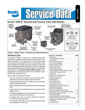
Control Buttons for Electronic Control Unit (ECU)Status: The DTC button will open the DTC screen The Clear button will clear the information fromtab and a pop-up box will confirm that the ECUhas processed the request. Click the pop-up toacknowledge. The Report button opens a screen for thetechnician to generate a DTC report, additionally,the technician can select to save, email or printDTC reports. The Help button opens help page for the DTCscreen.Diagnostic Trouble Code (DTC) Screen The Close button closes the DTC screen.The DTC screen provides the technician with active,inactive and event history information. For the activeDTC information, the screen is divided into three panes.The first pane displays the active DTCs, the secondpane displays troubleshooting/repair informationcorresponding to the active DTC; and the third panedisplays the connector with pin-out so the techniciancan troubleshoot the active DTC. Additionally, a countof the number of occurrences of the DTC, and odometerreadings of the first and last occurrence of the DTC andthe current odometer reading are provided.Wheel Speed Sensor Screen The Wheels button will open the wheel speedsensor screen The Config button will open the configuration screen The Help button will open the Help page for ECUStatus The Close button will close the screenThe wheel speed sensor screen allows the technicianto spin the wheels and record the sensor output.Additionally, there is a sensor air gap field whichindicates the speed when the sensor starts registeringspeed. A lower air gap speed value (e.g. 3 to 4) indicatesa properly adjusted wheel speed sensor. An air gapspeed value higher than 5 indicates that the wheelspeed sensor needs to be adjusted by installing thesensor closer to the tone ring eliminating the distancebetween the sensor and tone ring.Figure 10Control Buttons for Graph: The Start button will start the data collection.Figure 8The event history screen displays information for:configuration change events; the history of clearedevents; end of line test complete, and more. The Stop button will stop the data collection. The Rewind button will rewind the data. The Forward button will forward the data. The graph display can be a line graph (default), abar graph, or 3D-style graph.Control Buttons for Wheel Speed: The Open File button will open an existing wheelspeed file. The Load File button will load an existing wheelspeed file. The Help button will open the Help page. The Close button will close the screen.Figure 9Control Buttons for DTC Screen: The Service button will open the Service Data sheetfor the ECU. The Repair button will open the repair file for wheelspeed sensors only. The Read button will read the information from theECU.7
Configuration ScreenBendix Trailer Roll StabilityProgram (TRSP) ScreenThe Configuration screen provides the technician withthe following information: ABS configuration, Load andSensor, TRSP (if equipped), Auxiliary Design Language(ADL), AUX I/O and Broadcast options.Note: TRSP screen will be available if the ECU supportsTRSP. The TRSP window allows the technician tocheck if TRSP is enabled, the TRSP module position,ECU orientation, and the TRSP parameters.ABS ConfigurationABS Configuration provides the technician with thenumber of sensors and modulators the ElectronicControl Unit (ECU) is currently configured to expect.Vehicle Data provides the technician with vehicletype and the number of axles. Odometer displaysthe odometer, trip and service odometer. WheelParameters displays the stored tire size and tone ringsize and single or double tire.Figure 13Auxiliary Design Language (ADL)The ADL screen allows the technician to verify thatthe ECU has auxiliary design language program forspecific operation. This screen is read only.Figure 11Load and Sensor ConfigurationThe Sensors field provides the technician withinformation on how the external load sensor (ifequipped) is configured. The Bogie Load field showsthe expected weight for the rear axle empty and fullyloaded. The Miscellaneous field shows the wheel trackwidth and number of lift axles. The Lateral AccelerationSensing field provides whether the sensing type isinternal or external (if equipped). The Load Sensingfield displays the sensing type (internal or external)and the expected air bag pressures - empty and fullyloaded.Figure 14AUX I/OThe AUX I/O screen allows the technician to see howthe ECU’s auxiliary inputs and outputs are configured.This screen is read only.Figure 15BroadcastThe Broadcast screen allows the technician to seewhich J2497 and J1939 messages are (or are not)enabled.Figure 128
Control Buttons for Graph: The Start button will start the data collection The Stop button will stop the data collection The Rewind button will rewind the data The Forward button will forward the data The graph display can be a line graph (default), abar graph, or 3D-styleControl Buttons for Pressure Screen: The Open file button will open an existing pressurefileFigure 16 The Load file button will load an existing pressurefileThe Save button will save the configuration file ofthe ECU The Help button will open the Help page The Close button will close the screen The Help button will open the HELP page The Close button will close the screenBendix Trailer Roll Stability Program (TRSP)SensorsNOTE: The TRSP sensors will only be available if theECU supports TRSP. The TRSP sensors allow thetechnician to monitor the lateral acceleration sensor,axle load and installation angle data.Control Buttons for Configuration Screens: The Modify button will open the change screen Pressures ScreenThe Pressures screen allows the technician to viewand record pressures supplied by the trailer ABSsystem. The table below describes which pressuresare reported by supported Electronic Control Units(ECUs). The pressures screen allows the technician toapply the brakes and monitor the pressures.Trailer ECU ge(MV) MultiChannel(MC)Supply- P1NoNoYesYesControl- o viewDelivery- P21Delivery- P22Air Bag- P42Figure 18NoNoYesYesYesNoYesNoControl Buttons for Graph: The Start button will start the data collection The Stop button will stop the data collection The Rewind button will rewind the data The Forward button will forward the data The graph display can be a line graph (default), abar graph or 3D-style graphControl Buttons for TRSP Sensors: The Open File button will open an existing TRSPfileFigure 179 The Load File button will load an existing TRSP file The Help button will open the Help page The Close button will close the screen
Sensor CalibrationComponent Test ScreenThe Sensor Calibration page allows the LateralAcceleration Sensor (LAS) to be calibrated. The trailerneeds to be on a level surface for the calibration.Press “Start” to begin the calibration process, use the“Yes, No, or Cancel” choices to answer any questions.Bendix ACom diagnostic software can be used torecalibrate the lateral acceleration sensor, clear anyDTCs and display the actual sensor value.The Component Test screen allows the technicianto test various components of the system such as:wheel speed sensors; modulators; pressure sensors;switches; and the Bendix Trailer Roll Stability Program(TRSP) system. The Component Test screen alsoallows the technician to perform system tests such as:battery voltage; ABS indicator lamp; Aux I/O; and axleload.Note: Before performing the component test, makesure the vehicle is parked on a level and flat groundwith the wheels chocked.Figure 20The Component test screen supports various tests;each tab will be populated with the tests which aresupported by the Electronic Control Unit (ECU). Thetabs are Sensors, Modulators, Pressures, TRSP system(if equipped) and Miscellaneous. Select the appropriatetab and the left side of the screen will display a list ofavailable tests. Upon selecting the test, the right sideof the screen will show what the technician must dobefore the test can run.Figure 19Control Buttons for TRSP Sensors: The Start button starts the calibration The Yes button is used to acknowledge that thetechnician is in agreement with the question asked The No button is used when the techniciandisagrees with the question asked The Cancel button stops the calibration The Close button closes the calibration windowFigure 21Control Buttons for Component Test: The Start/Next button will start the test and/or movethe technician to the next step of the test10 The Stop button will stop the test The Service Data button will open the service datasheet The Help button will open Help The Close button will close the screen
Bendix Trailer Roll StabilityProgram (TRSP) (If Equipped)ModulatorsThis test allows the technician to check the modulators.The test displays the number of modulators currentlyconfigured in the Electronic Control Unit (ECU). Toselect the modulator to check, simply press the Start/Next button to start the test. Follow the instructions onthe screen. The program will prompt the technicianby asking “Did the modulator respond correctly?” Thetechnician should respond by selecting the green checkmark button indicating “yes”, or the red circle with a linebutton indicating “no.”Note: TRSP will be available only if the ECU supportsTRSP. This test will allow the technician to checkthe TRSP sensor installation angle. To begin, thetechnician will need to select “installation angle”, thenpress the Start/Next button to begin the test. Follow theprompts to run the test. The program will prompt thetechnician by asking, “Did the ECU respond correctly?”The technician must then acknowledge if the test wassuccessful by selecting the green check mark indicating“yes”, or the red circle with a line indicating “no.”Figure 22Figure 24PressureThis test will allow the technician to test the variouspressure sensors supported by the ECU. PressStart/Next button to start the test and follow theinstructions. The program will ask the technician, “Didthe ECU respond correctly?” The technician needs toacknowledge if the test was successful by selecting thegreen check mark indicating “yes” or the red circle witha line indicating “no.”MiscellaneousThis test will allow the technician to evaluate the batteryvoltage, ABS indicator lamp, and AUX I/O functions.The function will display the tests available which aresupported by the ECU. The technician must selectwhich function(s) to check, then press the Start/Nextbutton to start the test. Follow the prompts to completethe evaluation. The program will prompt the technicianby asking, “Did the ECU respond correctly?” Thetechnician must acknowledge by selecting the greencheck mark indicating “yes”, or the red circle with a lineindicating “no.”Figure 23Figure 2511
Installation Test Save a report in TXT or HTML formatThe Installation Test is for OEMs to make end-of-lineverification tests on new vehicles. The test allowsthe technician to verify the proper installation of theElectronic Control Unit (ECU) and system components. Save a report using the Vehicle VIN as the filename Create a folder in which to save the report (theprogram will prompt to ask for a folder and filename)NOTE: In order for the Installation Test to run, thetechnician must first acknowledge the systemgenerated warning indicating that the vehicle must beparked on a level surface. Select to show wheel speeds in either MPH or RPM Select if you wish the test sequence to stop if theprevious test failed Select if the technician needs to confirm if theservice brake is applied during the modulator testAdditionally, the Bendix ACom diagnostic softwareInstallation Test provides a check of the ABScomponents with the help of technician input. Pleasenote that the Installation Test is intended as a toolto assist the quality control process at the vehiclemanufacturer. However, this test must not be reliedon as the sole validation check of proper brakesystem installation. The vehicle manufacturer mustensure appropriate process controls are in place inthe manufacturing process to completely validatethe vehicle brake system prior to vehicle shipment.Figure 27Control Buttons for Customize: The OK button is used to accept changesFigure 26CustomizeThe Customize screen allows the technician tocustomize some of the features in the installation test. The Cancel button is used to cancel (not accept)changesWarning: The tests conducted must match thefeatures of the vehicle being tested. With eachvehicle, it is important to confirm that the correctsets of features are being verified. Typically theBendix ACom diagnostic software will save thefeatures used on the previous test, so if the softwarewas used on a vehicle with different features duringits last use, the customized features must be reassessed and changed to match the new vehicle. The Up button moves highlighted test up the list The Down button moves highlighted test down thelistIf there are any active Diagnostic Trouble Codes(DTCs) on the ECU, the installation will not run, and thetechnician will be notified by a message. Active DTCsmust be corrected and cleared before the InstallationTest can be performed.To complete any necessary changes, simply click inthe box next to a desired test name — a check markwill appear — to request that the test be performed.Similarly, you may uncheck boxes to skip those tests.Mandatory tests are displayed on the screen in gray,optional tests appear in black.Figure 28You may use the screen to: Re-arrange the order of the tests12
Installation Test RequirementsECU InformationThe chart below indicates which tests are available foran Electronic Control Unit (ECU). If there is a YES nextto the test name, that specific test is required in order tocomplete the Installation Test. If there is a “NO” shownfor a test, that test is not required in order to completethe Installation Test. If there is an “N/A” shown for atest, this indicates that the ECU does not support thatspecific test. As a result, the test will not appear in theInstallation Test list. For the wheel speed sensors, atleast one of the two sensor tests is required – indicatedby the word “ONE” in the chart. Bendix recommendsthat the full sensor test be run, although the simplesensor test is an acceptable option.ECU information test is a mandatory test, it must alwaysbe run. It provides the technician with informationabout how the ECU is configured.All the tests in the table below refer to Bendix TABS-6Advanced modules.Installation TestBendix TABS-6 Advanced (ADV) AAxle LoadYESYESNONOS-C Sensoror SimpleONEONEONEONES-D Sensoror SimpleONEONEONEONES-E Sensoror SimpleN/AONEN/AONES-F Sensoror oltageNONONONOABSIndicatorLampNONONONOAUX I/ONONONONOScratchPadYESYESYESYESFigure 29Installation ConfigurationThe Installation Configuration field displays a graphic –and specifics – about the expected configuration. Thetechnician must verify that the components have beeninstalled as shown.Figure 30Additionally, tests in gray text must be performed andtests in black text are optional.13
Axle Load TestThe Axle Load Test is mandatory for the Bendix TABS-6 Advanced (ADV) Electronic Control Unit(ECU), but not when inspecting the Bendix TABS-6 Multi-Voltage (MV) ECU. This test displays the detectedweight on the rear axle in pounds.Figure 33Installation Angle TestThe Installation Angle Test displays the vertical angleof the mounted ECU. The vertical angle must be within 5 degrees of vertical.NOTE: The installation angle test will only be availableif the ECU supports Bendix Trailer Roll StabilityProgram (TRSP).Figure 31Battery Voltage TestThe Battery Voltage Test checks the voltage measuredat the ECU, with the modulators de-energized,energized and de-energized. The voltage operatingrange is 8.0 VDC to 32.0 VDC for Bendix
6 3. Alternatively, the program will detect the Electronic Control Unit (ECU). The screen will indicate which Bendix ECU was found and the technician can select Launch to start Bendix ACom diagnostic software. Figure 5