Transcription
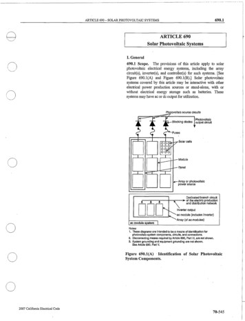
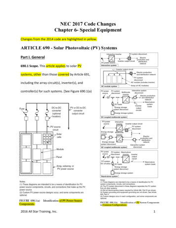
NEC 2017 Code ChangesChapter 6- Special EquipmentChanges from the 2014 code are highlighted in yellow.ARTICLE 690 - Solar Photovoltaic (PV) SystemsPart I. General690.1 Scope. This article applies to solar PVsystems, other than those covered by Article 691,including the array circuit(s), inverter(s), andcontroller(s) for such systems. [See Figure 690.1(a)2016 All Star Training, Inc.1
and Figure 690.1(b).] The systems covered by this article may be interactive with otherelectrical power production sources or stand-alone or both, and may or may not be connectedto energy storage systems such as batteries. These PV systems may have ac or dc output forutilization.Informational Note: Article 691 covers the installation of large scale PV electric supply stations.690.2 Definitions.Alternating-Current (ac) Module (Alternating-Current Photovoltaic Module). A complete,environmentally protected unit consisting of solar cells, optics, inverter, and other components,exclusive of tracker, designed to generate ac power when exposed to sunlight.Array. A mechanically integrated assembly of module(s) or panel(s) with a support structureand foundation, tracker, and other components, as required, to form a dc or ac powerproducing unit. center tap.Bipolar Photovoltaic Array. A dc PV array that has two outputs, each having opposite polarityto a common reference point or center tap.DC-to-DC Converter. A device installed in the PV source circuit or PV output circuit that canprovide an output dc voltage and current at a higher or lower value than the input dc voltageand current.DC-to-DC Converter Output Circuit. Circuit conductors between the dc-to-dc converter sourcecircuit(s) and the inverter or dc utilization equipment.2016 All Star Training, Inc.2
DC-to-DC Converter Source Circuit. Circuits between dc-to-dc converters and from dc-to-dcconverters to the common connection point(s) of the dc system.Direct-Current (dc) Combiner. A device used in the PV source and PV output circuits to combinetwo or more dc circuit inputs and provide one dc circuit output.Diversion Charge Controller. Equipment that regulates the charging process of a battery bydiverting power from energy storage to direct-current or alternating-current loads or to aninterconnected utility service.Electrical Production and Distribution Network. A power production, distribution, andutilization system, such as a utility system and connected loads, that is external to and notcontrolled by the PV power system.Functional Grounded PV System. A PV system that has an electrical reference to ground that isnot solidly grounded.Informational Note: A functional grounded PV system is often connected to ground through afuse, circuit breaker, resistance device, non-isolated grounded ac circuit, or electronic meansthat is part of a listed ground-fault protection system. Conductors in these systems that arenormally at ground potential may have voltage to ground during fault conditions.Generating Capacity. The sum of parallel-connected inverter maximum continuous outputpower at 40 C in kilowatts.Interactive System. A PV system that operates in parallel with and may deliver power to anelectrical production and distribution network.2016 All Star Training, Inc.3
Interactive Inverter Output Circuit. The conductors between the interactive inverter and theservice equipment or another electrical power production and distribution network.Inverter. Equipment that is used to change voltage level or waveform, or both, of electricalenergy. Commonly, an inverter [also known as a power conditioning unit (PCU) or powerconversion system (PCS)] is a device that changes dc input to an ac output. Inverters may alsofunction as battery chargers that use alternating current from another source and convert itinto direct current for charging batteries.Inverter Input Circuit. Conductors connected to the dc input of an inverter.Inverter Output Circuit. Conductors connected to the ac output of an inverter.Module. A complete, environmentally protected unit consisting of solar cells, optics, and othercomponents, exclusive of tracker, designed to generate dc power when exposed to sunlight.Monopole Subarray. A PV subarray that has two conductors in the output circuit, one positive( ) and one negative ( ). Two monopole PV subarrays are used to form a bipolar PV array.Multimode Inverter. Equipment having the capabilities of both the interactive inverter and thestand-alone inverter.Panel. A collection of modules mechanically fastened together, wired, and designed to providea field-installable unit.Photovoltaic Output Circuit. Circuit conductors between the PV source circuit(s) and theinverter or dc utilization equipment.Photovoltaic Power Source. An array or aggregate of arrays that generates dc power at systemvoltage and current.2016 All Star Training, Inc.4
Photovoltaic Source Circuit. Circuits between modules and from modules to the commonconnection point(s) of the dc system.Photovoltaic System DC Circuit. Any dc conductor supplied by a PV power source, including PVsource circuits, PV output circuits, dc-to-dc converter source circuits, or dc-to-dc converteroutput circuits.Solar Cell. The basic PV device that generates electricity when exposed to light.Stand-Alone System. A solar PV system that supplies power independently of an electricalproduction and distribution network.Subarray. An electrical subset of a PV array.690.4 General Requirements.(A) Photovoltaic Systems. Photovoltaic systems shall be permitted to supply a building or otherstructure in addition to any other electrical supply system(s).(B) Equipment. Inverters, motor generators, PV modules, PV panels, ac modules, dc combiners,dc-to-dc converters, and charge controllers intended for use in PV systems shall be listed orfield labeled for the PV application.(C) Qualified Personnel. The installation of equipment and all associated wiring andinterconnections shall be performed only by qualified persons.Informational Note: See Article 100 for the definition of qualified person.2016 All Star Training, Inc.5
(D) Multiple PV Systems. Multiple PV systems shall be permitted to be installed in or on a singlebuilding or structure. Where the PV systems are remotely located from each other, a directoryin accordance with 705.10 shall be provided at each PV system disconnecting means.(E) Locations Not Permitted. PV system equipment and disconnecting means shall not beinstalled in bathrooms.690.6 Alternating-Current (ac) Modules.(A) Photovoltaic Source Circuits. The requirements of Article 690 pertaining to PV sourcecircuits shall not apply to ac modules. The PV source circuit, conductors, and inverters shall beconsidered as internal wiring of an ac module.(B) Inverter Output Circuit. The output of an ac module shall be considered an inverter outputcircuit.Part II. Circuit Requirements690.7 Maximum Voltage. The maximum voltage of PV system dc circuits shall be the highestvoltage between any two circuit conductors or any conductor and ground. PV system dc circuitson or in one- and two-family dwellings shall be permitted to have a maximum voltage of 600volts or less. PV system dc circuits on or in other types of buildings shall be permitted to have amaximum voltage of 1000 volts or less. Where not located on or in buildings, listed dc PVequipment, rated at a maximum voltage of 1500 volts or less, shall not be required to complywith Parts II and III of Article 490.2016 All Star Training, Inc.6
(A) Photovoltaic Source and Output Circuits. In a dc PV source circuit or output circuit, themaximum PV system voltage for that circuit shall be calculated in accordance with one of thefollowing methods:Informational Note: One source for lowest-expected, ambient temperature design data forvarious locations is the chapter titled Extreme Annual Mean Minimum Design Dry BulbTemperature found in the ASHRAE Handbook Fundamentals, 2013. These temperature data canbe used to calculate maximum voltage.(1) Instructions in listing or labeling of the module: The sum of the PV module–ratedopen circuit voltage of the series connected modules corrected for the lowest expectedambient temperature using the open-circuit voltage temperature coefficients inaccordance with the instructions included in the listing or labeling of the module(2) Crystalline and multi-crystallinemodules: For crystalline and multicrystalline silicon modules, the sum ofthe PV module–rated open-circuitvoltageoftheseriesconnectedmodules corrected for the lowestexpected ambient temperature usingthe correction factor provided in Table690.7(A)2016 All Star Training, Inc.7
(3) PV systems of 100 kW or larger: For PV systems with a generating capacity of 100 kWor greater, a documented and stamped PV system design, using an industry standardmethod and provided by a licensed professional electrical engineer, shall be permitted.Informational Note: One industry standard method for calculating maximum voltage of a PVsystem is published by Sandia National Laboratories, reference SAND 2004-3535, PhotovoltaicArray Performance Model. The maximum voltage shall be used to determine the voltage ratingof conductors, cables, disconnects, overcurrent devices, and other equipment.(B) DC-to-DC Converter Source and Output Circuits. In a dcto- dc converter source and outputcircuit, the maximum voltage shall be calculated in accordance with 690.7(B)(1) or (B)(2).(1) Single DC-to-DC Converter. For circuits connected to the output of a single dc-to-dcconverter, the maximum voltage shall be the maximum rated voltage output of the dcto-dc converter.(2) Two or More Series Connected DC-to-DC Converters. For circuits connected to theoutput of two or more series connected dc-to-dc converters, the maximum voltage shallbe determined in accordance with the instructions included in the listing or labeling ofthe dc-to-dc converter. If these instructions do not state the rated voltage of seriesconnected dc-to-dc converters, the maximum voltage shall be the sum of the maximumrated voltage output of the dc-to-dc converters in series.(C) Bipolar Source and Output Circuits. For 2-wire dc circuits connected to bipolar PV arrays,the maximum voltage shall be the highest voltage between the 2-wire circuit conductors where2016 All Star Training, Inc.8
one conductor of the 2-wire circuit is connected to the functional ground reference (centertap). To prevent overvoltage in the event of a ground-fault or arc-fault, the array shall beisolated from the ground reference and isolated into two 2-wire circuits.690.8 Circuit Sizing and Current.(A) Calculation of Maximum Circuit Current. The maximum current for the specific circuit shallbe calculated in accordance with 690.8(A)(1) through (A)(6).Informational Note: Where the requirements of 690.8(A)(1) and (B)(1) are both applied, theresulting multiplication factor is 156 percent.(1) Photovoltaic Source Circuit Currents. The maximum current shall be calculated byone of the following methods:(1) The sum of parallel-connected PV module–rated short circuit currentsmultiplied by 125 percent(2) For PV systems with a generating capacity of 100 kW or greater, adocumented and stamped PV system design, using an industry standard methodand provided by a licensed professional electrical engineer, shall be permitted.The calculated maximum current value shall be based on the highest 3-hourcurrent average resulting from the simulated local irradiance on the PV arrayaccounting for elevation and orientation. The current value used by this methodshall not be less than 70 percent of the value calculated using 690.8(A)(1)(1).2016 All Star Training, Inc.9
Informational Note: One industry standard method for calculating maximum current of a PVsystem is available from Sandia National Laboratories, reference SAND 2004-3535, PhotovoltaicArray Performance Model. This model is used by the System Advisor Model simulation programprovided by the National Renewable Energy Laboratory.(2) Photovoltaic Output Circuit Currents. The maximum current shall be the sum ofparallel source circuit maximum currents as calculated in 690.8(A)(1).(3) Inverter Output Circuit Current. The maximum current shall be the invertercontinuous output current rating.(4) Stand-Alone Inverter Input Circuit Current. The maximum current shall be thestand-alone continuous inverter input current rating when the inverter is producingrated power at the lowest input voltage.(5) DC-to-DC Converter Source Circuit Current. The maximum current shall be the dc-todc converter continuous output current rating.(6) DC-to-DC Converter Output Circuit Current. The maximum current shall be the sumof parallel connected dc-to-dc converter source circuit currents as calculated in690.8(A)(5).(B) Conductor Ampacity. PV system currents shall be considered to be continuous. Circuitconductors shall be sized to carry not less than the larger of 690.8(B)(1) or (B)(2) or whereprotected by a listed adjustable electronic overcurrent protective device in accordance690.9(B)(3), not less than the current in 690.8(B)(3).2016 All Star Training, Inc.10
(1) Before Application of Adjustment and Correction Factors. One hundred twenty-fivepercent of the maximum currents calculated in 690.8(A) before the application ofadjustment and correction factors.Exception: Circuits containing an assembly, together with its overcurrent device(s), that is listedfor continuous operation at 100 percent of its rating shall be permitted to be used at 100percent of its rating.(2) After Application of Adjustment and Correction Factors. The maximum currentscalculated in 690.8(A) after the application of adjustment and correction factors.(3) Adjustable Electronic Overcurrent Protective Device. The rating or setting of anadjustable electronic overcurrent protective device installed in accordance with 240.6.(C) Systems with Multiple Direct-Current Voltages. For a PV power source that has multipleoutput circuit voltages and employs a common-return conductor, the ampacity of the commonreturn conductor shall not be less than the sum of the ampere ratings of the overcurrentdevices of the individual output circuits.(D) Sizing of Module Interconnection Conductors. Where a single overcurrent device is used toprotect a set of two or more parallel-connected module circuits, the ampacity of each of themodule interconnection conductors shall not be less than the sum of the rating of the singleovercurrent device plus 125 percent of the short-circuit current from the other parallelconnected modules.2016 All Star Training, Inc.11
690.9 Overcurrent Protection.(A) Circuits and Equipment. PV system dc circuit and inverter output conductors andequipment shall be protected against overcurrent. Overcurrent protective devices shall not berequired for circuits with sufficient ampacity for the highest available current. Circuitsconnected to current limited supplies (e.g., PV modules, dc-to-dc converters, interactiveinverter output circuits) and also connected to sources having higher current availability (e.g.,parallel strings of modules, utility power) shall be protected at the higher current sourceconnection.Exception: An overcurrent device shall not be required for PV modules or PV source circuit or dcto-dc converters source circuit conductors sized in accordance with 690.8(B) where one of thefollowing applies:(1) There are no external sources such as parallel-connected source circuits, batteries, orbackfeed from inverters.(2) The short-circuit currents from all sources do not exceed the ampacity of theconductors and the maximum overcurrent protective device size rating specified for thePV module or dc to-dc converter.Informational Note: Photovoltaic system dc circuits are current limited circuits that only needovercurrent protection when connected in parallel to higher current sources. The overcurrentdevice is often installed at the higher current source end of the circuit.2016 All Star Training, Inc.12
(B) Overcurrent Device Ratings. Overcurrent devices used in PV system dc circuits shall belisted for use in PV systems. Overcurrent devices, where required, shall be rated in accordancewith one of the following:(1) Not less than 125 percent of the maximum currents calculated in 690.8(A).(2) An assembly, together with its overcurrent device(s), that is listed for continuousoperation at 100 percent of its rating shall be permitted to be used at 100 percent of itsrating.(3) Adjustable electronic overcurrent protective devices rated or set in accordance with240.6.Informational Note: Some electronic overcurrent protective devices prevent backfeed current.(C) Photovoltaic Source and Output Circuits. A single overcurrent protective device, whererequired, shall be permitted to protect the PV modules and conductors of each source circuit orthe conductors of each output circuit. Where single overcurrent protection devices are used toprotect PV source or output circuits, all overcurrent devices shall be placed in the same polarityfor all circuits within a PV system. The overcurrent devices shall be accessible but shall not berequired to be readily accessible.Informational Note: Due to improved ground-fault protection required in PV systems by690.41(B), a single overcurrent protective device in either the positive or negative conductors2016 All Star Training, Inc.13
of a PV system in combination with this ground-fault protection provides adequate overcurrentprotection.(D) Power Transformers. Overcurrent protection for a transformer with a source(s) on eachside shall be provided in accordance with 450.3 by considering first one side of the transformer,then the other side of the transformer, as the primary.Exception: A power transformer with a current rating on the side connected toward theinteractive inverter output, not less than the rated continuous output current of the inverter,shall be permitted without overcurrent protection from the inverter.690.10 Stand-Alone Systems. The wiring system connected to a stand-alone system shall beinstalled in accordance with 710.15.690.11 Arc-Fault Circuit Protection (Direct Current). Photovoltaic systems operating at 80 voltsdc or greater between any two conductors shall be protected by a listed PV arc-fault circuitinterrupter or other system components listed to provide equivalent protection. The systemshall detect and interrupt arcing faults resulting from a failure in the intended continuity of aconductor, connection, module, or other system component in the PV system dc circuits.Informational Note: Annex A includes the reference for the Photovoltaic DC Arc-Fault CircuitProtection product standard.2016 All Star Training, Inc.14
Exception: For PV systems not installed on or in buildings, PV output circuits and dc-to-dcconverter output circuits that are direct buried, installed in metallic raceways, or installed inenclosed metallic cable trays are permitted without arc-fault circuit protection. Detachedstructures whose sole purpose is to house PV system equipment shall not be consideredbuildings according to this exception.690.12 Rapid Shutdown of PV Systems on Buildings. PV system circuits installed on or inbuildings shall include a rapid shutdown function to reduce shock hazard for emergencyresponders in accordance with 690.12(A) through (D).Exception: Ground mounted PV system circuits that enter buildings, of which the sole purpose isto house PV system equipment, shall not be required to comply with 690.12.(A) Controlled Conductors. Requirements for controlled conductors shall apply to PV circuitssupplied by the PV system.(B) Controlled Limits. The use of the term array boundary in this section is defined as 305 mm(1 ft.) from the array in all directions. Controlled conductors outside the array boundary shallcomply with 690.12(B)(1) and inside the array boundary shall comply with 690.12(B)(2).(1) Outside the Array Boundary. Controlled conductors located outside the boundary ormore than 1 m (3 ft.) from the point of entry inside a building shall be limited to notmore than 30 volts within 30 seconds of rapid shutdown initiation. Voltage shall bemeasured between any two conductors and between any conductor and ground.2016 All Star Training, Inc.15
(2) Inside the Array Boundary. The PV system shall comply with one of the following:(1) The PV array shall be listed or field labeled as a rapid shutdown PV array.Such a PV array shall be installed and used in accordance with the instructionsincluded with the rapid shutdown PV array listing or field labeling.Informational Note: A listed or field labeled rapid shutdown PV array is evaluated as anassembly or system as defined in the installation instructions to reduce but not eliminate risk ofelectric shock hazard within a damaged PV array during fire-fighting procedures. These rapidshutdown PV arrays are designed to reduce shock hazards by methods such as limiting accessto energized components, reducing the voltage difference between energized components,limiting the electric current that might flow in an electrical circuit involving personnel withincreased resistance of the conductive circuit, or by a combination of such methods.(2) Controlled conductors located inside the boundary or not more than 1 m (3ft.) from the point of penetration of the surface of the building shall be limited tonot more than 80 volts within 30 seconds of rapid shutdown initiation. Voltageshall be measured between any two conductors and between any conductor andground.(3) PV arrays with no exposed wiring methods, no exposed conductive parts, andinstalled more than 2.5 m (8 ft.) from exposed grounded conductive parts orground shall not be required to comply with 690.12(B)(2). The requirement of690.12(B)(2) shall become effective January 1, 2019.2016 All Star Training, Inc.16
(C) Initiation Device. The initiation device(s) shall initiate the rapid shutdown function of the PVsystem. The device “off” position shall indicate that the rapid shutdown function has beeninitiated for all PV systems connected to that device. For one-family and two-family dwellings,an initiation device(s) shall be located at a readily accessible location outside the building.The rapid shutdown initiation device(s) shall consist of at least one of the following:(1) Service disconnecting means(2) PV system disconnecting means(3) Readily accessible switch that plainly indicates whether it is in the “off” or “on”positionInformational Note: One example of why an initiation device that complies with 690.12(C)(3)would be used is where a PV system is connected to an optional standby system that remainsenergized upon loss of utility voltage. Where multiple PV systems are installed with rapidshutdown functions on a single service, the initiation device(s) shall consist of not more than sixswitches or six sets of circuit breakers, or a combination of not more than six switches and setsof circuit breakers, mounted in a single enclosure, or in a group of separate enclosures. Theseinitiation device(s) shall initiate the rapid shutdown of all PV systems with rapid shutdownfunctions on that service. Where auxiliary initiation devices are installed, these auxiliary devicesshall control all PV systems with rapid shutdown functions on that service.2016 All Star Training, Inc.17
(D) Equipment. Equipment that performs the rapid shutdown functions, other than initiationdevices such as listed disconnect switches, circuit breakers, or control switches, shall be listedfor providing rapid shutdown protection.Informational Note: Inverter input circuit conductors often remain energized for up to 5minutes with inverters not listed for rapid shutdown.Part III. Disconnecting Means690.13 Photovoltaic System Disconnecting Means. Means shall be provided to disconnect thePV system from all wiring systems including power systems, energy storage systems, andutilization equipment and its associated premises wiring.(A) Location. The PV system disconnecting means shall be installed at a readily accessiblelocation.Informational Note: PV systems installed in accordance with 690.12 address the concernsrelated to energized conductors entering a building.(B) Marking. Each PV system disconnecting means shall plainly indicate whether in the open(off) or closed (on) position and be permanently marked “PV SYSTEM DISCONNECT” orequivalent. Additional markings shall be permitted based upon the specific systemconfiguration. For PV system disconnecting means where the line and load terminals may be2016 All Star Training, Inc.18
energized in the open position, the device shall be marked with the following words orequivalent:WARNINGELECTRIC SHOCK HAZARDTERMINALS ON THE LINE AND LOADSIDES MAY BEENERGIZED IN THE OPEN POSITIONThe warning sign(s) or label(s) shall comply with 110.21(B).(C) Suitable for Use. If the PV system is connected to the supply side of the servicedisconnecting means as permitted in 230.82(6), the PV system disconnecting means shall belisted as suitable for use as service equipment.(D) Maximum Number of Disconnects. Each PV system disconnecting means shall consist of notmore than six switches or six sets of circuit breakers, or a combination of not more than sixswitches and sets of circuit breakers, mounted in a single enclosure, or in a group of separateenclosures. A single PV system disconnecting means shall be permitted for the combined acoutput of one or more inverters or ac modules in an interactive system.Informational Note: This requirement does not limit the number of PV systems connected to aservice as permitted in 690.4(D). This requirement allows up to six disconnecting means todisconnect a single PV system. For PV systems where all power is converted through interactiveinverters, a dedicated circuit breaker, in 705.12(B)(1), is an example of a single PV systemdisconnecting means.2016 All Star Training, Inc.19
(E) Ratings. The PV system disconnecting means shall have ratings sufficient for the maximumcircuit current available short-circuit current, and voltage that is available at the terminals ofthe PV system disconnect.(F) Type of Disconnect.(1) Simultaneous Disconnection. The PV system disconnecting means shallsimultaneously disconnect the PV system conductors of the circuit from all conductorsof other wiring systems. The PV system disconnecting means shall be an externallyoperable general-use switch or circuit breaker, or other approved means. A dc PVsystem disconnecting means shall be marked for use in PV systems or be suitable forbackfeed operation.(2) Devices Marked “Line” and “Load.” Devices marked with “line” and “load” shall notbe permitted for backfeed or reverse current.(3) DC-Rated Enclosed Switches, Open-Type Switches, and Low-Voltage Power CircuitBreakers. DC-rated, enclosed switches, open-type switches, and low-voltage powercircuit breakers shall be permitted for backfeed operation.2016 All Star Training, Inc.20
(A) Photovoltaic Source Circuits. The requirements of Article 690 pertaining to PV source circuits shall not apply to ac modules. The PV source circuit, conductors, and inverters shall be considered as internal wiring of an ac module. (B) Inverter Output Circuit. The output of an ac module shall be considered an inverter output circuit. Part II.