Transcription
Strength of MaterialLab ManualRoll No:Name:Year: Semester:
Strength of Material2018-19Lab ManualCERTIFICATECertified that this file is submitted byShri/Ku.Roll No. a student of year of the courseas a part of PRACTICAL/ORAL asprescribed by the Rashtrasant Tukadoji Maharaj Nagpur University for the subjectStrength of Materials in the laboratory of SOM LAB during the academic yearand that I have instructed him/her for the said work,from time to time and I found him/her to be satisfactory progressive.And that I have accessed the said work and I am satisfied that the same is up to thatstandard envisaged for the course.Date:-PROF. MOHD ATIFSignature & Nameof Subject TeacherSignature & Nameof HOD1
Strength of MaterialLab Manual2018-19Anjuman College of Engineering and TechnologyVision To be a centre of excellence for developing quality technocrats with moral and socialethics, to face the global challenges for the sustainable development of society.Mission To create conducive academic culture for learning and identifying career goals. To provide quality technical education, research opportunities and imbibeentrepreneurship skills contributing to the socio-economic growth of the Nation. To inculcate values and skills, that will empower our students towards developmentthrough technology.Vision and Mission of the DepartmentVision: To be the centre of excellence for developing quality Civil Engineers with moral andsocial ethics to face global challenges for the sustainable development of society.Mission: To create conductive academic culture for learning and identifying career goals. To impart quality technical education along with research opportunities. To impart knowledge and generate entrepreneurship skills contributing to socioeconomic growth of the nation. To inculcate values and skills, that will empower our students, towards Nationaldevelopment through technology, to preserve nature and its resources.PROF. MOHD ATIF2
Strength of MaterialLab Manual2018-19Program Educational Objectives (PEOs) Apply technical knowledge to find solution to the challenges in various areas and todevelop independent thinking in the field of Civil Engineering. Have analyze, design, technical and soft skills, for solving problem Civil Engineering. Inculcate morality professionals and ethical sense and self confidence. Take higher education or lifelong learning and contribute in research anddevelopment throughout life.Program Specific Outcomes (PSOs) An ability to plan, analyze, design and execute low cost housing and constructionworks. An ability to provide the basic facilities with optimal utilization of resources to meetthe societal needs.PROF. MOHD ATIF3
Strength of Material2018-19Lab ManualPROGRAM: CEDEGREE: B.ECOURSE: STRENGTH OF MATERIALSEMESTER: IIICOURSE CODE: BECVE302PCOURSE TYPE: REGULARCOURSE AREA/DOMAIN:CONTACT HOURS: 2 hours/Week.CORRESPONDING LAB COURSE CODE :LAB COURSE NAME : Strength of MaterialCREDITS: 25 MarksCOURSE PRE-REQUISITES:C.CODECOURSE NAMEDESCRIPTIONSEMBECVE302PIIILAB COURSE OBJECTIVES: This course explains the debate for each object oriented design principle. Draw a high level class diagram in UML for each pattern. Classify how the different components of the pattern collaborate with each other. List the consequences of each pattern to the overall software quality of a system.COURSE OUTCOMES: Design PatternsAfter completion of this course the students will be able SNODESCRIPTIONBLOOM’S TAXONOMYLEVELCO.1Understand the concept and application of various types of strain gauges.LEVEL 2CO.2Evaluate different engineering properties of engineering materials byperforming different test on it.LEVEL 5CO.3LEVEL 4Understand the physical insight into the behaviour materials andstructural elements, including distribution of stresses and strains,deformations and failure modesCO.4Develop individual and group reports: present objectives, describe testprocedures and results, synthesize and discuss the test results, presentconclusions.PROF. MOHD ATIFLEVEL 34
Strength of MaterialLab Manual2018-19Lab Instructions: Students should come to the lab on time unless prior permission is obtained from thesupervisor. As per department policy, a grace period of 10 minutes will be given to latestudents. Student arriving after 10 minutes of the starting time will be considered absent.Hence, he/she will automatically receive “zero” mark for the lab report. Students will be divided in to groups (preferably 2/3 students in a group). Each groupwill be given a handout. This will serve as a guide for them throughout the experiment. All students must have to submit the lab report just after the entrance and before the classstart. Lab reports have to be submitted serially. Students have to complete the sample calculations and graphs in class and take sign fromthe course teacher. (In some experiment which require more times, should be completedas possible in class time.) Students should be very careful about any test. They should conduct the tests by takingmaximum care of the equipment during test. Thoroughly clean your laboratory work space at the end of the laboratory session. Keep work area neat and free of any unnecessary objects. Never block access to exits or emergency equipment. Food and drink, open or closed, should never be brought into the laboratory. Know the location of all the exits in the laboratory and building at the time ofemergency.PROF. MOHD ATIF5
Strength of Material2018-19Lab ManualContinuous Assessment PracticalExpNo123NAME OF EXPERIMENTStudy The Universal Testing Machine(U.T.M.)Perform the Tensile test on a metalusing Universal Testing Machine(U.T.M.)To determine the compressivestrength of brickPageNo5Study various types of Strain Gauges.22-266Perform Hardness test on Mild Steel.27-287Perform Impact strength of steel. (ByIzod test)29-30PROF. MOHD ATIFRemarkment18-1920-219Sign14-17Perform Shear Test on Metals.To determine the Stiffness of theSpring and Modulus of Rigidity of theSpring wire.To determine the stiffness & modulusof rigidity of the spring wireCommence8-1348Date of31-3334-376
Strength of Material2018-19Lab ManualCONTENTSExpNoNAME OF EXPERIMENT1Study The Universal Testing Machine (U.T.M.)23Perform the Tensile test on a metal usingUniversal Testing Machine (U.T.M.)To determine the compressive strength of brick4Perform Shear Test on Metals.5Study various types of Strain Gauges.6Perform Hardness test on Mild Steel.7Perform Impact strength of steel. (By Izod test)8To determine the Stiffness of the Spring andModulus of Rigidity of the Spring wire.9To determine the stiffness & modulus of rigidityof the spring wirePROF. MOHD ATIFDate ofSubmissionSignRemark7
Strength of MaterialLab Manual2018-19EXPERIMENT NO – 1AIM: - Study of Universal Testing Machine (U.T.M.)OBJECT: - To Study the various component parts of the Universal Testing Machine(U.T.M.) & test procedures of various practical’s to be performed.APPARATUS: - Universal Testing Machine with all attachment i.e. shears test attachment,bending attachment, tension grips, compression test attachment etc.DIAGRAM:-PROF. MOHD ATIF8
Strength of MaterialLab Manual2018-19THEORY : - The Universal Testing Machine consists of two units.1) Loading unit, 2) Control panel.LOADING UNIT:It consists of main hydraulic cylinder with robust base inside. The piston whichmoves up and down. The chain driven by electric motor which is fitted on lefthand side. The screw column maintained in the base can be rotated using abovearrangement of chain. Each column passes through the main nut which is fittedin the lower cross head.The lower table connected to main piston through a ball & the ball seat isjoined to ensure axial loading. There is a connection between lower table andupper head assembly that moves up and down with main piston. Themeasurement of this assembly is carried out by number of bearings whichslides over the columns.The test specimen each fixed in the job is known as ‘Jack Job’. To fix up thespecimen tightly, the movement of jack job is achieved helically by handle.CONTROL PANEL:It consists of oil tank having a hydraulic oil level sight glass for checking the oillevel. The pump is displacement type piston pump having free plungers thoseensure for continuation of high pressure. The pump is fixed to the tank frombottom. The suction & delivery valve are fitted to the pump near tank Electricmotor driven the pump is mounted on four studs which is fitted on the right sideof the tank. There is an arrangement for loosing or tightening of the valve. Thefour valves on control panel control the oil stroke in the hydraulic system. Theloading system works as described below.The return valve is close, oil delivered by the pump through the flow controlvalves to the cylinder & the piston goes up. Pressure starts developing &either the specimen breaks or the load having maximum value is controlled withthe base dynameters consisting in a cylinder in which the piston reciprocates.The switches have upper and lower push at the control panel for the downward& upward movement of the movable head. The on & off switch provided on thecontrol panel & the pilot lamp shows the transmission of main supply.METHOD OF TESTING:Initial Adjustment: - before testing adjust the pendulum with respect tocapacity of the test i.e. 8 Tones; 10 Tones; 20 Tones; 40 Tones etc.For ex: - A specimen of 6 tones capacity gives more accurate result of 10 Tonescapacity range instead of 20 Tones capacity range. These ranges ofcapacity are adjusted on the dial with the help of range selector knob.The control weights of the pendulum are adjusted correctly.PROF. MOHD ATIF9
Strength of MaterialLab Manual2018-19The ink should be inserted in pen holder of recording paper around the drum &the testing process is started depending upon the types of test as mentionedbelow.TENSION TEST:Select the proper job and complete upper and lower check adjustment. Applysome Greece to the tapered surface of specimen or groove. Then operate theupper cross head grip operation handle & grip the upper end of test specimenfully in to the groove. Keep the lower left valve in fully close position. Open theright valve & close it after lower table is slightly lifted. Adjust the lower pointsto zero with the help of adjusting knob. This is necessary to remove the deadweight of the lower table. Then lock the jobs in this position by operating jobworking handle. Then open the left control valve. The printer on dial gauge atwhich the specimen breaks slightly return back & corresponding load is knownas breaking load & maximum load is known as the ultimate load.COMPRESSION TEST:Fix upper and lower pressure plates to the upper stationary head & lower tablerespectively. Place the specimen on the lower plate in order to grip. Then adjustzero by lifting the lower table. Then perform the test in the same manner asdescribed in tension test.FLEXURAL OR BENDING TEST:Keep the bending table on the lower table in such a way that the central positionof the bending table is fixed in the central location value of the lower table. Thebending supports are adjusted to required distance.Stuffers at the back of the bending table at different positions. Then place thespecimen on bending table & apply the load by bending attachment at the upperstationary head. Then perform the test in the same manner as described intension test.BRINELL HARDNESS TEST:Place the specimen on the lower table & lift it up slightly. Adjust the zero fixedvalue at the bottom side of the lower cross head. Increase the load slowlyultimate load value is obtained. Then release the load slowly with left controlvalve. Get the impression of a suitable value of five to ten millimeter on thespecimen & measure the diameter of the impression correctly by microscope &calculate Brinell hardness.SHEAR TEST:Place the shear test attachment on the lower table, this attachment consists ofcutter. The specimen is inserted in roles of shear test attachment & lift thelower table so that the zero is adjusted, then apply the load such that thePROF. MOHD ATIF10
Strength of MaterialLab Manual2018-19specimen breaks in two or three pieces. If the specimen breaks in two piecesthen it will be in angle shear, & if it breaks in three pieces then it will be indouble shear.STUDY OF EXTENSOMETER:This instrument is an attachment to Universal / Tensile Testing Machines. Thismeasures the elongation of a test place on load for the set gauge length. Theleast count of measurement being 0.01 mm, and maximum elongationmeasurement up to 3 mm. This elongation measurement helps in finding out theproof stress at the required percentage elongation.WORKING OF THE INSTRUMENT:-The required gauge length(between30to 120 ) is set by adjusting the upper knife edges ( 3 ) A scale ( 2 ) is providedfor this purpose . Hold the specimen in the upper and lower jaws of Tensile /Universal Testing Machine. Position the extensometer on the specimen.Position upper clamp (4) To press upper knife edges on the specimen. Theextensometer will be now fixed to the specimen by spring pressure. Set zero onboth the dial gauges by zero adjust screws (7 ). Start loading the specimen andtake the reading of load on the machine at required elongation or the elongationat required load. Force setter accuracies mean of both the dial gauge ( 8)readings should be taken as elongation. It is very important to note & follow thepractice of removing the extensometer from the specimen before the specimenbreaks otherwise the instrument will be totally damaged. As a safety, whiletesting the instrument may be kept hanging from a fixed support by a slightlyloose thread.TECHNICAL DATA:Measuring Range: 0 – 3 mm.Least Count: 0. 01 mm.Gauge Length adjustable from: 30 – 120 mmSpecimen Size: 1 to 20mm Round or Flats up to 20 x 20 mm.PROF. MOHD ATIF11
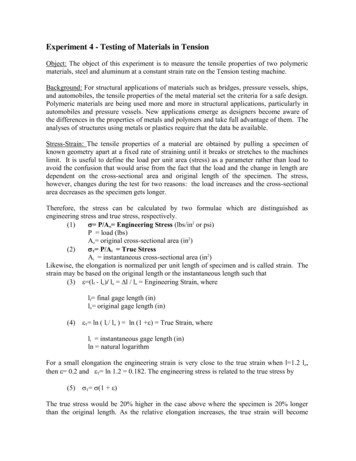
Strength of MaterialLab Manual2018-19A) Stress-strain graph of Mild SteelPROF. MOHD ATIF12
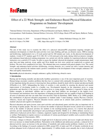
Strength of Material2018-19Lab ManualB) Stress-strain graphs of different materials. Curve A shows a brittle material. This material is also strongbecause there is little strain for a high stress. The fracture of abrittle material is sudden and catastrophic, with little or no plasticdeformation. Brittle materials crack under tension and the undercompression. Curve B is a strong material which is not ductile. Steel wires stretchvery little, and break suddenly. There can be a lot of elastic strainenergy in a steel wire under tension and it will “whiplash” if itbreaks. The ends are razor sharp and such a failure is verydangerous indeed. Curve C is a ductile material Curve D is a plastic material. Notice a very large strain for a smallstress. The material will not go back to its original length.PROF. MOHD ATIF13
Strength of MaterialLab Manual2018-19EXPERIMENT NO. – 02AIM: -To Perform the tensile test on a metal.OBJECT: - To conduct a tensile test on a mild steel specimen and determine the(i)Limit of proportionality(ii) Elastic limit(iii) Yield strength(IV) Ultimate strength(v)Young’s modulus of elasticity(VI) Percentage elongation(VII) Percentage reduction in area.APPARATUS: (i)Universal Testing Machine (UTM)(ii)Mild steel specimens(iii) Graph paper(iv) Scale(v)Vernier CaliperDIAGRAM:- PROF. MOHD ATIF14
Strength of MaterialLab Manual2018-19THEORY:-The tensile test is most applied one, of all mechanical tests. In thistest ends of test piece are fixed into grips connected to a straining device andto a load measuring device. If the applied load is small enough, thedeformation of any solid body is entirely elastic. An elastically deformedsolid will return to its original from as soon as load is removed. However, ifthe load is too large, the material can be deformed permanently. The initialpart of the tension curve which is recoverable immediately after unloading istermed. As elastic and the rest of the curve which represents the manner inwhich solid undergoes plastic deformation is termed plastic. The stress belowwhich the deformations essentially entirely elastic is known as the yieldstrength of material. In some material the onset of plastic deformation isdenoted by a sudden drop in load indicating both an upper and a lower yieldpoint. However, some materials do not exhibit a sharp yield point. Duringplastic deformation, at larger extensions strain hardening cannot compensatefor the decrease in section and thus the load passes through a maximum andthen begins to decrease. This stage the “ultimate strength”’ which is definedas the ratio of the load on the specimen to original cross-sectional area,reaches a maximum value. Further loading will eventually cause ‘neck’formation and rupture.PROCEDURE:1) Measure the original length and diameter of the specimen. The length mayeither be length of gauge section which is marked on the specimen with apreset punch or the total length of the specimen.2. Insert the specimen into grips of the test machine and attach strainmeasuring device to it.3. Begin the load application and record load versus elongation data.4. Take readings more frequently as yield point is approached.5. Measure elongation values with the help of dividers and a ruler.6. Continue the test till Fracture occurs.7. By joining the two broken halves of the specimen together, measurethe final length and diameter of specimen.OBESERVATION:- A) Material:A) Original dimensionsLength -----------Diameter --------Area -------------B) Final Dimensions:Length ------------------Diameter ----------------Area -----------------------PROF. MOHD ATIF15
Strength of Material2018-19Lab ManualOBESERVATION TABLE:S.No Load(N)OriginalExtensionGauge length(mm)2Load (N/mm )Stress AreaIncrease in lengthStrain --------Original length12345To plot the stress strain curve and determine the following.(i) Limit pf proportionLoad at limit of Proportionaliy . N/mm2 Original area of cross-section(ii) Elastic limit (iii) Yield Strengthload at elastic limitOriginal area of c/s Yield loadOriginal area of c/s(iv) Ultimate Strength (v) Young’s Modulus, E (vi) Percentage Elongation (vii) Percentage reduction inareaN/mm2N/mm2Max Tensile loadOriginal area of c/sStress below proportionality limitCorresponding StrainN/mm2Final length (at fracture) – Original length X 100 (%)Original length Original area-area atfracture (final area)X 100 (%)Original area of c/sPROF. MOHD ATIF16
Strength of MaterialLab Manual2018-19RESULT:- i) Average Breaking Stress ii) Ultimate Stress iii) Average % Elongation PRECAUTION:1. If the strain measuring device is an extensometer it should beremoved before necking begins.2. Measure deflection on scale accurately & carefully.PROF. MOHD ATIF17
Strength of Material2018-19Lab ManualEXPERIMENT NO: - 03AIM: -TO DETERMINE THE COMPRESSIVE STRENGTH OF BRICKOBJECT: - The specimen brick is immersed in water for 24 hours.APPARATUS: Bricks, Oven Venire Caliper, Scale,Etc.FORMULA: Compressive Strength Max. Load at failure P N/mm2Area of brickATHEORY : - Bricks are used in construction of either load bearing walls or in portionwalls incase of frame structure. In bad bearing walls total weight fromslab and upper floor comes directly through brick and then it istransversed to the foundation. In case the bricks are loaded withcompressive nature of force on other hand in case of frame structurebricks are used only for construction of portion walls, layers comesdirectly on the lower layers or wall. In this case bricks are loaded withcompressive nature of force. Hence for safely measures before using thebricks in actual practice they have to be tested in laboratory for theircompressive strength.PROCEDURE: 1. Select some brick with uniform shape and size.2. Measure it’s all dimensions. (LXBXH)3. Now fill the frog of the brick with fine sand. And4. Place the brick on the lower platform of compression testing machineand lower the spindle till the upper motion of rams offered by aspecimen the oil pressure start increasing the pointer start returning tozero leaving the drug pointer that is maximum reading which can benoted down.PROF. MOHD ATIF18
Strength of Material2018-19Lab ManualOBSERVATION TABLE:S.No L X B XHAreaLoad /A(N/mm2Strength.Cm20102030405CALCULATION:- Compressive Strength RESULTMax. Load at failure----------------------------Loaded Area of brick: - The average compressive strength of new brick sample isfound to be . Kg/sq.cm.PRECAUTION: - 1) Measure the dimensions of Brick accurately.2) Specimen should be placed as for as possible inthe of lower plate.3) The range of the gauge fitted on the machine shouldnot be more than double the breaking load of specimenfor reliable results.PROF. MOHD ATIF19
Strength of MaterialLab Manual2018-19EXPERIMENT NO :- 04AIM: -To determine the Shear strength of steel.OBJECT: - To conduct shear test on specimens under double shear:APPARATUS: -i)Universal testing machine.ii)Shear test attachment.iii)Specimens.THEORY: - Place the shear test attachment on the lower table, this attachmentconsists of cutter. The specimen is inserted in shear test attachment & liftthe lower table so that the zero is adjusted, then apply the load such thatthe specimen breaks in two or three pieces. If the specimen breaks in twopieces then it will be in single shear & if it breaks in three pieces then itwill be in double shear.PROCEDURE:1. Insert the specimen in position and grip one end of the attachment inthe upper portion and one end in the lower portion.2. Switch on the main switch of universal testing machine machine.3. The drag indicator in contact with the main indicator.4. Select the suitable range of loads and space the corresponding weightin the pendulum and balance it if necessary with the help of smallbalancing weights.5. Operate (push) buttons for driving the motor to drive the pump.6. Gradually move the head control level in left-hand direction till thespecimen shears.7. Down the load at which the specimen shears.8. Stop the machine and remove the specimenRepeat the experiment with other specimens.OBESERVATION:Diameter of the Rod, D mmCross-section area of the Rod (in double shear) 2x (𝜋/4)𝐷2 mm2Load taken by the Specimen at the time of failure , W NStrength of rod against Shearing ƒx2x (𝜋/4)𝐷2ƒ W / 2x (𝜋/4)𝐷2 N/mm2PROF. MOHD ATIF20
Strength of MaterialLab Manual2018-19RESULT:The Shear strength of mild steel specimen is found to be N/mm2PRECAUTION :1 The measuring range should not be changed at any stageduring the test.2. The inner diameter of the hole in the shear stress attachmentshould be slightly greater than that of the specimen.3. Measure the diameter of the specimen accurately.PROF. MOHD ATIF21
Strength of Material2018-19Lab ManualEXPERIMENT NO: - 5OBJECT: - To Study various types of strain Gauges.THEORY : - A strain Gauge may be defined as any instrument or device that isemployed to measure the linear deformation over a given gauge length,occurring in the material of a structure during the loading of structures.This definition is quite broad. In fact it covers the range of instrumentsincluded between the linear scale & the precise optical & electricalgauges now available. The many types of strain gauges available are quitevaried both in applications & in the principle invalid in theirmagnification, systems. Depending upon the magnification system thestrain gauges may be classified as follows:1) Mechanical1.2.3.4.5.Wedge & screwLever – simple & compoundRock & pinionCombination of lever & rack & pinionDial indicators2) Electrical1. Inductance2. Capacitance3. PiezoelectricAccuracy & repeatability -: Sensitive does not ensure accuracy. Usually the verysensitive instruments are quite prone to error unless they are employedwith utmost care. Before selecting a particular type of gauge followingfactors must also be carefully evaluated.1) Readability2) Ease of mounting3) Required operator skill4) weight5) Frequency responsePROF. MOHD ATIF6) cost.22
Strength of MaterialLab Manual2018-191) Mechanical Strain Gauges:a) Wedge & screw orignification:The wedge gauge is simply a triangular plate with its longer sides related at 1:10 slopewhen inserted between two shoulders dipped to the test specimen, extensioncould be detected nearest 0.05 mm .A single screw extensometer which is oneof the pioneer instruments used for measurement of strain. The magnificationin this instrument is accomplished solely by a screw micrometer a measuresthe relative motion of two coaxial tubes1. Magnetic2. Acoustical3. Pneumatic4. Scratch type5. Photo stress gauge Characteristic of aStrain gauge:A strain gauge has the following four basic characteristicsGauge length: - The gauge size for a mechanical strain gauge is characterized by thedistance between two knife edges in contact with the specimen & by width of amovable knife edges non linear strum which should be as small as possible in thatcase.2) Sensitivity :- It is the smallest value of strain which can be read on the scaleassociated with strain gauge .Sensitivity can be defined in two way :Smallest reading of scalei) Deformation sensitivity -----------------------------------Multiplication factorii) Strain sensitivityDeformation sensitivity -----------------------------------Base length3) Range: - This represents the maximum strain which can be recorded with outresetting or replacing the strain gauge. The range & sensitivity are1) Simple Mechanical lever magnification:The simple lever strain gauge gains its magnification factors by aPROF. MOHD ATIF23
Strength of MaterialLab Manual2018-19Suitable positioning of fulcrum cap’s multiplying divider is an important extensiomeusof this category. The magnification of this type of gauge is unlimited. The gaugelength of cap’s divider is 5cm & strain is magnified 10: 1 on graduated scale.2) Compound Magnification System:Two commercially available gauges which utilize the compound magnificationare illustrated by Barry gauge strain gauge.The Barry strain gauge consists of frame a with two conically painted contactpoints. One point b is rigidly fixed to frame while other c is provided from aframe & is internal with a lever armed which alone magnifies the strain about5.5. A screw micrometer or dial indicator is used to measure the motion of arm,thus permitting measurements of strain to nearest 0.005 m with a 0.025mmmicrometer.3) Compound lever Magnification:Two gauges of this category are Huggenberger strain gauge & parter lipp straingauge. In these instruments the magnification system is composed of two or moresimple levers in serus. They have relatively small size & high magnification factor.4) Mechanical by rack & pinion:The rack & pinion principle alone with various types of gear train is employed ingauge in which the magnification system is incorporated in an indicating dial. Ingeneral a dial indicator consists of an encased grain train actuated by a rack cutin spindle which follows the motion to be measured. A spring imposes sufficientspindle force to maintain a reasonably uniform & positive contact with themoving part. The gear train terminates with a light weight pointer whichindicator spindle travel on a graduated dial. Lost motion in gear traum isminimized by ve force of a small coul spring the dial gauge extensometer is themost popular gauge of this type used in a material testing laboratory. Dial gaugeindicator are frequently attached permanently to a structure to indicate thedeflection one deflection on deformation obtained under working condition.PROF. MOHD ATIF24
Strength of Material2018-19Lab Manual3) Acoustical strain gauge:The vibrating wire or acoustical gauge consists essentially of a steel wiretensioned between two supports a predetermined distance apart. Vibration of thedistance alters the natural frequency of vibration of the wire & thus change infrequency may be correlated with the change in strain causing An electro –magnet adjacent to the wire may be used to set the wire in vibration & this wiremovement will then generate on oscillating electrical signal . The signal may becompared with the pitch adjustable standard wire , the degree of adjustmentnecessary to match of two signal frequencies being provided by a tensioningscrew on the slandered wove calibration of this screw allows directdetermination of change of length of a measuring gauge to be made once thestandard gauge has been tuned to match the frequency of measuring wire.The visual display produced is a co renders adjustment easier. Tuning is nowmore usually accomplished by feeding the two signal in to two pours of plates ofan oscillogram & making use of the luscious figure formation to balance thefrequencies. Matching of tones is simplified & made more accurate by tuning outthe beats with results when the vibration frequencies of two were are nearly thelame.The fundamental frequency of stretch wire1f pp----- ---- ---2LmelA-----2lLA Cross sectional areaE Young’s modulus of wereh length of vibrating werem mass per unit length of werep tensioning force is werew increment in length of vibrating werePROF. MOHD ATIF25
Strength of MaterialPROF. MOHD ATIFLab Manual2018-1926
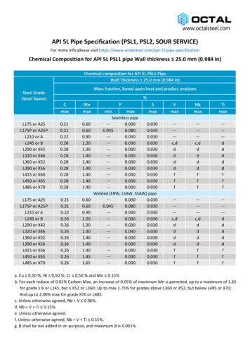
Strength of MaterialLab Manual2018-19EXPERIMENT NO-06AIM: - To Determine the Hardness of a Mild Steel.OBJECT: - To conduct hardness test on mild steel, carbon steel, brass andaluminum specimens.APPARATUS:- Hardness tester, soft and hard mild steel specimens, brass,aluminum etc.DIAGRAM:-THEORY: - The hardness of a material is resistance to penetration under a localizedpressure or resistance to abrasion. Hardness tests provide an accurate, rapid andeconomical way of determining the resistance of materials to deformation. There arethree general types of hardness measurements depending upon the manner in whichthe test is conducted:a. Scratch hardness measuremen
Strength of Material Lab Manual 2018-19 Program Educational Objectives (PEOs) Apply technical knowledge to find solution to the challenges in various areas and to develop independent thinking in the field of Civil Engineering. Have analyze, design, technica