Transcription
Source: Optical Communications EssentialsChapter1Basic Concepts ofCommunication SystemsEver since ancient times, people continuously have devised new techniques andtechnologies for communicating their ideas, needs, and desires to others. Thus,many forms of increasingly complex communication systems have appearedover the years. The basic motivations behind each new one were to improve thetransmission fidelity so that fewer errors occur in the received message, toincrease the transmission capacity of a communication link so that more information could be sent, or to increase the transmission distance between relay stations so that messages can be sent farther without the need to restore the signalfidelity periodically along its path.Prior to the nineteenth century, all communication systems operated at a verylow information rate and involved only optical or acoustical means, such as signallamps or horns. One of the earliest known optical transmission links, for example, was the use of a fire signal by the Greeks in the eighth century B.C. for sending alarms, calls for help, or announcements of certain events. Improvements ofthese systems were not pursued very actively because of technology limitations atthe time. For example, the speed of sending information over the communicationlink was limited since the transmission rate depended on how fast the senderscould move their hands, the receiver was the human eye, line-of-sight transmission paths were required, and atmospheric effects such as fog and rain made thetransmission path unreliable. Thus it turned out to be faster, more efficient, andmore dependable to send messages by a courier over the road network.The invention of the telegraph by Samuel F. B. Morse in 1838 ushered in anew epoch in communications—the era of electrical communications. In the ensuing years increasingly sophisticated and more reliable electrical communicationsystems with progressively larger information capacities were developed anddeployed. This activity led to the birth of free-space radio, television, microwave,and satellite links, and high-capacity terrestrial and undersea wire lines forsending voice and data (and advertisements!) to virtually anywhere in the world.1Downloaded from Digital Engineering Library @ McGraw-Hill (www.digitalengineeringlibrary.com)Copyright 2004 The McGraw-Hill Companies. All rights reserved.Any use is subject to the Terms of Use as given at the website.
Basic Concepts of Communication Systems2Chapter OneHowever, since the physical characteristics of both free-space and electricwire-based communication systems impose an upper bound on the transmissioncapacities, alternative transmission media were investigated. A natural extension was the use of optical links. After extensive research and development onthe needed electrooptical components and the glass equivalent of a copper wire,optical fiber communication systems started to appear in the 1970s. It is thistechnology that this book addresses.To exchange information between any two devices in a communication system,some type of electric or optical signal which carries this information has to betransmitted from one device to the other via a communication channel. Thischannel could consist of a wire, radio, microwave, satellite, infrared, or opticalfiber link. Each of the media used for such communication channels has uniqueperformance characteristics associated with it. Regardless of its type, the mediumdegrades the fidelity of the transmitted signal because of an imperfect responseto the signal and because of the presence of electrical and/or optical noise andinterference. This can lead to misinterpretations of the signal by the electronicsat the receiving end. To understand the various factors that affect the physicaltransfer of information-bearing signals, this chapter gives a basic overview offundamental data communication concepts. With that as a basis, the followingchapters will describe how information is transferred using lightwave technology.1.1. DefinitionsWe start by giving some concepts and definitions used in data communicationsand the possible formats of a signal. The signal format is an important factor inefficiently and reliably sending information across a network.A basic item that appears throughout any communications book is the prefixused in metric units for designating parameters such as length, speed, powerlevel, and information transfer rate. Although many of these are well known, afew may be new to some readers. As a handy reference, Table 1.1 lists standardprefixes, their symbols, and their magnitudes, which range in size from 1024 to10 24. As an example, a distance of 2 10 9 m (meters) 2 nm (nanometers).The three highest and lowest designations are not especially common in communication systems (yet!), but are included in Table 1.1 for completeness.Next let us define some terms and concepts that are used in communications. Information has to do with the content or interpretation of something such asspoken words, a still or moving image, the measurement of a physical characteristic, or values of bank accounts or stocks. A message may be considered as the physical manifestation of the informationproduced by the source. That is, it can range from a single number or symbolto a long string of sentences. The word data refers to facts, concepts, or instructions presented as some typeof encoded entities that are used to convey the information. These can includeDownloaded from Digital Engineering Library @ McGraw-Hill (www.digitalengineeringlibrary.com)Copyright 2004 The McGraw-Hill Companies. All rights reserved.Any use is subject to the Terms of Use as given at the website.
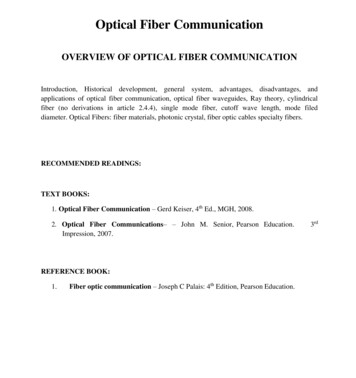
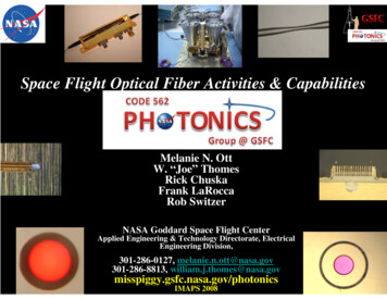
Basic Concepts of Communication SystemsBasic Concepts of Communication Systems3TABLE 1.1. Metric Prefixes, Their Symbols, and Their 000Million106kilokThousand103centic0.01Hundredth10 2millim0.001Thousandth10 3microµ0.000001Millionth10 6nanon0.000000001Billionth10 9picopTrillionth10 12femtofQuadrillionth10 15attoa10 18zeptoz10 21yoctoy10 241,000arrays of integers, lines of text, video frames, digital images, and so on. Althoughthe words data and message each have a specific definition, these terms oftenare used interchangeably in the literature since they represent physical embodiments of information. Signals are electromagnetic waves (in encoded electrical or optical formats)used to transport the data over a physical medium.A block diagram of an elementary communication link is shown in Fig. 1.1.The purpose of such a link is to transfer a message from an originating user,called a source, to another user, called the destination. In this case, let us assumethe end users are two communicating computers attached to different local areanetworks (LANs). The output of the information source serves as the messageinput to a transmitter. The function of the transmitter is to couple the messageonto a transmission channel in the form of a time-varying signal that matchesthe transfer properties of the channel. This process is known as encoding.As the signal travels through the channel, various imperfect properties of thechannel induce impairments to the signal. These include electrical or opticalnoise effects, signal distortions, and signal attenuation. The function of thereceiver is to extract the weakened and distorted signal from the channel,amplify it, and restore it as closely as possible to its original encoded form beforedecoding it and passing it on to the message destination.Downloaded from Digital Engineering Library @ McGraw-Hill (www.digitalengineeringlibrary.com)Copyright 2004 The McGraw-Hill Companies. All rights reserved.Any use is subject to the Terms of Use as given at the website.
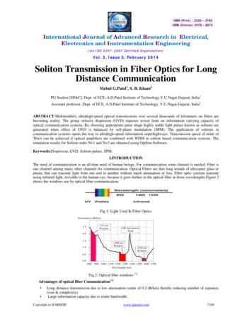
Basic Concepts of Communication Systems4Chapter OneFigure 1.1. Block diagram of a typical communication link connectingseparate LANs.1.2. Analog Signal FormatsThe signals emitted by information sources and the signals sent over a transmission channel can be classified into two distinct categories according to their physical characteristics. These two categories encompass analog and digital signals.An analog signal conveys information through a continuous and smooth variation in time of a physical quantity such as optical, electrical, or acoustical intensities and frequencies. Well-known analog signals include audio (sound) and videomessages. As examples, An optical signal can vary in color (which is given in terms of its wavelengthor its frequency, as described in Chap. 3), and its intensity may change fromdim to bright. An electric signal can vary in frequency (such as the kHz, MHz, GHz designations in radio communications), and its intensity can range from low tohigh voltages. The intensity of an acoustical signal can range from soft to loud, and its tonecan vary from a low rumble to a very high pitch.The most fundamental analog signal is the periodic sine wave, shown inFig. 1.2. Its three main characteristics are its amplitude, period or frequency,and phase. The amplitude is the size or magnitude of the waveform. This isgenerally designated by the symbol A and is measured in volts, amperes, orwatts, depending on the signal type. The frequency (designated by f ) is theDownloaded from Digital Engineering Library @ McGraw-Hill (www.digitalengineeringlibrary.com)Copyright 2004 The McGraw-Hill Companies. All rights reserved.Any use is subject to the Terms of Use as given at the website.
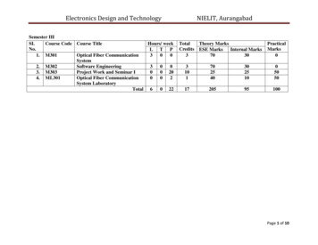
Basic Concepts of Communication SystemsBasic Concepts of Communication Systems5Amplitude0TimePeriod 1/f1/f1/fFigure 1.2. Characteristics of a basic sine wave.AmplitudeWave 1A10TimeAmplitudeWave 2A20TimeA1 A 21.3. Two in-phasewaves will add constructively.Figurenumber of cycles per second that the wave undergoes (i.e., the number of timesit oscillates per second), which is expressed in units of hertz (Hz). A hertz refersto a complete cycle of the wave. The period (generally represented by the symbol T ) is the inverse of the frequency, that is, period T 1/f. The term phase(designated by the symbol φ) describes the position of the waveform relative totime 0, as illustrated in Fig. 1.3. This is measured in degrees or radians (rad):180 π rad.If the crests and troughs of two identical waves occur at the same time, theyare said to be in phase. Similarly, if two points on a wave are separated by wholemeasurements of time or of wavelength, they also are said to be in phase. Forexample, wave 1 and wave 2 in Fig. 1.3 are in phase. Let wave 1 have an amplitude A1 and let wave 2 have an amplitude A2. If these two waves are added, theamplitude A of the resulting wave will be the sum: A A1 A2. This effect isknown as constructive interference.Figure 1.4 illustrates some phase shifts of a wave relative to time 0. When twowaves differ slightly in their relative positions, they are said to be out of phase.As an illustration, the wave shown in Fig. 1.4c is 180 (π rad) out of phasewith the wave shown in Fig. 1.4a. If these two waves are identical and havethe same amplitudes, then when they are superimposed, they cancel eachother out, which is known as destructive interference. These concepts are ofDownloaded from Digital Engineering Library @ McGraw-Hill (www.digitalengineeringlibrary.com)Copyright 2004 The McGraw-Hill Companies. All rights reserved.Any use is subject to the Terms of Use as given at the website.
Basic Concepts of Communication Systems6Chapter OneAmplitudeAmplitude0Time(a) 0 01/4 cycleAmplitude01/2 cycleTime(b) 90 AmplitudeTime(c) 180 0Time(d) 270 Addition of two waves that areπ radians out of phase yieldszero final amplitudeFigure 1.4. Examples of phase differences between two sine waves. Two waves thatare 180 out of phase will add destructively.importance when one is considering the operation of optical couplers, asdescribed in Chap. 8.Example A sine wave has a frequency f 5 kHz. Its period is T 1/5000 s 0.20 ms.A sine wave has a period T 1 ns. Its frequency is f 1/(10 9 s) 1 GHz.A sine wave is offset by 1/4 cycle with respect to time 0. Since 1 cycle is 360 , the phaseshift is φ 0.25 360 90 π/2 rad.Two further common characteristics in communications are the frequencyspectrum (or simply spectrum) and the bandwidth of a signal. The spectrum ofa signal is the range of frequencies that it contains. That is, the spectrum of asignal is the combination of all the individual sine waves of different frequencieswhich make up that signal. The bandwidth (designated by B) refers to the widthof this spectrum.Example If the spectrum of a signal ranges from its lowest frequency flow 2 kHz toits highest frequency fhigh 22 kHz, then the bandwidth B fhigh flow 20 kHz.1.3. Digital Signal FormatsA digital signal is an ordered sequence of discrete symbols selected from a finiteset of elements. Examples of digital signals include the letters of an alphabet,Downloaded from Digital Engineering Library @ McGraw-Hill (www.digitalengineeringlibrary.com)Copyright 2004 The McGraw-Hill Companies. All rights reserved.Any use is subject to the Terms of Use as given at the website.
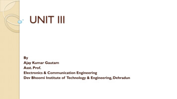
Basic Concepts of Communication SystemsBasic Concepts of Communication Systems100110170tBit duration1T 1/R bit interval(a)0011010T bit intervalBit duration(b)Figure 1.5. Examples of two binary waveforms showing theiramplitude, period, and bit duration. (a) The bit fills the entireperiod for 1 bit only; (b) a 1 bit fills the first half and a 0 bit fillsthe second half of a period.numbers, and other symbols such as @, #, or %. These discrete symbols arenormally represented by unique patterns of pulses of electric voltages or opticalintensity that can take on two or more levels.A common digital signal configuration is the binary waveform shown in Fig. 1.5.A binary waveform is represented by a sequence of two types of pulses of knownshape. The information contained in a digital signal is given by the particularsequence of the presence (a binary one, or simply either one or 1) and absence(a binary zero, or simply either zero or 0) of these pulses. These are known commonly as bits (this word was derived from binary digits). Since digital logic is usedin the generation and processing of 1 and 0 bits, these bits often are referred toas a logic one (or logic 1) and a logic zero (or logic 0), respectively.The time slot T in which a bit occurs is called the bit interval, bit period, orbit time. (Note that this T is different from the T used for designating the periodof a waveform.) The bit intervals are regularly spaced and occur every 1/R seconds (s), or at a rate of R bits per second (abbreviated as bps in this book), whereR is called the bit rate or the data rate. As an example, a data rate of 2 109 bitsper second (bps) 2 Gbps (gigabits per second). A bit can fill the entire bit interval or part of it, as shown in Fig. 1.5a and b, respectively.A block of 8 bits often is used to represent an encoded symbol or word and isreferred to as an octet or a byte.1.4. Digitization of Analog SignalsAn analog signal can be transformed to a digital signal through a process ofperiodic sampling and the assignment of quantized values to represent theintensity of the signal at regular intervals of time.To convert an analog signal to a digital form, one starts by taking instantaneous measures of the height of the signal wave at regular intervals, which iscalled sampling the signal. One way to convert these analog samples to aDownloaded from Digital Engineering Library @ McGraw-Hill (www.digitalengineeringlibrary.com)Copyright 2004 The McGraw-Hill Companies. All rights reserved.Any use is subject to the Terms of Use as given at the website.
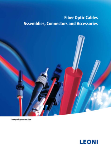
Basic Concepts of Communication SystemsChapter Onedigital format is to simply divide the amplitude excursion of the analog signalinto N equally spaced levels, designated by integers, and to assign a discretebinary word to each of these N integer values. Each analog sample is thenassigned one of these integer values. This process is known as quantization.Since the signal varies continuously in time, this process generates a sequenceof real numbers.Example Figure 1.6 shows an example of digitization. Here the allowed voltageamplitude excursion is divided into eight equally spaced levels ranging from 0 to V volts(V). In this figure, samples are taken every second, and the nearest discrete quantizationlevel is chosen as the one to be transmitted, according to the 3-bit binary code listednext to the quantized levels shown in Fig. 1.6. At the receiver this digital signal is thendemodulated. That is, the quantized levels are reassembled into a continuously varyinganalog waveform.Nyquist Theorem Note that the equally spaced levels in Fig. 1.6 are the simplestquantization implementation, which is produced by a uniform quantizer. Frequentlyit is more advantageous to use a nonuniform quantizer where the quantization levelsare roughly proportional to the signal level. The companders used in telephone systems are an example of e 1.6. Digitization of analog waveforms. (a) Original sig-nal varying between 0 and V volts; (b) quantized and sampleddigital version.Downloaded from Digital Engineering Library @ McGraw-Hill (www.digitalengineeringlibrary.com)Copyright 2004 The McGraw-Hill Companies. All rights reserved.Any use is subject to the Terms of Use as given at the website.
Basic Concepts of Communication SystemsBasic Concepts of Communication Systems9Intuitively, one can see that if the digitization samples are taken frequently enoughrelative to the rate at which the signal varies, then to a good approximation the signal can be recovered from the samples by drawing a straight line between the sample points. The resemblance of the reproduced signal to the original signal dependson the fineness of the quantizing process and on the effect of noise and distortionadded into the transmission system. According to the Nyquist theorem, if the sampling rate is at least 2 times the highest frequency, then the receiving device canfaithfully reconstruct the analog signal. Thus, if a signal is limited to a bandwidth ofB Hz, then the signal can be reproduced without distortion if it is sampled at a rateof 2B times per second. These data samples are represented by a binary code. Asnoted in Fig. 1.6, eight quantized levels having upper bounds V1, V2, . . . , V can bedescribed by 3 binary digits (23 8). More digits can be used to give finer samplinglevels. That is, if n binary digits represent each sample, then one can have 2n quantization levels.1.5. Electromagnetic SpectrumTo understand the distinction between electrical and optical communicationsystems and what the advantages are of lightwave technology, let us examinethe spectrum of electromagnetic (EM) radiation shown in Fig. 1.7.1.5.1. Telecommunication spectral bandAll telecommunication systems use some form of electromagnetic energy to transmit signals from one device to another. Electromagnetic energy is a combinationof electrical and magnetic fields and includes power, radio waves, microwaves,infrared light, visible light, ultraviolet light, x rays, and gamma rays. Each ofthese makes up a portion (or band) of the electromagnetic spectrum. The fundamental nature of all radiation within this spectrum is the same in that it canbe viewed as electromagnetic waves that travel at the speed of light, which isFigure 1.7. The spectrum of electromagnetic radiation.Downloaded from Digital Engineering Library @ McGraw-Hill (www.digitalengineeringlibrary.com)Copyright 2004 The McGraw-Hill Companies. All rights reserved.Any use is subject to the Terms of Use as given at the website.
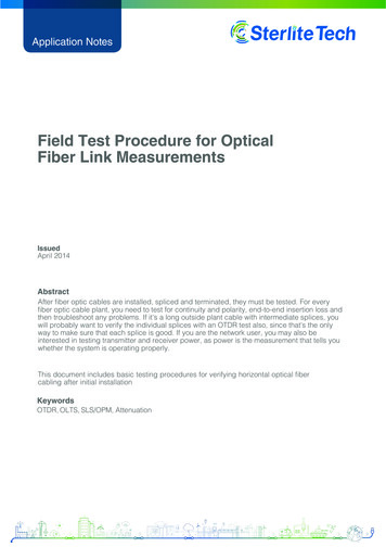
Basic Concepts of Communication Systems10Chapter Oneabout c 300,000 kilometers per second (3 10 8 m/s) or 180,000 miles persecond (1.8 10 5 mi/s) in a vacuum. Note that the speed of light in a materialis less than c, as described in Chap. 3.The physical property of the radiation in different parts of the spectrum canbe measured in several interrelated ways. These are the length of one period ofthe wave, the energy contained in the wave, or the oscillating frequency of thewave. Whereas electric signal transmission tends to use frequency to designatethe signal operating bands, optical communications generally use wavelength todesignate the spectral operating region and photon energy or optical powerwhen discussing topics such as signal strength or electrooptical component performance. We will look at the measurement units in greater detail in Chap. 3.1.5.2. Optical communications bandThe optical spectrum ranges from about 5 nm (ultraviolet) to 1 mm (far infrared),the visible region being the 400- to 700-nm band. Optical fiber communicationsuse the spectral band ranging from 800 to 1675 nm.The International Telecommunications Union (ITU) has designated sixspectral bands for use in intermediate-range and long-distance optical fibercommunications within the 1260- to 1675-nm region. As Chap. 4 describes,these band designations arose from the physical characteristics of optical fibersand the performance behavior of optical amplifiers. As shown in Fig. 1.8, theregions are known by the letters O, E, S, C, L, and U, which are defined asfollows: Original band (O-band): 1260 to 1360 nm Extended band (E-band): 1360 to 1460 nm Short band (S-band): 1460 to 1530 nm Conventional band (C-band): 1530 to 1565 nm Long band (L-band): 1565 to 1625 nm Ultralong band (U-band): 1625 to 1675 nmThe operational performance characteristics and applications of optical fibers,electrooptic components, and other passive optical devices for use in thesebands are described in later chapters.Figure 1.8. Definitions of spectral bands for use in optical fiber communications.Downloaded from Digital Engineering Library @ McGraw-Hill (www.digitalengineeringlibrary.com)Copyright 2004 The McGraw-Hill Companies. All rights reserved.Any use is subject to the Terms of Use as given at the website.
Basic Concepts of Communication SystemsBasic Concepts of Communication Systems111.6. Transmission ChannelsDepending on what portion of the electromagnetic spectrum is used, electromagnetic signals can travel through a vacuum, air, or other transmission media.For example, electricity travels well through copper wires but not through glass.Light, on the other hand, travels well through air, glass, and certain plasticmaterials but not through copper.1.6.1. Carrier wavesAs electrical communication systems became more sophisticated, an increasinglygreater portion of the electromagnetic spectrum was utilized for conveying largeramounts of information faster from one place to another. The reason for thisdevelopment trend is that in electrical systems the physical properties of varioustransmission media are such that each medium type has a different frequencyband in which signals can be transported efficiently. To utilize this property, information usually is transferred over the communication channel by superimposingthe data onto a sinusoidally varying electromagnetic wave, which has a frequencyresponse that matches the transfer properties of the medium. This wave is knownas the carrier. At the destination the information is removed from the carrierwave and processed as desired. Since the amount of information that can betransmitted is directly related to the frequency range over which the carrier operates, increasing the carrier frequency theoretically increases the available transmission bandwidth and, consequently, provides a larger information capacity.To send digital information on a carrier wave, one or more of the characteristicsof the wave such as its amplitude, frequency, or phase are varied. This kind of modification is called modulation or shift keying, and the digital information signalis called the modulating signal. Figure 1.9 shows an example of amplitude shiftkeying (ASK) or on/off keying (OOK) in which the strength (amplitude) of thecarrier wave is varied to represent 1 or 0 pulses. Here a high amplitude represents a 1 and a low amplitude is a 0.Thus the trend in electrical communication system developments was toemploy progressively higher frequencies, which offer correspondingincreases in bandwidth or information capacity. However, beyond a certaincarrier frequency, electrical transmission systems become extremely difficultto design, build, and operate. These limitations, plus the inherent advantages of smaller sizes and lower weight of dielectric transmission materialsFigure 1.9. Concept of carrier waves.Downloaded from Digital Engineering Library @ McGraw-Hill (www.digitalengineeringlibrary.com)Copyright 2004 The McGraw-Hill Companies. All rights reserved.Any use is subject to the Terms of Use as given at the website.
Basic Concepts of Communication Systems12Chapter Onesuch as glass, prompted researchers to consider optical fiber transmissiontechnology.1.6.2. Baseband signalsBaseband refers to the technology in which a signal is transmitted directly ontoa channel without modulating a carrier. For example, this method is used onstandard twisted-pair wire links running from an analog telephone to the nearest switching interface equipment.The same baseband method is used in optical communications; that is, the optical output from a light source is turned on and off in response to the variationsin voltage levels of an information-bearing electric signal. As is described inChap. 6, for data rates less than about 2.5 Gbps, the light source itself can beturned on and off directly by the electric signal. For data rates higher than2.5 Gbps, the optical output from a source such as a laser cannot respond fastenough. In this case an external device is used to modulate a steady optical output from a laser source.1.7. Signal MultiplexingStarting in the 1990s, a burgeoning demand on communication network assetsemerged for services such as database queries and updates, home shopping,video-on-demand, remote education, audio and video streaming, and video conferencing. This demand was fueled by the rapid proliferation of personal computers coupled with a phenomenal increase in their storage capacity andprocessing capabilities, the widespread availability of the Internet, and anextensive choice of remotely accessible programs and information databases. Tohandle the ever-increasing demand for high-bandwidth services from usersranging from home-based computers to large businesses and research organizations, telecommunication companies worldwide are implementing increasinglysophisticated digital multiplexing techniques that allow a larger number ofindependent information streams to share the same physical transmissionchannel. This section describes some common techniques. Chapter 2 describesmore advanced methodologies used and proposed for optical fiber transport systems.Table 1.2 gives examples of information rates for some typical voice, video, anddata services. To send these services from one user to another, network providerscombine the signals from many different users and send the aggregate signal overa single transmission line. This scheme is known as time-division multiplexing(TDM). Here N independent information streams, each running at a data rate ofR bps (bits per second), are interleaved electrically into a single informationstream operating at a higher rate of N R bps. To get a detailed perspective ofthis, let us look at the multiplexing schemes used in telecommunications.Early applications of fiber optic transmission links were mainly for largecapacity telephone lines. These digital links consisted of time-division multiplexedDownloaded from Digital Engineering Library @ McGraw-Hill (www.digitalengineeringlibrary.com)Copyright 2004 The McGraw-Hill Companies. All rights reserved.Any use is subject to the Terms of Use as given at the website.
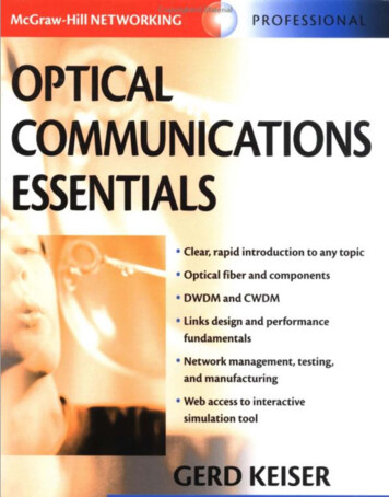
Basic Concepts of Communication SystemsBasic Concepts of Communication Systems13TABLE 1.2. Examples of Information Rates for Some TypicalVoice, Video, and Data ServicesType of serviceData rateVideo on demand/interactive TV1.5 to 6 MbpsVideo games1 to 2 MbpsRemote education1.5 to 3 MbpsElectronic shopping1.5 to 6 MbpsData transfer or telecommuting1 to 3 MbpsVideo conferencing0.384 to 2 MbpsVoice (single channel)64 kbpsFigure 1.10. Digital transmission hierarchy used in the NorthAmerican telephone network.64-kbps voice channels. The multiplexing was developed in the 1960s and is basedon what is known as the plesiochronous digital hierarchy (PDH). Figure 1.10shows the digital transmission hierarchy used in the North American telephonenetwork. The fundamental building block is a 1.544-Mbps transmission rateknown as a DS1 rate, where DS stands for digital system. It is formed by timedivision multiplexing 24 voice channels, each digitized at a 64-kbps rate (whichis referred to as DS0). Framing bits, which indicate where an information unitstarts and ends, are added along with these voice channels to yield the 1.544-Mbpsbit stream. At any level a signal at the designated input rate is multiplexed withother input signals at the same rate.DSn versus Tn In describing telephone network data rates, one also sees the termsT1, T3, and so on. Often people use the terms Tn and DSn (for example, T1 and DS1or T3 and DS3) interchangeably. However there is a subtle difference in their meaning.DS1, DS2, DS3, and so on refer to a service type; for example, a user who wants to sendinformation at a 1.544-Mbps rate would subscribe to a DS1 service. T1, T2, T3, and soon refer to the technology used to deliver that service over a physical link. For example,Downloaded from Digital Engineering Library @ McGraw-Hill (www.digitalengineeringlibrary.com)Co
optical fiber communication systems started to appear in the 1970s. It is this technology that this book addresses. To exchange information between any two devices in a communication system, some type of electric or optical signal which carries this information has to be transmitted from one device to the other via a communication channel. This