Transcription
User GuideMHM-97927-PBF, Rev DRAFTJuly 2020AMS Wireless Vibration MonitorUser Guide
Copyright 2020 by Emerson. All rights reserved.No part of this publication may be reproduced, transmitted, transcribed, stored in a retrieval system, or translated into anylanguage in any form by any means without the written permission of Emerson.DisclaimerThis manual is provided for informational purposes. EMERSON MAKES NO WARRANTY OF ANY KIND WITH REGARD TO THISMATERIAL, INCLUDING, BUT NOT LIMITED TO, THE IMPLIED WARRANTIES OF MERCHANTABILITY AND FITNESS FOR A PARTICULARPURPOSE. Emerson shall not be liable for errors, omissions, or inconsistencies that may be contained herein or for incidental orconsequential damages in connection with the furnishing, performance, or use of this material. Information in this document issubject to change without notice and does not represent a commitment on the part of Emerson. The information in this manual isnot all-inclusive and cannot cover all unique situations.PatentsThe product(s) described in this manual are covered under existing and pending patents.Where to get helpSoftware RegistrationPhone:Toll free 888.367.3774, option 2 (U.S. and Canada) 63.2.702.1111 (Rest of w.emerson.com/machineryhealthregProduct SupportEmerson provides a variety of ways to reach your Product Support team to get the answers you need when you need them:PhoneToll free 800.833.8314 (U.S. and Canada) 1.512.832.3774 (Latin America) 63.2 702.1111 (Asia Pacific, Europe, and Middle com/en-us/contact-usTo search for documentation, visit http://www.emerson.com.To view toll free numbers for specific countries, visit http://www.emerson.com/technicalsupport.2
User GuideContentsMHM-97927-PBFJuly 2020ContentsChapter 1Introduction. 5Chapter 2Configuration.13Chapter 3Installation.39Chapter 4Operation. 45Chapter 5Overall Velocity, PeakVue, and temperature. 53Appendix ASpecifications and reference data. 63Appendix BProduct certifications.67Index. 75MHM-97927-PBF, DRAFTiii
ContentsJuly 2020ivUser GuideMHM-97927-PBFMHM-97927-PBF, DRAFT
User GuideIntroductionMHM-97927-PBFJuly 20201Introduction1.1Safety messagesInstructions in this manual may require special precautions to ensure the safety of thepersonnel performing the operations.This AMS Wireless Vibration Monitor device complies with Part 15 of the FCC Rules.Operation is subject to the following conditions: This device may not cause harmfulinterference, this device must accept any interference received, including interferencethat may cause undesired operation.This device must be installed to ensure a minimum antenna separation of 20 cm from allpersons.Refer to the following safety messages before performing an operation preceded by thewarning symbol:WARNINGFailure to follow these installation guidelines can result in death or serious injury. Onlyqualified personnel should install the AMS Wireless Vibration Monitor.Explosions could result in death or serious injury: Before connecting a Field Communicator in an explosive environment, make sure theinstruments are installed in accordance with applicable field wiring practices. Verify that the operating environment of the AMS Wireless Vibration Monitor isconsistent with the appropriate hazardous locations certifications.MHM-97927-PBF, DRAFT5
IntroductionUser GuideJuly 20201.2MHM-97927-PBFOverviewThe manualThis User Guide applies to the AMS Wireless Vibration Monitor, a triaxial vibrationmeasurement device designed for use on a WirelessHART network.Use this manual to install, operate, and maintain the device.The monitorThe AMS Wireless Vibration Monitor is an installation-ready solution that monitorsvibration and temperature in rotating equipment in hard-to-reach locations.The AMS Wireless Vibration Monitor also provides a variety of monitor and sensorconfigurations. It has built-in radio and four integral sensors: X and Y MEMS Z MEMS High Sensitivity, High Bandwidth (Vibration & PeakVue) Temperature sensorThe Z accelerometer has the highest bandwidth and is considered the primary sensor. Thetemperature sensor is designed to measure the temperature near the mounting point(i.e., the machine’s skin temperature).Other features include: Support for up to 13 device variables with up to three user-configurable alerts for eachprocess variable. Any device variable can be configured as any process variable (PV, SV,TV, QV). Support for storage of Waveform/Spectrum directly in AMS Machine Works Wireless output with 99% data reliability, delivering rich HART data, protected byindustry leading security (when operated as part of a well-formed network)The device uses an off-the-shelf battery contained in the device which is easily removablefor device installation and replacement.6MHM-97927-PBF, DRAFT
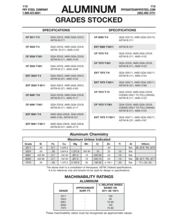
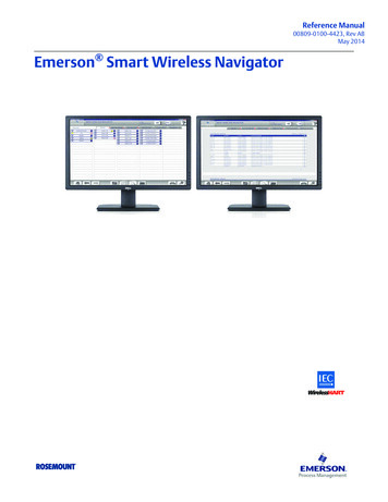
User GuideIntroductionMHM-97927-PBFJuly 2020Parts of the monitorA.B.C.D.MHM-97927-PBF, DRAFTChassisHART TerminalsTool holeMounting screw7
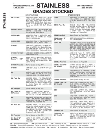
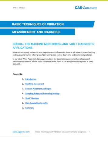
IntroductionUser GuideJuly 2020MHM-97927-PBFA.B.C.D.E.CoverBattery clampBatteryBattery pull tabBase O-ringMeasurementsThe device supports the following measurements. Any of these can be configured as aprocess variable.8Device variable indexDevice variables1Z-Velocity2Z-Peakvue3Machine Temperature4Supply Voltage5X-Velocity6Y-Velocity7AP1 (Velocity)8AP2 (Velocity)9AP3 (Acceleration)10AP4 (Accleration)11Speed Estimate12Mechanical Condition13Lubrication ConditionMHM-97927-PBF, DRAFT
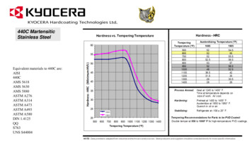
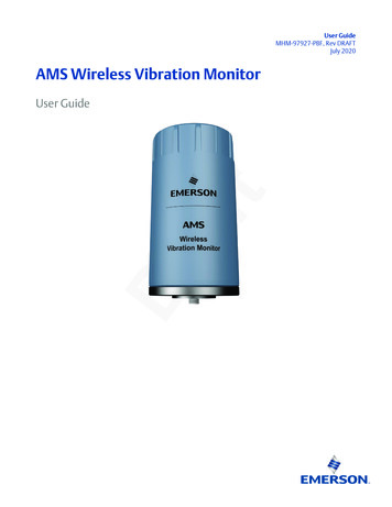
User GuideIntroductionMHM-97927-PBFJuly 2020Device revision information1RevisionCurrent levelDescriptionUniversal7This is the HART version the monitor supports.Field device11This is the major revision of the monitor and corresponds with amajor interface release.When using AMS Device Manager, this revision can be found onthe screen title.Software43This is the current software version.The software may be occasionally modified to refinefunctionality. When major functionality is added, the devicerevision increases.Hardware1This is the hardware revision.DD1This is the Device Descriptor (DD) revision.The device descriptor is primarily used for configuring devices inthe field.If you have an older device revision, a factory upgrade may be possible in some cases. ContactProduct Support for more information.You can also view the revision information in AMS Device Manager and TrexCommunicator.Figure 1-1: Revision numbers in AMS Device ManagerMHM-97927-PBF, DRAFT9
IntroductionUser GuideJuly l vibration sensors, such as accelerometers, produce low-level signals proportionalto their sensed vibration. With simple HART configuration, the monitor converts the lowlevel sensor signal to a wireless-enabled signal.CommissioningThe monitor can be commissioned before or after installation. You can commission it onthe bench before installation to ensure proper operation and to be familiar with itsfunctions.Make sure the instruments are installed in accordance with applicable field wiringpractices.The AMS Wireless Vibration Monitor is powered whenever the battery is installed.InstallationWhen choosing an installation location and position, provide ample access to the monitor.The device should be mounted vertically, perpendicular to the shaft and on the bearingcase. Horizontal mounting is also an option. For more information, see Install the AMSWireless Vibration Monitor.BatteryThe AMS Wireless Vibration Monitor uses an off-the-shelf Tadiran TL-4920/VE battery.The battery comes with the device but it is not connected when the device is shipped. Youneed to connect the battery before configuring and installing the device.EnvironmentalThe monitor operates within specifications for ambient temperatures between –40 F and185 F (–40 C and 85 C).Verify that the operating environment of the monitor is consistent with the appropriatehazardous location certifications.1.4Return of materialsYou may need to ship the device to an Emerson Product Service Center for return orreplacement in case of warranty issues. Before shipping, contact Emerson Product Supportto obtain a Return Materials Authorization (RMA) number and receive additionalinstructions.Emerson Product Support contact information:10PhoneToll free 800.833.8314 (U.S. and Canada) 1.512.832.3774 (Latin America) 63.2 702.1111 (Asia Pacific, Europe, and Middle com/en-us/contact-usMHM-97927-PBF, DRAFT
User GuideIntroductionMHM-97927-PBFJuly 2020NoteIf the monitor has been exposed to hazardous substances, a Material Safety Data Sheet(MSDS) must be included with the returned materials. An MSDS is required by law to beavailable to people exposed to specific hazardous substances.Shipping considerations for wireless products (Lithium Batteries) The unit was shipped to you with the battery inside but disconnected. Connect thebattery for proper operation. Primary lithium batteries are regulated in transportation by the U.S. Department ofTransportation, and are also covered by IATA (International Air Transport Association),ICAO (International Civil Aviation Organization), and ADR (European GroundTransportation of Dangerous Goods). It is the responsibility of the shipper to ensure compliance with these or any other localrequirements. Please consult current regulations and requirements before shipping.MHM-97927-PBF, DRAFT11
IntroductionJuly 202012User GuideMHM-97927-PBFMHM-97927-PBF, DRAFT
User GuideConfigurationMHM-97927-PBFJuly 20202Configuration2.1Configuration setupUnless the AMS Wireless Vibration Monitor is purchased pre-configured from the factory,it needs to be configured prior to installation at the facility or measurement location.There are three possible setups to configure the device:1. Connect the device to a field communicator, and then configure the device usingthe field communicator.NoteThis setup is recommended if you are in a hazardous area.2. Connect the device to a computer through a HART modem, and then configure thedevice using AMS Device Manager.NoteThe HART modem is purchased separately.3. Connect the device to a computer through a wireless gateway and then configurethe device using AMS Device Manager.NoteThis setup is recommended for standard device configuration.MHM-97927-PBF, DRAFT13
ConfigurationUser GuideJuly 20202.1.1MHM-97927-PBFPre-configurationThe AMS Wireless Vibration Monitor is shipped with the battery disconnected to complywith safety requirements. You need to connect the battery to the device before you canconfigure the device.Procedure1. Remove the cover of the device.This exposes the HART ports.Use an Allen wrench or a small screwdriver and put it through the Tool hole to useas leverage while loosening the cover.Safety note: Exercise caution when using your bare hands to remove the cover.2. Attach the battery connector, insert the battery, and then lock it into place.3. Connect the device to a computer or field communicator through the HARTconnectors on the side of the device.4. Configure the device. To configure the device using AMS Device Manager, see Configuration with AMSDevice Manager.14MHM-97927-PBF, DRAFT
User GuideConfigurationMHM-97927-PBFJuly 2020 To configure the device using AMS Trex Communicator, see Configure with TrexCommunicator.5. Mount the cover and then tighten it.To avoid depleting the battery, disconnect it when the device is not in use. If youhave configured the device and network but are not ready to commission it,remove the battery to extend its operating life.2.1.2Configuration overviewNoteThe specific user interface for performing the configuration varies depending on the hostused. To view the default values, see Configuration defaults.Procedure1. Connect to a wired HART interface.You need to connect to a wired connection to set the wireless credentials.2. Set the wireless network credentials (Network ID and Join Key) using wiredconnection.The monitor has a default Network ID and Join Key. You can change the networkcredentials in the gateway that you used for configuration. All devices should jointhe network once the battery is connected.After the device has joined the network, you can complete the rest of theconfiguration steps over a wireless connection.3. (Optional) Name the device (Tag and Device Description).By default, the tag is VXAABBCC, where AABBCC: is the unique device ID. Thedevice joins the network and operates correctly even if no changes are made, but itis recommended to name the device something meaningful for the specificapplication.4. Specify the units (English, metric, or SI) that will be used for each parameter.By default, units are set to English, unless the device is shipped to Japan.MHM-97927-PBF, DRAFT15
ConfigurationUser GuideJuly 2020MHM-97927-PBF5. Specify which measurements (velocity, temperature, etc.) correspond to theprocess variables PV, SV, TV, and QV. Specify the units (English, metric, or SI)for each parameter.By default, PV corresponds to Z-axis overall, SV is X-axis overall, TV is Y-axis overall,and QV is Z-axis PeakVue.6. Specify alert levels.Determine the thresholds at which measurement alerts will display and determinethe behavior of device alerts. See the alert limits in Device variable alert limits7. Specify the update rate.The default update rate is once every 60 minutes. A faster update rate is notrecommended as it significantly reduces battery life.8. Configure trending of parameters.You can trend parameters in multiple locations such as in a plant historian, in AMSMachine Works, and in a DCS control system.16MHM-97927-PBF, DRAFT
User GuideConfigurationMHM-97927-PBF2.1.3July 2020Connect to a wired HART interfaceYou need to initially connect the device to a wired HART interface to define the credentialsthat allow it to communicate on a wireless network. You can also define other deviceconfigurations such as sensor type and alert thresholds at this time.NotesUse the wired HART interface only for configuration. Dynamic variables (such as measuredvibration parameters) are not updated when communicating on the wired interface.Procedure1. Connect the device to a computer or field communicator such as AMS Trex throughthe HART connectors on the side of the device.2. Configure the device using a field Communicator, AMS Device Manager, or anyHART-enabled host.Press Send to send configuration changes to the monitor.2.1.4Set the wireless network configurationThis enables the monitor to communicate with the Emerson Wireless Gateway and withother systems. This is the wireless equivalent of connecting wires from a transmitter to acontrol system input.Procedure1. From the Emerson Wireless Gateway, click System Settings Network Network Settings to obtain the Network ID and Join Key.2. Using a field communicator or AMS Device Manager with a wired modem, enter theNetwork ID and Join Key so that they match the Network ID and Join Key from theEmerson Wireless Gateway.NoteIf the Network ID and Join Key are not identical to the gateway settings, the AMSWireless Vibration Monitor will not communicate with the network.MHM-97927-PBF, DRAFT17
ConfigurationUser GuideJuly 20202.1.5MHM-97927-PBFConfiguration optionsConfigure the device to control the following operations: How measurement results are reported and how often are they reported How and when alerts are generated Set the upper and lower limits of the alerts Set the units of measurement for the parameters Set the primary variable, secondary variable, tertiary variable, and quarternary variableYou can change these configurations from AMS Device Manager or from a fieldcommunicator such as Trex Communicator.To view the configuration defaults, see Configuration defaults.18MHM-97927-PBF, DRAFT
User GuideConfigurationMHM-97927-PBFJuly 2020Variable MappingsThe AMS Wireless Vibration Monitor has 13 device varibles. Any of the device variables canbe configured as a process variable.The process variables and their default values are as follows.Table 2-1: Process VariablesProcess VariableDefaultPVZ-axis OverallSVX-axis OverallTVY-axis OverallQVZ-axis PeakVueTable 2-2: Device VariablesDevice VariablesX-axis OverallY-axis OverallProcess VariablesAny of the 13 Device Variablescan be configured as a ProcessVariablePVSVZ-axis OverallTVZ-axis PeakVueQVVelocity Parameter 1Velocity Parameter 2Acceleration Parameter 1Acceleration Parameter 2Bearing/Mechanical SeverityLubrication SeverityCalculated SpeedSkin TemperatureSupply VoltageMHM-97927-PBF, DRAFT19
ConfigurationUser GuideJuly 2020MHM-97927-PBFMeasurement parameter unitsThe table below shows the measurement parameters and units that can be configured foreach parameter.Table 2-3: Measurement parameter n/sTemperature C FSpeedrpmSupply VoltageVConfiguration defaultsTable 2-4: Configuration Values20Configuration optionDefault valueNetwork ID1234Join Key12340000 00000000 00000000 00000000MessageWIRELESS VIBRATION TRANSMITTERDescriptionASSET NAMEDefault Long Tag FormatVX WWYYTTTTTTTDefault Short Tag FormatVXAABBCCUpdate Rate60 minutesMounting MethodNot SetMotor TypeNot SetLine FrequencyNot SetVFDNot SetMachine Noise Threshold0.05 in/secNameplate Speed RPM0 rpmDriver/Driven Ratio1X YLOR1600 linesX YFMIN2 HzX YFMAX1000 HzZ LOR1600 linesZ FMIN1000 HzMHM-97927-PBF, DRAFT
User GuideConfigurationMHM-97927-PBFJuly 2020Table 2-4: Configuration Values (continued)Configuration optionDefault valueZ FMAX1000 HzZ Peakvue LORZ velocity spectrumZ Peakvue HP Filter2Z Peakvue FMAX65Velocity Band 1 SourceZ velocity spectrumVelocity Band 1 Start2Velocity Band 1 Stop65Velocity Band 2 SourceZ velocity spectrumVelocity Band 2 Start65Velocity Band 2 Stop300Acceleration Band 1 SourceZ acceleration spectrumAcceleration Band 1 Start10Acceleration Band 1 Stop500Acceleration Band 2 SourceZ acceleration spectrumAcceleration Band 2 Start500Acceleration Band 2 Stop1000Publish modeThe device publishes all device variables and status in three bursts. In cases where a thirdparty host or other control system configures the burst configuration in a custom mode,the DD allows the user to reset the burst configuration to the default burst mode.However, it is strongly recommended that the device bursting not be manipulated as ithas been optimized to provide all device variables and status bytes, hence allowing anypotential data from the device to be cached in the gateway, minimizing opportunity forerrant communication from a 3rd party host or other control system to wake the devicedue to burst misconfiguration.Update rateThe default update rate is 60 minutes. This is the maximum (fastest) recommendedupdate rate. You can change this at commissioning or at any time through AMS DeviceManager, the Trex Communicator, or the Smart Wireless gateway web server.The update rate can be set from 1 minute to 60 minutes (with 1 second resolution) andfrom 1 hour to 24 hours (with 1 hour resolution, always rounding to the next hour).When the update rate is greater than 1 hour, the device will publish the last measurementevery hour (meeting the HART requirement to at least publish data once / hour) and willpublish the new data set on the update rate.Reducing the update rate minimizes power consumption and extends the life of thebattery.MHM-97927-PBF, DRAFT21
ConfigurationUser GuideJuly 2020MHM-97927-PBFNoteIf the device is configured to publish at the fastest allowable update rate (once perminute), the battery is expected to last only about 2-3 months.Alert levelsThe AMS Wireless Vibration Monitor sets HART status bits to indicate when measuredvalues exceed the configured thresholds. Measured values have six levels: Saturated,Sensor, Range, Advisory, Maintenance, and Failed.The level at which these thresholds should be set depends on the type of equipment beingmonitored and on your specific process.Check the alert thresholds in Device variable alert limits.One rule of thumb for vibration is to examine the current level at which the equipment isoperating. Assuming the equipment is in good working condition, set the Advisory level at2x the current value (or at a minimum of 0.05 in/s RMS, whichever is greater), set theMaintenance level at 4x the current value, and set the Failed level at 8x the current value.For example, if the current value for Overall Velocity is 0.1 in/s, set the Advisory thresholdat 0.2 in/s, the Maintenance threshold at 0.4 in/s and the Failed threshold at 0.8 in/s. Whilethis type of vibration program is not recommended, it can provide a starting point whenno other information is available.A good rule of thumb for establishing the PeakVue alert levels is to use the rule of 10's. Thisapplies for most rolling element bearing equipment with a turning speed between 900and 4000 CPM. Using this approach, the Advisory alert would be set at 10 g's, theMaintenance alert at 20 g's, and the Failed alert at 40 g's. In general, PeakVue alert levelscan then be interpreted as follows:10 g'sIndication of Abnormal Situation20 g'sSerious Abnormal Situation - Maintenance Plan Required40 g'sCritical Abnormal Situation - Implement Maintenance PlanFor more information on PeakVue, see PeakVue.NotesWhen any measured process parameter (Velocity, PeakVue, or Temperature) exceeds theconfigured Advisory, Maintenance, or Failed threshold, this causes an alert indication thatyou can view from AMS Device Manager (or in another graphical host). This indicator itselfdoes not set a status bit.Trend parametersYou can trend parameters in multiple locations such as in a plant historian or in AMSMachine Works. The method for configuring this functionality is contained in theassociated software and the details of all the possibilities are beyond the scope of thismanual. This manual only indicates some of the general capabilities and versionrequirements.You can trend values in essentially any host that accepts Modbus or OPC inputs. ConfigureOPC tags and Modbus registers for wireless devices in the Smart Wireless Gateway webinterface. Refer to the Smart Wireless Gateway User Manual for additional information.22MHM-97927-PBF, DRAFT
User GuideConfigurationMHM-97927-PBFJuly 2020The settings in the gateway and the host must be consistent and entered in both locations(for example, Modbus register definitions).Also, with AMS Machine Works and AMS Wireless Vibration Monitor devices (that arelicensed for the Advanced Diagnostics application), you can trend Energy Band parametersand collect spectrum and waveform information. For more information, see AdvancedDiagnostics application.2.2Configure with Trex CommunicatorYou can configure the monitor using a field commuicator such as the AMS Trex. Forinstructions on using the AMS Trex, refer to the AMS Trex Device Communicator UserGuide.A Rev 4 DD is recommended when using a field communicator to configure the AMSWireless Vibration Monitor. The DD for the AMS Wireless Vibration Monitor is located onthe DVD that came with the monitor. Refer to the Field Communicator User’s Manual formore details on DDs or go to icecommunicator for instructions on adding a DD for AMS Wireless Vibration Monitor.MHM-97927-PBF, DRAFT23
ConfigurationUser GuideJuly 2020MHM-97927-PBF2.3Configuration with AMS Device Manager2.3.1Configure wireless network credentials in AMS DeviceManagerPrerequisitesBefore performing operations in AMS Device Manager, first scan the AMS WirelessVibration Monitor with a wired HART modem. Right-click the HART Modem iconDevice Explorer and select Scan All Devices.inNoteConfiguring the wireless network is only applicable using a wired HART modem andcannot be done using WirelessHART devices.Procedure1. In AMS Device Manager, right-click AMS Wireless Vibration Monitor and then selectMethods Join Network.2. Enter the network ID for the wireless network in the Join Device to Network screenand click Next.You can obtain the network ID from the Emerson Wireless Gateway web server.Click Setup Network Settings.3. Enter the Join Key in the screens that follow, and click Next.4. Select the Accept new join key option, and click Next.5. Click Finish when done.24MHM-97927-PBF, DRAFT
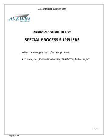
User GuideConfigurationMHM-97927-PBF2.3.2July 2020Main navigationThe main navigation page provides quick links to the Overview, Configure, and ServiceTools menus, as well as to other context menus available for the device.In the Device Explorer view, select the wireless network where the transmitter isconnected and right-click the transmitter to display the context menus.Figure 2-1: AMS Wireless Vibration Monitor Main NavigationMHM-97927-PBF, DRAFT25
ConfigurationUser GuideJuly 20202.3.3MHM-97927-PBFOverview menuThe Overview menu provides a glimpse of the status of the AMS Wireless VibrationMonitor, including the status of the connection to the wireless network, and a summary ofthe primary variables, machine temprerature, battery voltage, and update rate.You can also access the following shortcuts from this page: Device Information Perform Acquisition Join Device to NetworkDevice InformationThis window shows relevant device information such as the serial number, deviceidentifier, and revision numbers.26MHM-97927-PBF, DRAFT
User GuideConfigurationMHM-97927-PBFJuly 2020Identification—displays the device tag, long tag, device type, serial number, deviceidentifier, date, and device description.Revision Numbers—displays the universal, field device, software, hardware, and DDrevision numbers.MHM-97927-PBF, DRAFT27
ConfigurationUser GuideJuly 20202.3.4MHM-97927-PBFConfigure menuUse this menu to configure sensors, variable mappings, units and alert limits.You can select either Guided Setup or Manual Setup.ImportantTo be able to edit configuration settings, select Current in the Time drop-down menu atthe bottom of the screen.Guided SetupGuided Setup lets you configure device settings in a guided step-by-step process. Clickeach of the buttons under Initial Setup to complete the guided setup.Click Configure Variable Mapping to display or specify which measurements are reportedas the Primary, Secondary, Tertiary, and Quaternary variables.Click Configure Device Variable Units to configure units for device variables.Click Configure Alert Limits to define the lower range and upper range values and alertlimits for Advisory, Maintenance, and Failure for each of the process variables. You can alsoconfigure alert reporting from here.Click Configure Acquisition Settings to set the acquisiton settings.Click Join Device to Network to enter network identifiers and join keys that will enable thetransmitter to join a wireless network.Click Configure Update Rate to set how often the device acquires and reports newmeasurements (update rate) and to specify the number of times the transmitter skips dataacquisitions between updates to the gateway.28MHM-97927-PBF, DRAFT
User GuideConfigurationMHM-97927-PBFJuly 2020Manual SetupManual Setup lets you configure device settings manually.Click the Wireless tab to display wireless network information for the transmitter.Figure 2-2: Wireless tabClick Join Device to Network to enter network identifiers and join keys that will enable thetransmitter to join a wireless network.Click Configure Update Rate to set how often the device acquires and reports newmeasurements (update rate) and to specify the number of times the transmitter skips dataacquisitions between updates to the gateway (PowerSave Skip Multiplier).Click Apply Default Burst Configuration to reset the burst configuration to default values.MHM-97927-PBF, DRAFT29
ConfigurationUser GuideJuly 2020MHM-97927-PBFFigure 2-3: Machine Settings tabClick Configure Acquisiton Settings to configure the parameters for the specific sensor.Click Refresh Acquisition Settings to reset the parameters to default values.30MHM-97927-PBF, DRAFT
User GuideConfigurationMHM-97927-PBFJuly 2020Figure 2-4: General Settings tabClick Write Protect to allow or block an appliocation from modifying the deviceparameters.Click Allow Software Configuration to allow or block software appliocations to modify thedevice parameters.Click the Configure Device Variable Units to specify the units for measurement foracceleration, velocity, and temperature.Use this tab to set the country and timezone where the device is located.MHM-97927-PBF, DRAFT31
ConfigurationUser GuideJuly 2020MHM-97927-PBFFigure 2-5: Mapping tabUse this tab to set the primary, secondary, tertiary, and quarternary variables. You can setany of the device variables as process variables.Figure 2-6: Device Information tab32MHM-97927-PBF, DRAFT
User GuideConfigurationMHM-97927-PBFJuly 2020Figure 2-7: License tabClick Change License to change installed licenses.Figure 2-8: Alert SetupMHM-97927-PBF, DRAFT33
ConfigurationJuly 2020User GuideMHM-97927-PBFAlert Setup lets you configure the upper and lower range values and alarm limits for ZOverall, Z Peakvue, X Overall, Y Overall, Machine Temperature, Battery Voltage, Velocity,Acceleration, and Speed.For each of these pa
The AMS Wireless Vibration Monitor is an installation-ready solution that monitors vibration and temperature in rotating equipment in hard-to-reach locations. The AMS Wireless Vibration Monitor also provides a variety of monitor and sensor configurations. It has built-in radio and four integral sensors: X and Y MEMS