Transcription
PROJECT 07-03 JUNE 2012INTRODUCTIONAND OVERVIEWCONDUCTORCHARACTERISTICSGUYINGPRACTICES ANDPROCEDURESSIZINGTRANSFORMERAND SERVICEAPPENDICESPRACTICES ANDPROCEDURESPOLE STRENGTHJOINT USEAPPLICATIONBIBLIOGRAPHYCODES ANDSPECIFICATIONSSTRENGTH OFPOLE-TOPASSEMBLIESSTAKING FOR UNITPRICE CONTRACTSDESIGNING out the AuthorsLegal NoticeAddendum
appendicesAppendix A: Assembly Numbering, RUS Bulletin1728F-804, 7.2/12.5-kV SpecsAppendix B: Sag and Tension TablesAppendix C: Horizontal Pull and Total Guy Load atAngles for 30- to 55-Foot Poles UsingGrade C Construction
about the authorsKevin Mara, P.E.Kevin Mara is the Principal Engineer of Hi-Line Engineering. Mr. Mara’s mainareas of expertise are distribution system planning, power system modelingand analysis, overhead and underground distribution design. He has over25 years of experience as a distribution engineer and is registered as aProfessional Engineer in 17 states. Mr. Mara performs planning studies,general consulting, underground distribution design, territorial assistance,overcurrent protection schemes, sectionalizing studies, lightning protection,and training services. Mr. Mara received his Bachelor of Science ElectricalEngineering from Georgia Institute of Technology.Mr. Mara has developed course material for seminars on overhead distributiondesign, underground distribution design, overcurrent protection, NationalElectrical Safety Code, and the application of non-wood pole structures. Inaddition, he has conducted more than 50 training seminars from Florida toAlaska. More than 4,000 people have attended courses instructed by Mr.Mara. Mr. Mara has authored several publications including Field StakingInformation for Overhead Distribution Lines and four chapters of the TVPPATransmission and Distribution Standards and Specifications.Richard Lovelace, R.F.Mr. Lovelace is an Executive Consultant and retired Principal of Hi-LineEngineering. His main areas of expertise are overhead distribution design,underground distribution design, contract administration, work orderinspection, right-of-way easement acquisition, vegetation managementplanning, and system evaluation. Mr. Lovelace has over thirty years experiencein the operation and engineering of electric distribution systems. Mr. Lovelacereceived his degree B.S. Degree in Forestry from Auburn University and a B.S.Electrical Engineering from Kennedy Western University. He is also a CertifiedArborist and a Registered Forester in the states of Alabama and Georgia.continued
about the authors (cont .)Braxton J. Underwood, P.E.Mr. Underwood is a Project Manager at Hi-Line Engineering and has over 10years of experience in the power engineering/consulting. Mr. Underwood’sduties include underground and overhead distribution system design, aswell as system modeling, load flow analysis, sectionalizing, and overcurrentprotection.He has completed numerous RUS long range plans, constructionwork plans, substation justification studies, motor analyses, and systemmapping projects. Mr. Underwood has also authored or co-authored severalpublications including Streetlighting Best Practices for APPA and DistributionSystem Arc-Flash Calculation Case Studies for CRN/NRECA.Mr. Underwood received his Bachelor of Electrical Engineering degree fromAuburn University and he is a registered as a Professional Engineer in thestates of Alabama and Kansas.Robert C. Dew, Jr., P.E., Regional Manager, Hi-Line EngineeringMr. Dew has over 34 years of electrical engineering experience, primarily withelectric cooperatives. He is also registered as a Professional Engineer in 16states. In his career, Mr. Dew has prepared over 200 work plans, long rangeplans, and sectionalizing studies for cooperatives from Alaska to Florida. Mr.Dew is a longtime member of the IEEE Rural Power Committee and the NRECAT&D System Planning Subcommittee and is an NESC expert and frequentexpert witness in numerous electric contact cases and territorial affairs.Mr. Dew is currently a Regional Manager for Hi-Line Engineering andmanages Hi-Line Engineering’s Indiana Office.Mr. Dew has an MBA from Butler University and a BS Electrical Engineeringfrom Purdue University. He has also done Post Graduate Work in ElectricalEngineering at Georgia Institute of Technology.
PROJECT 07-03 JUNE 2012s
this page intentionally left blank
PROJECT 07-03Simplified Staking Manual forOverhead Distribution LinesFourth EditionPrepared byKevin J. Mara, P.E.W. Richard LovelaceHi-Line Engineering, LLC1850 Parkway Place, Suite 800Marietta, Georgiawww.hi-line-engineering.comforThe National Rural Electric Cooperative AssociationCooperative Research Network4301 Wilson BoulevardArlington, Virginia 22203-1860
The National Rural Electric Cooperative AssociationThe National Rural Electric Cooperative Association (NRECA), founded in 1942, is the national service organization supportingmore than 900 electric cooperatives and public power districts in 47 states. Electric cooperatives own and operate more than42 percent of the distribution lines in the nation and provide power to 40 million people (12 percent of the population).NRECA’s Cooperative Research Network (CRN) harnesses research and development to benefit its electric co-op members infour key ways: Improve productivityControl costsIncrease service excellenceKeep pace with emerging technologiesCRN strives to deliver new products and services best suited to the particular needs of electric co-ops. CRN communicates withits members through its Web site (www.cooperative.com/crn), online and printed reports, newsletters, Web conferences, andseminars.In addition, CRN staff present at several annual events, including NRECA’s TechAdvantage Conference & Expo, theNRECA/Touchstone Energy “Connect” marketing conference, and Touchstone Energy’s New & Emerging Technologies (NET)Conference. For more information about these events and CRN’s participation, visit the Conferences & Training section ofwww.cooperative.com. For questions about CRN, call 703.907.5843. Simplified Staking Manual for Overhead Distribution Lines—Fourth EditionCopyright 2012 by the National Rural Electric Cooperative Association.Reproduction in whole or in part strictly prohibited without prior written approval of the National Rural Electric CooperativeAssociation, except that reasonable portions may be reproduced or quoted as part of a review or other story about thispublication.Legal NoticeThis work contains findings that are general in nature. Readers are reminded to perform due diligence in applying thesefindings to their specific needs as it is not possible for NRECA to have sufficient understanding of any specific situation toensure applicability of the findings in all cases.Neither the authors nor NRECA assumes liability for how readers may use, interpret, or apply the information, analysis,templates, and guidance herein or with respect to the use of, or damages resulting from the use of, any information,apparatus, method, or process contained herein. In addition, the authors and NRECA make no warranty or representationthat the use of these contents does not infringe on privately held rights.This work product constitutes the intellectual property of NRECA and its suppliers, as the case may be, and containsConfidential Information. As such, this work product must be handled in accordance with the CRN Policy Statement onConfidential Information.QuestionsBrian Sloboda703.907.5689brian.sloboda@nreca.coop
Contents – iiicon t e n t sAcknowledgmentsAddendumUpdates to the Simplified Staking Manual for OverheadDistribution Lines—Fourth EditionxvxviiSection 1Introduction and OverviewPurposeOverviewSection 2Field Staking Practices and ProceduresExamination of Local ConditionsPractical Structure LocationStructure SelectionMechanics of StakingPreparation of DocumentsStaking Equipment, Materials, and Design Aids334661415Section 3Applicable Codes and SpecificationsNational Electrical Safety Code (NESC)RUS Specifications and DrawingsRUS List of Materials17173539Section 4Conductor CharacteristicsConductor Tension LimitsSpan SelectionConductor SagMaximum Allowable Span Based on the Separation of Conductors4141464955Section 5Pole StrengthNESC RequirementsPole SizeUltimate Resisting MomentMaximum Wind SpanUnguyed Line Angle PolesExtreme Wind Loading on Unguyed PolesExtreme Ice with Concurrent Wind Loading on Unguyed Poles5959606573818185Section 6Strength of Pole-Top AssembliesCrossarm AssembliesStrength of CrossarmPin- and Post-Type Insulator AssembliesMaximum Permissible Line Angle11189899097115
iv – ContentscontentsSection 7Guying Practices and ProceduresGuying SituationsForces That Make Guying NecessaryNESC RequirementsRUS RequirementsLine Angle GuyingDead-end GuyingTap GuyingGuying Calculations119119121124125131134138139Section 8Joint UseStrength RequirementsClearance RequirementsJoint-Use Construction on Different Utility Distribution LineCommunication or Cable TV Joint-Use Construction onExisting Cooperative Structures151151152153Section 9Staking for Unit Price ContractsAccuracyUnitsContract SpecificationsStaking SheetsStakesSample RUS Form 830 Contract Documents157157157159159159160Section 10Sizing Transformer and ServiceTransformer LoadingTransformer SizingVoltage LevelsVoltage Flicker from Starting MotorsMaximum Service LengthsVoltage Drop and Flicker Equations167167169171173174177Section 11ApplicationSingle-Phase Line Extension for Residential ServiceThree-Phase Line Extension for Industrial ServiceThe Staking Package179179183188154
Contents – vcon t e n t sSection 12Designing for Extra-Large ConductorsExtra-Large ConductorsSpansAnglesWeight SpansGuys and Anchors189189192197204207Appendix AAssembly Numbering, RUS Bulletin 1728F-804, 7.2/12.5-kV Specs213Appendix BSag and Tension Tables223Appendix CHorizontal Pull and Total Guy Load at Angles for 30- to 55-FootPoles Using Grade C Construction315Bibliography355Glossary357
v i – Il l u s t r a t i o n si l l u s t r a t .133.13.23.33.43.53.63.73.83.93.103.11PAGEUplift on StructureConductor UpliftRunning a Line Between Control Points Using a TransitLocation of Pole Stakes Using a Temporary Offset LineUse of Range Rods to Establish a Straight Line Between Control PointsMeasuring the Deflection Angle Using a TransitUse of a Surveyor’s Chain or Measuring Tape for Measuring aDeflection AngleUse of a Surveyor’s Chain or Measuring Tape for Bisecting aDeflection Angle180 Reverse Compass ScaleMeasuring and Bisecting a Deflection Angle with a HandCompassDetermination of Change in ElevationUplift FactorStaking of an Extended Vertical Angle 33.14Loading District MapWind Speed MapExtreme Ice Loading MapMinimum Vertical Clearance at Any Point in the SpanUnobstructed Climbing SpaceUnobstructed Working SpaceObstructed Climbing and Working SpaceApplication of Clearance TablesClearance Diagrams for Buildings and Other StructuresHorizontal Clearance with Wind DisplacementClearance Envelope for Grain Bins Filled by PermanentlyInstalled Augers, Conveyors, or ElevatorsClearance Envelope for Grain Bins Filled by Portable Augers,Conveyors, or ElevatorsDimensions of Components, Design Limits, and Bill of MaterialsPole Framing Guides4.14.24.34.4Two Spans Between Guyed Deadend StructuresSag and Tension Data Request FormSag (Catenary) CurveInclined Span Nomenclature485052555.15.25.35.4Wind Force on ConductorPole MomentWind SpanTransverse Loading on Structure616576773.1233333738
Illust r a t i o n s – v i iillustra t i o n sFIGUREPAGE6.16.26.36.4Weight SpanExamples of Longitudinal Unbalances on CrossarmsTypical Neutral AttachmentsPin Overload on C2 Pole-Top .2430 Line Angle with Bisect Guy60 Line Angle with Deadend Guys in Both DirectionsGuying Configuration for Crossing Span StructuresTransverse LoadingGuy Lead Ratios and Guy FactorsAverage Guy Attachment Height and Average Guy LeadLateral Deflection of Pole Due to Short Guy Lead and Vertical LoadSample Guy Attachment Strength Rating, E1-3 Guy AssemblyExpanding Anchor AssemblyPlate Anchor AssemblyCone Anchor AssemblyScrew Anchor AssemblySwamp Anchor AssemblyLog Anchor AssemblyRock Anchor AssemblyWind Span CalculationMultiple Anchor ConfigurationsSidewalk GuyGuying with Reduced-Tension SpansOverhead GuySpan Lengths and Deflection Angle for Example 7.7Guying Factor GraphWind Blowing Perpendicular to Tap LineWind Blowing Perpendicular to Tangent 331371371381391401461491508.1Midspan Vertical Clearance152
v i i i – Il l u s t r a t i o n si l l u s t r a t ionsFIGUREPAGE9.19.29.39.49.59.69.7An Example of Special Unit SpecificationCompleted Staking SheetSketch of LineRemoval Assembly Units ListNew Assembly Units ListSpecial Unit DescriptionsSpecial Drawing—Bog Shoe Assembly, M31, M31-115816016116216316416510.110.210.3Example of Load CycleAllowable Service VoltagesRange of Observable and Objectionable Voltage Flicker versus Time16817217311.111.2Line Extension, Single PhaseLine Extension, Three Phase180184
TaTablesb l e s –– iixxtablesTABLEPAGE2.1Typical Distribution Line Staking Table123.13.23.3NESC Loading District Ice and Wind LoadsHorizontal Wind Pressures on Cylindrical SurfacesGrades of Construction for Supply Conductors Alone, at Crossing,or on the Same Structures with Other ConductorsCommon Voltages of Cooperative Systems with AssociatedPhase-to-Ground VoltagesMinimum Basic Vertical Clearance at Supports Between Line ConductorsMinimum Vertical Clearance at Any Point in the Span fromDistribution Conductors to Underbuild ConductorsClearance Between Conductors Bounding the Climbing SpaceVertical Clearances of Wires, Conductors, and CablesAbove Ground, Rails, or WaterBasic Clearances of Conductors Passing by But Not Attachedto Buildings, Signs, or Other InstallationsBasic Vertical Clearances of Wires, Conductors, and CablesCarried on Different Supporting StructuresPhase and Neutral Clearances from Grain Bin1920NESC Tension Limits for ACSR ConductorRecommended Tension Limits for ACSR ConductorRecommended Tension Limits for AAAC ConductorAluminum Company of America Sag and Tension DataStringing Sag TableTime–Sag TableMaximum Allowable Final Unloaded Sag for Standard RUS AssembliesBased on NESC Rule 5.12Overload Capacity Factors for Wood StructuresExtreme Wind Overload Capacity Factors for Wood DistributionStructures When InstalledACSR Conductor Specifications with Transverse NESC District LoadingsRecommended Minimum Pole Class for One Transformer Installedon a Single PoleRecommended Minimum Pole Class for a Bank of Two TransformersInstalled on a Single PoleRecommended Minimum Pole Class for a Bank of Three TransformersInstalled on a Single PoleFiber Stress Ratings of PolesUltimate Resisting Moments of Wood PolesStrength Reduction Factors for Wood PolesBending Moment of Wood Poles at Groundline Due to Wind on PoleMaximum Wind Spans in Feet: Southern Yellow Pine & Douglas FirTransverse NESC District Loading on TV Cable22222425262830313456606062636364656669707378
x – Ta b l e stablesTABLEPAGE5.135.14Transverse NESC District Loading on Telephone CableExtreme Loading Coefficients for Wood Poles and Overhead Conductors78826.16.26.36.46.5Deadend Assemblies for Smaller ConductorsOverload Capacity Factors for Wood CrossarmsStrength Reduction Factors for Wood CrossarmsStrength of Pin- and Post-Type Insulator AssembliesRecommended Maximum Permissible Line Angle forPin-Type Pole-Top AssembliesMaximum Line AnglesOverload Capacity Factors for Support HardwareSine θ/2 for Line 110.2Average Guy Attachment Heights and Corresponding Guy Leadsfor Typical RUS Distribution StructuresLoad Factors (Overload Capacity Factors) for GuysGuy Wire Strength DataSoil Classification for Anchor DesignExample of Strength of Guy and Anchor AssembliesMedium Loading District—Three-Phase, 1/0 ACSR Primary and2 ACSR NeutralHorizontal Pull and Total Guy Load at DeadendsSine θ/2 for Line .610.710.8Ratings for Single-Phase Overhead Distribution TransformersDaily Peak Loads in Per Unit of Nameplate Rating to GiveMinimum 20-Year Life ExpectancyGuide for Sizing Single-Phase Overhead Distribution TransformersBased on Number of Homes ServedGuide for Estimating Load on Transformer Based on Numberof Homes ServedPractical Electrical Operating Characteristics of Residential Cooling UnitsSummary of Voltage Drop ConsiderationsMaximum Service Wire Lengths in Feet Based on Voltage Drop LimitsImpedance Values of 600-Volt Triplexed 18510.310.4Sag and Tension Data, 2 ACSR 6/1Initial Stringing Sag and Tension Table—2 ACSR 6/1Sag and Tension Data, 1/0 ACSRInitial Sag and Tension Table—1 ACSR169170171173174175178
TaTablesb l e s –– 9PAGEExtra-Large ConductorsSag Table for a 250-Foot Ruling Span of 795 ACSR under Heavy LoadingConductor Specifications with Transverse NESC District LoadingsMaximum Wind Spans in Feet: Southern Pine & Douglas FirMaximum Permissible Line Angle for Pin-Type Pole TopMaximum Line AnglesMaximum Weight Span Limited by Vertical Load on CrossarmsHorizontal Pull and Total Guy Load at Dead EndsHeavy Loading District: Three Phase—795 ACSR Primaryand 336 ACSR NeutralAppendix AAssembly Numbering, RUS Bulletin 1728F-804, 7.2/12.5-kV SpecsA.1From Bulletin 1728-F-804 Exhibit 3. Disposition of Assembliesin Bulletin 50-3 (D 804)Appendix BSag and Tension ading,4 ACSR, Ruling Span 250 Feet4 ACSR, Ruling Span 300 Feet4 ACSR, Ruling Span 350 Feet2 ACSR, Ruling Span 250 Feet2 ACSR, Ruling Span 300 Feet2 ACSR, Ruling Span 350 Feet1/0 ACSR, Ruling Span 250 Feet1/0 ACSR, Ruling Span 300 Feet1/0 ACSR, Ruling Span 350 Feet3/0 ACSR, Ruling Span 250 Feet3/0 ACSR, Ruling Span 300 Feet3/0 ACSR, Ruling Span 350 Feet4/0 ACSR, Ruling Span 250 Feet4/0 ACSR, Ruling Span 300 Feet4/0 ACSR, Ruling Span 350 Feet336 ACSR, Ruling Span 250 Feet336 ACSR, Ruling Span 300 Feet336 ACSR, Ruling Span 350 Feet477 ACSR, Ruling Span 250 Feet477 ACSR, Ruling Span 300 Feet477 ACSR, Ruling Span 350 Feet556 ACSR, Ruling Span 200 Feet556 ACSR, Ruling Span 250 Feet556 ACSR, Ruling Span 300 Feet740 AAAC, Ruling Span 200 Feet740 AAAC, Ruling Span 250 Feet740 AAAC, Ruling Span 300 247248249250251
x i i – Ta b l e B.75PAGELight Loading, 795 ACSR, Ruling Span 200 FeetLight Loading, 795 ACSR, Ruling Span 250 FeetLight Loading, 795 ACSR, Ruling Span 300 FeetMedium Loading, 4 ACSR, Ruling Span 250 FeetMedium Loading, 4 ACSR, Ruling Span 300 FeetMedium Loading, 4 ACSR, Ruling Span 350 FeetMedium Loading, 2 ACSR, Ruling Span 250 FeetMedium Loading, 2 ACSR, Ruling Span 300 FeetMedium Loading, 2 ACSR, Ruling Span 350 FeetMedium Loading, 1/0 ACSR, Ruling Span 250 FeetMedium Loading, 1/0 ACSR, Ruling Span 300 FeetMedium Loading, 1/0 ACSR, Ruling Span 350 FeetMedium Loading, 3/0 ACSR, Ruling Span 250 FeetMedium Loading, 3/0 ACSR, Ruling Span 300 FeetMedium Loading, 3/0 ACSR, Ruling Span 350 FeetHeavy Loading, 4/0 ACSR, Ruling Span 250 FeetHeavy Loading, 4/0 ACSR, Ruling Span 300 FeetHeavy Loading, 4/0 ACSR, Ruling Span 350 FeetHeavy Loading, 336 ACSR, Ruling Span 250 FeetHeavy Loading, 336 ACSR, Ruling Span 300 FeetHeavy Loading, 336 ACSR, Ruling Span 350 FeetHeavy Loading, 477 ACSR, Ruling Span 250 FeetHeavy Loading, 477 ACSR, Ruling Span 300 FeetHeavy Loading, 477 ACSR, Ruling Span 350 FeetHeavy Loading, 556 ACSR, Ruling Span 200 FeetHeavy Loading, 556 ACSR, Ruling Span 250 FeetHeavy Loading, 556 ACSR, Ruling Span 300 FeetHeavy Loading, 740 AAAC, Ruling Span 200 FeetHeavy Loading, 740 AAAC, Ruling Span 250 FeetHeavy Loading, 740 AAAC, Ruling Span 300 FeetHeavy Loading, 795 ACSR, Ruling Span 200 FeetHeavy Loading, 795 ACSR, Ruling Span 250 FeetHeavy Loading, 795 ACSR, Ruling Span 300 FeetHeavy Loading, 4 ACSR, Ruling Span 200 FeetHeavy Loading, 4 ACSR, Ruling Span 250 FeetHeavy Loading, 4 ACSR, Ruling Span 300 FeetHeavy Loading, 2 ACSR, Ruling Span 200 FeetHeavy Loading, 2 ACSR, Ruling Span 250 FeetHeavy Loading, 2 ACSR, Ruling Span 300 FeetHeavy Loading, 1/0 ACSR, Ruling Span 200 FeetHeavy Loading, 1/0 ACSR, Ruling Span 250 FeetHeavy Loading, 1/0 ACSR, Ruling Span 300 FeetHeavy Loading, 3/0 ACSR, Ruling Span 200 FeetHeavy Loading, 3/0 ACSR, Ruling Span 250 FeetHeavy Loading, 3/0 ACSR, Ruling Span 300 FeetHeavy Loading, 4/0 ACSR, Ruling Span 200 FeetHeavy Loading, 4/0 ACSR, Ruling Span 250 FeetHeavy Loading, 4/0 ACSR, Ruling Span 300 284285286287288289290291292293294295296297298299
Ta b l e s – x i i yAppendix CHorizontal Pull and Total Guy Load at Angles for30- to 55-Foot Poles Using Grade C ConstructionC.1C.2C.3C.4C.5C.6Light Loading District: Single Phase—4 ACSR Primary and NeutralLight Loading District: Single Phase—2 ACSR Primary and NeutralLight Loading District: Single Phase—1/0 ACSR Primary and NeutralLight Loading District: Three Phase—4 ACSR Primary and NeutralLight Loading District: Three Phase—2 ACSR Primary and NeutralLight Loading District: Three Phase—1/0 ACSR Primary and2 ACSR NeutralLight Loading District: Three Phase—3/0 ACSR Primary and1/0 ACSR NeutralLight Loading District: Three Phase—4/0 ACSR Primary and1/0 ACSR NeutralLight Loading District: Three Phase—336.4 ACSR Primary and4/0 ACSR NeutralLight Loading District: Three Phase—477.0 ACSR Primary and4/0 ACSR NeutralLight Loading District: Three Phase—556 ACSR Primary and336 ACSR NeutralLight Loading District: Three Phase—740 AAAC Primary and336 ACSR NeutralLight Loading District: Three Phase—795 ACSR Primary and336 ACSR NeutralMedium Loading District: Single Phase—4 ACSR Primary and NeutralMedium Loading District: Single Phase—2 ACSR Primary and NeutralMedium Loading District: Single Phase—1/0 ACSR Primary and NeutralMedium Loading District: Three Phase—4 ACSR Primary and NeutralMedium Loading District: Three Phase—2 ACSR Primary and 40740740795795795ACSR, Ruling Span 200 FeetACSR, Ruling Span 250 FeetACSR, Ruling Span 300 FeetACSR, Ruling Span 200 FeetACSR, Ruling Span 250 FeetACSR, Ruling Span 300 FeetACSR, Ruling Span 200 FeetACSR, Ruling Span 250 FeetACSR, Ruling Span 300 FeetAAAC, Ruling Span 200 FeetAAAC, Ruling Span 250 FeetAAAC, Ruling Span 300 FeetACSR, Ruling Span 200 FeetACSR, Ruling Span 250 FeetACSR, Ruling Span 300 333
x i v – Ta b l e Medium Loading District: Three Phase—1/0 ACSR Primary and2 ACSR NeutralMedium Loading District: Three Phase—3/0 ACSR Primary and1/0 ACSR NeutralMedium Loading District: Three Phase—4/0 ACSR Primary and1/0 ACSR NeutralMedium Loading District: Three Phase—336.4 ACSR Primary and4/0 ACSR NeutralMedium Loading District: Three Phase—477.0 ACSR Primary and4/0 ACSR NeutralMedium Loading District: Three Phase—556 ACSR Primary and336 ACSR NeutralMedium Loading District: Three Phase—740 AAAC Primary and336 ACSR NeutralMedium Loading District: Three Phase—795 ACSR Primary and336 ACSR NeutralHeavy Loading District: Single Phase—4 ACSR Primary and NeutralHeavy Loading District: Single Phase—2 ACSR Primary and NeutralHeavy Loading District: Single Phase—1/0 ACSR Primary and NeutralHeavy Loading District: Three Phase—4 ACSR Primary and NeutralHeavy Loading District: Three Phase—2 ACSR Primary and NeutralHeavy Loading District: Three Phase—1/0 ACSR Primary and2 ACSR NeutralHeavy Loading District: Three Phase—3/0 ACSR Primary and1/0 ACSR NeutralHeavy Loading District: Three Phase—4/0 ACSR Primary and1/0 ACSR NeutralHeavy Loading District: Three Phase—336.4 ACSR Primary and4/0 ACSR NeutralHeavy Loading District: Three Phase—477.0 ACSR Primary and4/0 ACSR NeutralHeavy Loading District: Three Phase—556 ACSR Primary and336 ACSR NeutralHeavy Loading District: Three Phase—740 AAAC Primary and336 ACSR NeutralHeavy Loading District: Three Phase—795 ACSR Primary and336 ACSR 48349350351352353354
Acknowled g m e n t s – x vacknowledgm e n t sThis simplified manual on the techniques ofstaking distribution lines is the culmination ofcountless hours of effort by many fine individuals. The manual is now in its third edition,which proves its value to our industry as areference book and a learning tool.The dedication of the lead author, W. RichardLovelace of Hi-Line Engineering, LLC, to this project made this manual a reality. His diverse experiences as a lineman, staking engineer, and aninstructor were invaluable to this project. KevinMara, P.E., provided input and direction to theoriginal edition. He also managed the subsequent revisions with assistance from MathewPamperin, Braxton Underwood, and Linda Gray.The original undertaking to create this manualwas managed by Robert C. Dew, Jr., P.E., withvaluable technical support provided by JohnA. Rodgers, P.E., Linda Gray, and Joe L.Thebeau.
this page intentionally left blank
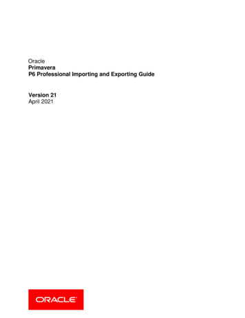
Addendum: Updates to the Simplified Staking Manual for Overhead Distribution Lines—Fourth Edition – xviiAAddendum:Updates to the Simplified StakingManual for Overhead DistributionLines—Fourth EditionThe Third Edition of the Simplified Staking Manual for Overhead Distribution Lines has been updatedbased on changes contained in the 2012 National Electric Safety Code (NESC). The goal of this FourthEdition is to be compliant with the current version of the NESC. This Addendum serves as a catalog ofthese changes, and also includes corrections to several typographical errors.1. Page 2, left column, first paragraph. The reference to the website was changed fromwww.usda.gov/rus to www.rurdev.usda.gov/UEP HomePage.html.2. Page 2, left column, third paragraph. After the sentence, “The third edition is based on the2007 NESC,” the following sentence was added:This fourth edition is based on the 2012 NESC.3. Page 2, right column, second full paragraph. “2007 NESC” was changed to “2012 NESC.”4. Page 18, right column. The following paragraph was added to the end of the subsection entitled“NESC LOADING DISTRICTS (250)”:In 2012, the NESC added a fourth loading zone to address the weather conditions on islandssuch as American Samoa, Guam, Hawaii, Puerto Rico, and the Virgin Islands. To apply theloading zone for the islands, it is recommended that the Light Loading (Zone 3)be used for facilities located between sealevel and 9,000 feet. For facilities onislands with an elevation of more than9,000 feet above sea level, use theMedium Loading District (Zone 2).Zone 15. Page 18. Figure 3.1 has been updated toshow the change to the loading zone forHawaii.6. Page 20, right column, bottom of the secondfull paragraph. The following sentence hasbeen added:Extreme ice loading does not apply towarm islands, such as Hawaii andAmerican Samoa.Zone 2Zone 3Alaska – HeavyHawaii – Light for elevations below 9,000 feetHawaii – Medium for elevations above 9,000 feetFIGURE 3.1: Loading District Map.
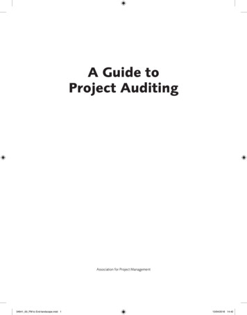
x v i i i – Addendum: Updates to the Simplified Staking Manual for Overhead Distribution Lines—Fourth EditionA7. Page 21, right column, second full paragraph. “Note 2” has been changed to “Note 1.”8. Page 22. Table 3.3 has been replaced with the following table. The 2012 NESC made significantchanges to Table 242, prompting this change.TABLE 3.3: Grades of Construction for Supply Conductors Alone, at Crossing, or on the SameStructures with Other ConductorsThe information provided in this table applies only to effectively grounded circuits and two-wire grounded circuits. Voltagesshown are phase-to-ground values. The grade of construction for supply conductors, as indicated across the top of the table,must also meet the requirements for any lines at lower levels except, when otherwise noted.Supply conductorsat higher levelsConductors, tracks,and rights-of-wayat lower levelsConstant-potential supply conductors0 – 0.75 kV0.75 – 22 kVOpen or CableOpenCableCommon or publicrights-of-wayCCCRailroad tracks, limitedaccess highways, andnavigable waterwaysrequiring waterway permitsBBBSupply conductors0 to 750 VOpen or cableCCC750 V to 22 kVOpen or cableCCCExceeding 22 kVOpen or cableBBBCommunication conductorOp
The National Rural Electric Cooperative Association The National Rural Electric Cooperative Association (NRECA), founded in 1942, is the national service organization supporting more than 900 electric cooperatives and public power districts in 47 states. Electric cooperatives own and operate more than