Transcription
LIGHT GAUGE STRUCTURAL FRAMING & ACCESSORIES05400105400
BUILDSTRONGLIGHT Gauge STRUCTURAL FRAMING & ACCESSORIESwww.TellingIndustries.com2
LIGHT GAUGE STRUCTURAL FRAMING & ACCESSORIESTABLE OF CONTENTSProduct Identification . . . . . . . . . . . . . . . . . . . . . . . . . . .4Floor Joist Span Tables . . . . . . . . . . . . . . . . . . . . . . . . . . 38 - 45General Product Information . . . . . . . . . . . . . . . . . . . . . . . 4 - 5Allowable Floor Joist Span Table Notes . . . . . . . . . . . . . . . . 43Material Specifications. . . . . . . . . . . . . . . . . . . . . . . . . . . . . . . 4Allowable Floor Joist Spans . . . . . . . . . . . . . . . . . . . . . . . . . 38 - 43Technical Assistance . . . . . . . . . . . . . . . . . . . . . . . . . . . . . . . . 4Floor Assembly Details . . . . . . . . . . . . . . . . . . . . . . . . . . . . . 44 - 45Thickness— Steel Components . . . . . . . . . . . . . . . . . . . . . . . 4Ceiling Span Table . . . . . . . . . . . . . . . . . . . . . . . . . . . . . . 46 - 47Design Stiffening Lip Length . . . . . . . . . . . . . . . . . . . . . . . . . . 4Ceiling Span Table Notes. . . . . . . . . . . . . . . . . . . . . . . . . . . . 46General Notes for all Tables. . . . . . . . . . . . . . . . . . . . . . . . . . .4Ceiling Spans— L/240. . . . . . . . . . . . . . . . . . . 46Definitions of Symbols. . . . . . . . . . . . . . . . . . . . . . . . . . . . . . . 4Physical Properties. . . . . . . . . . . . . . . . . . . . . . . . . . . . . . . 6Physical Properties Table Notes . . . . . . . . . . . . . . . . . . . . . . . 6Non-Structural Stud Physical Properties. . . . . . . . . . . . . . . . . 6Non-Structural Track Physical Properties . . . . . . . . . . . . . . . . 7Structural Stud Physical Properties. . . . . . . . . . . . . . . . . . . . . 8 - 9Structural Track Physical Properties . . . . . . . . . . . . . . . . . . . . 10 - 13Limiting Wall Height Tables . . . . . . . . . . . . . . . . . . . . . . . 14Limiting Wall Heights Non-Structural . . . . . . . . . . . . . . . . . . 14 - 15Wall Height Non-Structural Table Notes . . . . . . . . . . . . . . . . 14Limiting Wall Heights Structural. . . . . . . . . . . . . . . . . . . . . . . 16 - 19Wall Height Structural Table Notes . . . . . . . . . . . . . . . . . . . . 16Curtain Wall Construction Details . . . . . . . . . . . . . . . . . . . . . 20 - 21Axial Load Tables . . . . . . . . . . . . . . . . . . . . . . . . . . . . . . . 22 - 33Allowable Axial Load Table Notes . . . . . . . . . . . . . . . . . . . . . 22Allowable Axial Loads . . . . . . . . . . . . . . . . . . . . . . . . . . . . . . 22 - 33Construction Details . . . . . . . . . . . . . . . . . . . . . . . . . . . . . . . 34Web Crippling Load Tables . . . . . . . . . . . . . . . . . . . . . . . 35 - 37Ceiling Spans— L/360 . . . . . . . . . . . . . . . . . . 47Channel Properties. . . . . . . . . . . . . . . . . . . . . . . . . . . . . . 48 - 49(CRC) Cold-Rolled Channel Physical Propertiesand Allowable Span Tables . . . . . . . . . . . . . . . . . . . . . . . . . . 48(DWFC) Drywall Furring Channel Physical Propertiesand Allowable Span Tables . . . . . . . . . . . . . . . . . . . . . . . . . . 49Header Load Tables . . . . . . . . . . . . . . . . . . . . . . . . . . . . . 50 - 53Header Load Table Notes . . . . . . . . . . . . . . . . . . . . . . . . . . . 50Header Allowable Uniform Loads . . . . . . . . . . . . . . . . . . . . . 50 - 53Fastening Systems. . . . . . . . . . . . . . . . . . . . . . . . . . . . . . 54Screw Table Notes. . . . . . . . . . . . . . . . . . . . . . . . . . . . . . . . . 54Allowable Loads for Screw Connections . . . . . . . . . . . . . . . 53Weld Table Notes. . . . . . . . . . . . . . . . . . . . . . . . . . . . . . . . . . 53Allowable Loads for FilletWelds and Flare GrooveWelds . . 53Powder Systems . . . . . . . . . . . . . . . . . . . . . . . . . . . . . . . . . . 54Accessories . . . . . . . . . . . . . . . . . . . . . . . . . . . . . . . . . . . 55 - 56(CLT) Custom Leg Track, (FS) Flat Strapping ,Web Crippling Load Table Notes. . . . . . . . . . . . . . . . . . . . . . 35 - 36(WS) Web Stiffeners, (BC) Bridge Clip. . . . . . . . . . . . . . . . . . 55Web Crippling Conditions . . . . . . . . . . . . . . . . . . . . . . . . . . . ip.56AllowableWeb Crippling Loads— Single Members . . . . . . . 36Architectural Specification . . . . . . . . . . . . . . . . . . . . . . . . .37305400
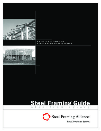
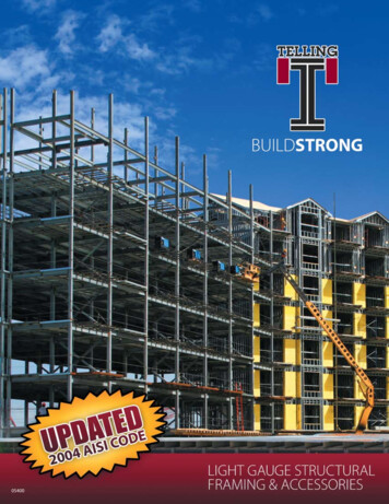
BUILDSTRONGPRODUCT IDENTIFICATIONSECTION PROPERTIESPRODUCT IDENTIFICATIONAll Telling Industries products contain a four part identification code. This identifies the size (both depth and flange/leg height), style, andmaterial thickness of each member.EXAMPLE:MATERIAL THICKNESS:(Example: 0.054 in. 54 mils 16 gauge; 1 mil 1/1000 in.)Material thickness is the minimum base metal thickness inmils. Minimum base metal thickness represents 95% of thedesign thickness.WEB DEPTH:(Example: 6” 600 x 1/100 inches) Allmember depths are taken in 1/100 inches.For all “T” sections member depths is theinside to inside dimension.600S16254FLANGE/LEG HEIGHT:(Example: 1 5/8” 1.625” 162 x 1/100 inches)All flange widths are taken in 1/100 inches.STYLE:(Example: Stud or Joist section S)The two alpha characters utilized by theidentification code are:S Stud or Joist SectionsT Track SectionsNote: For those sections where two different yield strengths (33 ksi and 50 ksi) are shown, the yield strength used in the design, if greater than 33 ksi,should be identified on the design and ordering of steel. (i.e., 600S162-54(50 ksi)THICKNESS - STEEL COMPONENTSDESIGN STIFFENING LIP sideCorner Radii(in)Reference OnlyGauge ngSectionFlange WidthDesign StiffeningLip Length (in)25MillS1251 1/4”0.18822BlackS1371 3/8”0.3750.078120 - DrywallWhiteS1621 5/8”0.50.03460.076420 - S2502 130.106914Orange970.10170.152512Red1Minimum Thickness represents 95% of the design thickness and is the minimum acceptable thickness delivered to the job site based on Section A2.4 of the 2004 NASPEC.www.TellingIndustries.com4
LIGHT GAUGE STRUCTURAL FRAMING & ACCESSORIESGENERAL PRODUCT INFORMATIONRAW MATERIAL INFORMATIONAll Telling Industries products are formed fromsteel with a minimum yield strength of 33 or50 KSI (1000 lbs per square inch). All productscontained in this brochure are engineered tomeet the 2001 Edition of the AISI (American Ironand Steel Institute) North American Specificationfor the Design of Cold- Formed Steel StructuralMembers. The same document was used tocalculate the physical and structural propertiesof all products listed herein via allowable stressdesign criteria.TECHNICAL ASSISTANCETechnical assistance is available to TellingIndustries customers when requested. A TellingIndustries representative or design professionalcan review project specific load conditionsand determine deflection criteria and lateralbracing conditions not discussed herein. Further,our representatives can assist purchasersand designers in economical applications formaximum efficiency.GENERAL NOTES FOR ALL TABLES1. The strength increase due to cold workforming was incorporated for flexural strengthas applicable per AISI A7.2.DEFINITIONS OF STRUCTURAL PROPERTY SYMBOLS2. The moment of inertia for deflection iscalculated at a stress which results in aneffective section modulus such that thestress times that section modulus is equal tothe allowable moment. This follows Procedure1 of the AISI specification.3. The yield stresses (33 ksi or 50 ksi) used tocalculate the tabulated values are indicated inthe tables.4. When provided, factory punch-outs will belocated along the centerline of the webs ofthe members and will have a minimum center to-center spacing of 24”. Punch-outs will havea maximum width half the member webheight (d/2) or 1 1/2”, whichever is less, anda maximum length 4”. The minimumdistance between the end of the member andthe near edge of the web punch-out 10unless otherwise specified.5. For those steels that have both 33 and 50 ksilistings, if the design is based upon 50 ksi, the50 ksi steel needs to be specified by thedesigner/purchasers. (i.e., 362S137- 54 (50 ksi)All information contained in this brochure isintended as a general guide for using TellingIndustries’ products. This information shouldnot be used in design or assembly without anindependent assessment by a qualified designprofessional. Such an assessment is necessary toverify the suitability of a particular product for usein any load bearing application. Telling Industriesassume no liability for failure resulting fromthe use or misapplications of any informationcontained herein. Detail drawings containedherein are for information only. Telling Industriesreserve the right to make modifications, changes,additions or deletions to the information onany of our products without prior notice orobligation. For the latest product information orto verify availability, contact a Telling Industriesrepresentative. This brochure contains the latestinformation available at the time of printing.GROSS PROPERTIESIxx: Moment of inertia of the gross sectionabout the X-X axis (strong axis).TORSIONAL PROPERTIESJ: St. Venant Torsional Constant.Rx: Radius of gyration of the gross sectionabout the X-X axis.Xo: Distance from the shear center to thecentroid along the principal X-axis.Iyy: Moment of inertia of the gross sectionabout the Y-Y axis (weak axis).Ry: Radius of gyration of the gross sectionabout the Y-Y axis.EFFECTIVE PROPERTIESIxx: Moment of inertia for deflectioncalculations based on the “Procedure 1or Deflection Determination” of the 2001AISI Specification.Sxx: Effective section modulus about the X-Xaxis (strong axis) Stress FyMa: Allowable Bending Moment- Based onthe effective section modulus and theallowable stress including the strengthincrease from cold-work of forming(AISI A 7.2) where applicable.Cw: Torsional warping constant.Ro: Polar radius of gyration about the centroidprincipal axis.ß: 1- (Xo/Ro)2SECTION PROPERTIES TABLE NOTES1. The centerline bend radius is the greater of2 times the design thickness or 3/32”.2. Web depth for track sections is equal tothe nominal height plus 2 times the designthickness plus the bend radius.3. Hems on non-structural track sectionsare ignored.4. Effective properties incorporate thestrength increase from the cold work offorming as applicable per AISI A7.2.5. Tabulated gross properties are based onthe full-unreduced cross section of thestuds, away from punch-outs.Va: Allowable Shear Load.6. For deflection calculations, use the effectivemoment of inertia.Ycg: Maximum distance from the outside of thecompression flange to the center of gravityof the effective section.7. For those steels that have both 33 and 50ksi, the 50 ksi steel needs to be specified.(I.e., 362S137-54 (50 ksi))505400
BUILDSTRONGPHYSICAL PROPERTIESNON-STRUCTURAL STUD PHYSICAL PROPERTIESDesignGross Properties33 ksi Effective Properties50 ksi Effective PropertiesTorsional 050-0.5012.8320.969Section Property Table Notes1.2.3.4.5.6.7.8.Web depth for track sections equals nominal depth plus 2 x design thickness plus bend radiusHems on non-structural track sections are ignoredEffective properties include the strength increase from cold-work of forming per NASPEC section A7.2 where applicableTabulated gross properties are based on the full, unreduced section away from punchoutsEffective properties of all ‘S’ sections based on punched sections. Track sections are considered unpunchedFor deflection determination, use the effective moment of inertia. Effective moment of inertia is based on Procedure 1 of the NASPEC.For sections with properties listed for both 33 ksi and 50 ksi yield point, the required yield point should be specified in the design documentsWhere effective properties are not listed for a section at 33 or 50 ksi yield, web depth-to-thickness or flange width-to-thickness limits from the NASPEC are exceeded. Only grossproperties are available.9. Where section designations include a superscript ‘1’, web height-to-thickness exceeds 200. Web stiffeners are required at all supports and concentrated loads.www.TellingIndustries.com6
LIGHT GAUGE STRUCTURAL FRAMING & ACCESSORIESPHYSICAL PROPERTIESNON-STRUCTURAL TRACK PHYSICAL oss (in4)0.0500.0570.0660.0550.0620.07233 ksi Effective 0-27362T200-30362T200-33Torsional 50.4760.3910.3940.3950.395Note: 1 Web height-to-thickness ratio exceeds 200. Web stiffeners required at all supports and concentrated loads.705400
BUILDSTRONGPHYSICAL PROPERTIESSTRUCTURAL STUD PHYSICAL 1Gross (in4)0.2030.2610.3180.3860.2350.3020.3700.4533 ksi Effective 39.9312.
DESIGN STIFFENING LIP LENGTH Section Flange Width Design Stiffening Lip Length (in) S125 1 1/4” 0.188 S137 1 3/8” 0.375 S162 1 5/8” 0.5 S200 2” 0.625 S250 2 1/2” 0.625 S300 3” 0.75 1Minimum Thickness represents 95% of the design thickness and is the minimum acceptable thickness d