Transcription
THE UNOFFICIAL GLOCK ARMORER’S MANUALCompiled by John Hisghman
THE UNOFFICIAL GLOCK ARMORER’S MANUALTABLE OF CONTENTSThe Unofficial Glock Armorer’s ManualComplied by John HisghmanOctober 1999Section NamePage Numbers1. Identification of Various Glock Parts32. Exploded Schematic of a Glock Pistol with Parts List43. Glock Field Strip Disassembly5-84. Cleaning the Field Stripped Firearm95. Lubrication Points106. Slide Disassembly and Firing Pin Replacement11-147. Firing Pin Safety Check158. Glock Receiver Disassembly16-199. Stock and New York Trigger Installation2010. Glock Magazine Disassembly2111. Magazine Catch Removal2212. Notes and Records2313. Close Quarters Combat - The Solution24-2814. Human Reaction Time On The Outcomes CQC29-31Special Thanks to Glockmeister.com2
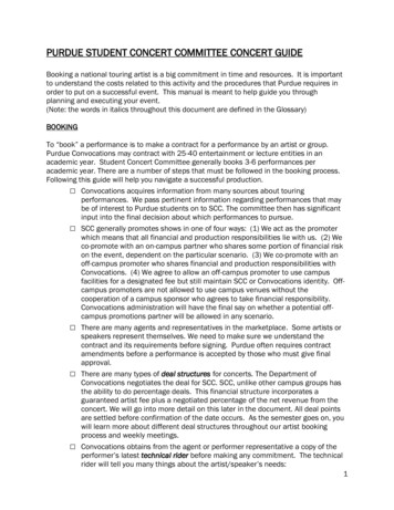
THE UNOFFICIAL GLOCK ARMORER’S MANUALConnector IdentificationTrigger DiagramMagazine Identification3
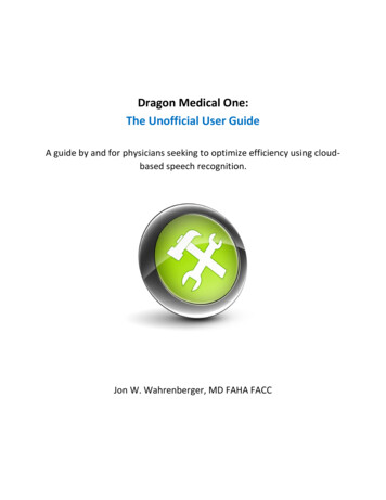
THE UNOFFICIAL GLOCK ARMORER’S MANUAL1. Slide2. Barrel3. Recoil spring assembly4. Recoil spring assembly5. Firing pin6. Spacer sleeve7. Firing pin spring8. Spring cups9. Firing pin safety10. Firing pin safety spring11. Extractor12. Extractor depressor plunger13. Extractor depressor plunger spring14. Spring-loaded bearing15. Slide cover plate16. Rear sight16a.Front sight17. Receiver18. Magazine catch spring19. Magazine catch20. Slide lock spring21. Slide lock22. Locking block23. Trigger mechanism housing with ejector24. Connector25. Trigger spring25a. New York Trigger spring 125b. New York Trigger spring 226. Trigger with Trigger bar27. Slide stop lever28. Trigger pin29. Trigger housing pin30. Follower31. Magazine spring32. Magazine floor plate32a. Magazine insert33. Magazine tube34. Locking block pin:(mod. G18/20/21/22/23/24/25/26/27/28/29/30/31/32/33/35)4
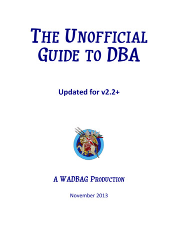
THE UNOFFICIAL GLOCK ARMORER’S MANUALTHE GLOCK FIELD STRIP DISASSEMBLYFor normal cleaning, it is sufficient to dismantle the pistol into its main componentparts (see above graphic): SlideBarrelRecoil Spring AssemblyReceiverMagazine1. Glock pistols are stripped into their component parts in the following order:1.2.3.4.Remove MagazineDepress TriggerRemove SlideRemove Barrel5
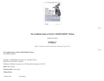
THE UNOFFICIAL GLOCK ARMORER’S MANUAL2. Remove the magazine (Fig. 1)3. Check for round in the chamber (Fig. 2 - repeat three times for safety)4. Depress trigger (Fig. 3 - pointing in a safe direction)6
THE UNOFFICIAL GLOCK ARMORER’S MANUAL5. Remove slide from receiver Grasp the pistol in the right or left hand in such a way that four fingers rest over theslide and the thumb rests on the rear side of the receiver (Fig. 4 - make an O.K. withyour hand and slip the beaver tail and end of the slide through the palm side of theO.K. hole) Using the fingers draw back the slide no more than 1/16" (Fig. 5 - if you pull the slideback too far - you will need to rack the slide, pull the trigger and repeat this step). Pull the slide lock downward with the thumb and index finger of the free hand (Fig. 5 pull both tabs down at once to the bottom of the groove). While holding the slide lock tabs down, push the slide forward and separate it fromthe receiver (Fig. 5 & 6).7
THE UNOFFICIAL GLOCK ARMORER’S MANUAL6. Removal of the barrel: Push the recoil spring assembly somewhat forward with the thumb and raise it(caution spring is under tension). Remove recoil spring assembly from the slide. Grasp the barrel on the barrel locking lugs, lift and push it slightly forward, raise andpull back out of the slide.7. Reassembly of the Glock pistol: Carry out the above instructions in reverse order (although it is not necessary to pulldown the tabs on the slide lock).8
THE UNOFFICIAL GLOCK ARMORER’S MANUALCLEANING THE FIELD STRIPPED FIREARMThe Glock pistol should be cleaned after each shooting session. Once field stripped,the barrel and chamber are easily cleaned from the chamber end. The inside of the slideand receiver should be wiped clean along with the outside of the barrel. We suggest one ofthe many quality non-toxic solvents that are available in today’s gun cleaning market. Thiswill ensure proper functioning of your Glock pistol.As with any semi-automatic pistol, Glock pistols should not be cleaned by merelylocking the slide to the rear and inserting the cleaning rod from the muzzle end. This cancause excessive amounts of solvents to build-up in both the receiver, slide and possiblycontribute to malfunctions of the pistol. The pistol should be field stripped every time it iscleaned.DO NOT CLEAN THE GLOCK FROM THE MUZZLE END1. The inside of both the chamber and the barrel should be wiped completely dry oncethey have been thoroughly cleaned. The breech face and the area under theextractor claw should both be absolutely dry and free of any debris after cleaning.2. The slide rail cuts should be cleaned thoroughly by using a clean patch on the end ofa toothbrush-type cleaning tool.3. With the clean patch wrapped over the brush portion of the toothbrush, thoroughlyclean the slide rail cuts of all debris and solvents.4. All other areas of the slide and receiver should be checked for cleanliness. Mostparts in the receiver may be wiped with a clean, soft cloth.5. After the parts in the receiver have been cleaned, they should be wiped dry with aclean, soft cloth. All solvents should be wiped from the parts so the parts are cleanand dry,6. Note: 6" cotton tipped applicators (wooden stems) by Patterson Dental Company canget into the corners and hard to get at areas. The wooden tip is great to clean out theslide rail cuts. Q-Tip style cotton swabs also work well.THE GLOCK DOES NOT REQUIRE EXCESSIVE LUBRICATION.PLEASE REFER TO THE LUBRICATION SECTION TO SEE DETAILED INSTRUCTIONS9
THE UNOFFICIAL GLOCK ARMORER’S MANUALLUBRICATION POINTSOnly Lubricate the Glock according the diagram below:DO NOT OVER-LUBRICATE THE GLOCK10
THE UNOFFICIAL GLOCK ARMORER’S MANUALSLIDE DISASSEMBLY / FIRING-PIN REPLACEMENTSAFETY CAUTION:The firing pin assembly and extractor depressor plunger are undertension. While removing the slide cover plate, place your thumb over thefiring pin assembly and extractor depressor plunger to prevent theseparts from ejecting while removing the slide cover plate.11
THE UNOFFICIAL GLOCK ARMORER’S MANUAL1. To aid in the removal of the slide cover plate, place the muzzle end of the slide on asmooth, flat surface such as a table. Keep the slide in and upright position whileapplying firm downward pressure on the slide. With your free hand use your Glockdisassembly tool to push the spacer sleeve forward (see figures 1 & 2).2. Simultaneously, slide the cover plate down and off (Figure 3) - remember to keep thetensioned firing pin assembly and extractor depressor plunger from springing out. It ispossible that the slide cover plate will require some additional downward force duringdisassembly of a new pistol. A thin bladed screwdriver may be used to start removal(don't force it).12
THE UNOFFICIAL GLOCK ARMORER’S MANUAL3. Remove the firing pin assembly (figure 4).4. Remove the extractor depressor plunger assembly (figure 5) consisting of: extractordepressor plunger, extractor depressor plunger spring and the spring loaded bearing.5. While depressing the firing pin safety, remove the extractor (figures 6 & 7). Theextractor may need to be pushed from the extractor groove by using your Glockdisassembly tool in the rear of the extractor and lifting the extractor from the groove.13
THE UNOFFICIAL GLOCK ARMORER’S MANUAL6. Remove the firing pin safety (figure 8). If the safety does not drop out of the slide; theslide may be tapped on a non-metallic surface to free the firing pin safety. Be carefulnot to lose the firing pin safety spring when removing the safety.Before you disassemble the firing pin assembly, wipe the assembly with a clean drycloth to remove any excess lubrication or solvent.7. Pull down on the firing pin spring with the thumb and forefinger as far as possible toallow clearance for removal of the firing pin spring cups. Be sure to keep a firm graspon the firing pin spring so that it does not launch itself and possibly cause injury orbecome lost. Simultaneously remove the two spring cups, then gradually releasetension on the firing pin spring and remove it (figure 9). Now you can remover thespacer sleeve.8. When reassembling the firing pin assembly, ensure that the small ends of the springcups are inside the firing pin spring. Reverse all procedures for reassembly.9. Remember To Do A Firing Pin Safety Check After This Procedure.14
THE UNOFFICIAL GLOCK ARMORER’S MANUALGLOCK FIRING PIN SAFETY CHECKMake sure that the firing pin safety is properly engaged by pulling the tang of thefiring pin toward the rear of the slide (do not allow the firing pin to snap forward - ease itforward). Next, hold the slide in the palm of your hand, sights down, with your thumbpushing the tang of the firing pin forward. The firing pin should not protrude from the firingpin hole. If it does, the firing pin and firing pin safety should be replaced.Assuring the firing pin is released by the firing pin safety:Method OneFirst make sure the firing pin safety is engaged and then hold the slide in a MuzzleDown position and depress the firing pin safety. The tip of the firing pin should moveforward and be visible protruding from the firing pin hole. The firing pin may need tobe pushed forward when the pistol is new, so that it will protrude from the firing pinhole.Method TwoDepress the firing pin safety and shake the slide. When the firing pin safety isdepressed, the firing pin should be heard moving freely. When the firing pin safety isnot depressed, the firing pin should be nearly silent.The above information is only being presented as general information.Please note that there could be more wrong with a firing system in a Glock than is outlined above.If you are having problems with your firing system, consult a qualified Glock Armorer.Maintenance should not be performed by anyone other than a Glock Certified Armorer.15
THE UNOFFICIAL GLOCK ARMORER’S MANUALRECEIVER DISASSEMBLYAFTER FIELD STRIPPING THE GLOCK:1. Grasp the front portion of the receiver and remove the locking block pin with your3/32" disassembly tool (see figure 1). Older models 17, 17L and 19 do not have alocking block pin, so skip the above step for these models. Remember the lockingblock pin is the first pin to be removed and the first pin to be reinstalled. If you installthe locking block pin after you install the slide stop lever, you will bend and damagethe slide stop lever spring.2. Next, remove the trigger pin. To facilitate trigger pin removal, the slide stop levershould be moved forward and rearward while applying pressure on the trigger pin(see figure 2). DO NOT use any excessive force (such as a hammeringimplement) to remove the trigger pin. This will unhook the slide stop lever springfrom the groove in the trigger pin. Remember to remove it from left to right!16
THE UNOFFICIAL GLOCK ARMORER’S MANUAL3. With the trigger pin removed, withdraw the slide stop lever by pulling it back and out(see figure 3.). NOTE: When reinstalling the slide stop lever in the pistol, be sure itlocks into the grove in the trigger pin. To function check the slide release lever, lift itfrom its rest position and release it. It should snap back into position crisply. If it failsto do so, make sure the spring is not binding or bent and check to make sure theslide stop release is riding in the groove in the trigger pin.4. With the locking block pin and trigger pin removed, use your disassembly tool to raisethe locking block (see figure 4). Note: Pry up from the left side of the locking block toavoid damaging the trigger bar.17
THE UNOFFICIAL GLOCK ARMORER’S MANUAL5. Now move to the rear of the gun and use your disassembly tool to push the triggerhousing pin out (see figure 5). Remove the trigger-housing pin.6. With the trigger housing pin removed use your disassembly tool to apply pressureunder the ejector to raise the complete trigger assembly from the receiver (see figure6). Then raise the rear most portion of the trigger assembly above the receiver andwithdraw the complete assembly (see figure 7).18
THE UNOFFICIAL GLOCK ARMORER’S MANUAL7. Next comes the trigger assembly takedown. Hold the trigger assembly as shown infigure 8. Pull forward on the trigger with the trigger bar while rotating the trigger barcounterclockwise (figure 9). At this point, the trigger with trigger bar can be lifted fromthe trigger mechanism housing.8. Separate the trigger with the trigger bar from the coiled spring by working the hookedend of the trigger spring off the trigger bar. Separate the trigger mechanism housingfrom the trigger spring. Note: Notice that the opening of the spring faces up in finalinstallation at the point where it is installed in the trigger mechanism housing.9. Remove the connector, as shown in figure 10.10. Reinstallation is reverse of the above processes – DO NOT force anything into place.19
THE UNOFFICIAL GLOCK ARMORER’S MANUALSTOCK COIL & NEW YORK TRIGGER SPRING INSTALLATIONFigure 1. Above is the stock coil trigger spring installed correctlyFigure 2. Before installing the New York Trigger Spring, be sure that the connector fitstightly in the Trigger Mechanism Housing. If the Connector does not fit tightly - you will needto replace the Trigger Mechanism Housing to ensure a tight fit for the connector.There are two New York Trigger Springs the Olive (about 8 pounds) and the Orange (about11 pounds). Either spring should only be installed with the 3.5-pound Connector or the 5pound Connector. Do Not Use Either Of The NY Trigger Springs With The 8 PoundConnector20
THE UNOFFICIAL GLOCK ARMORER’S MANUALGLOCK MAGAZINE DISASSEMBLY1. For the old style floorplates (the ones without the hole - break down and get thenewer style), hold the magazine as shown in figure 4. Push the floor plate with thethumb of the weak hand and pull with the thumb of the strong hand. As soon a
The Unofficial Glock Armorer’s Manual Complied by John Hisghman October 1999 Section Name Page Numbers 1. Identification of Various Glock Parts 3 2. Exploded Schematic of a Glock Pistol with Parts List 4 3. Glock Field Strip Disassembly 5-8 4. Cleaning the Field Stripped Firearm 9 5. Lubrication Points 10 6. Slide Disassembly and Firing Pin Replacement 11-14 7. Firing Pin Safety Check 15 8 .