Transcription
HOLLOWSTRUCTURALSECTIONSColumn Load TablesOF NORTH AMERICA
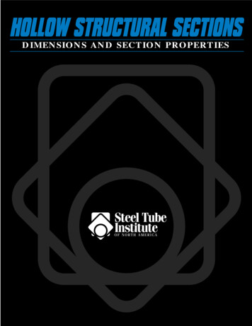
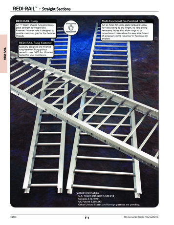
HSS Manufacturing MethodsThe transformation of steel strip into hollow structural sections (HSS) is the result of operations including forming, welding and sizing. Currentlythree methods are being used in North America for the manufacture of HSS. These methods, including two ERW methods and an SAW method, aredescribed below. Both ERW methods meet ASTM A 500 and CSA G-40.21 requirements for the manufacture of HSS, and the ERW sizes included inthis publication may be produced to either standard. The SAW method is not included as a manufacturing process in the ASTM or CSA specification.SAW sizes listed in this publication can be specified to meet desired physical and dimensional criteria of ASTM A500 and CSA G-40.215 6 7Electric Resistance Welding (ERW) ProcessIn the tube mill, flat steel strip (1) is formed continuously around itslongitudinal axis to produce a round tube. This is done by moving thestrip through a progressive set of rolls (2-6). The strip edges (7) areheated by either high frequency induction or contact welding and thenforged together by weld rolls to create a continuous longitudinal weldwithout the addition of filler metal. The weld seam (8) is then cooledand processed through a set of sizing/shaping rolls which cold-form itinto a round (9), square (10) or rectangular (11) section.432189Form-Square Weld-Square (ERW) ProcessIn the weld mill, driven forming dies progressively shape the flat strip(1) by forming the top two corners (2) of the square or rectangular tubein the initial forming station. Subsequent stations form the bottom twocorners (3) of the shape. No cold working of the sides of the shape isperformed, and the shape’s seam is welded by high-frequency contactswhen the tube is near its final shape and size. The welded tube (4) iscooled and then driven through a series of sizing stations which qualifiesthe tube’s final dimensions.1041233Submerged Arc Weld (SAW) ProcessTwo identical pieces of flat strip (1) are placed in a press brake andformed into two identical halves (2) of a finished tube size. A backup baris tack welded to each leg of one of the half-sections (3). The two halfsections are fitted together toe-to-toe (4) and welded by the submergedarc process to complete the square or rectangular section (5).251211234211
STI/HSS Member CompaniesAtlas Tube, Inc.200 Clark Street, P.O. Box 970Harrow, Ontario N0R 1G0Telephone: (519) 738-3541(800) 265-6912Fax: (519) 738-3537IPSCO Tubulars Inc.P.O. Box 18, 2011 7th AvenueCamanche, IA 52730Telephone: (563) 242-0000(800) 950-4772Fax: (563) 242-9137Bull Moose Tube Company1819 Clarkson Road, Suite 100Chesterfield, MO 63017Telephone: (636) 537-2600(800) 325-4467Fax: (636) 537-5848LTV Copperweld1855 East 122nd StreetChicago, IL 60633Telephone: (800) 733-5683Fax: (773) 646-6128(In Canada)14 Holtby AvenueBrampton, OntarioCanada L6X 2M3Telephone: (905) 451-2400(800) 268-3005Fax: (905) 840-4716Eugene Welding CompanyP.O. Box 249Marysville, MI 48040Telephone: (810) 364-7421(800) 336-3926Fax: (810) 364-4347Hanna Steel CorporationP.O. Box 558, Fairfield, AL 35064Telephone: (205) 780-1111(800) 633-8252Fax: (205) 783-8296Hannibal Industries, Inc.P.O. Box 58814, 3851 Santa Fe Ave.Los Angeles, CA 90058Telephone: (323) 588-4261Fax: (323) 589-5640Independence Tube Corporation6226 W. 74th StreetChicago, IL 60638-6196Telephone: (708) 496-0380(800) 376-6000Fax: (708) 563-1950Maverick Tube Corporation16401 Swingley Ridge Road,Suite 700Chesterfield, MO 63017Telephone: (314) 733-1600(800) 840-8823Fax: (314) 733-1677Novamerican Steel Inc.2175 Hymus BoulevardDorval, Quebec, Canada H9P 1J8Telephone: (514) 335-6682(800) 361-1496Fax: (514) 683-5285(In United States)600 Dean Sievres PlaceMorrisville, PA 19067Telephone: (215) 295-8813Fax: (215) 295-8798OF NORTH AMERICA3Productos Laminadosde Monterrey, SA de CVHeadquarters & Monterrey PlantAve. Lazaro Cardenas 1525 Pte.Col. Nino ArtilleroMonterrey, N.L. Mexico C.P. 64280Telephone: (8) 351-1625(8) 351-1070Fax: (8) 351-0322(U.S. Office)Prolamsa, Inc.12603 SW Freeway, Suite 521Stafford, TX 77477Telephone: (281) 494-0900Fax: (281) 494-0990Valmont Industries(Structural Tube Division)P.O. Box 2620Tulsa, OK 74101Telephone: (918) 583-5881(800) 331-3002Fax: (918) 585-1927Vest, Incorporated6023 Alcoa AvenueLos Angeles, CA 90058Telephone: (323) 581-8823(800) 421-6370Fax: (323) 581-3465Welded Tube of Canada Limited111 Rayette RoadConcord, Ontario,Canada L4K 2E9Telephone: (905) 669-1111(800) 565-8823Fax: (905) 738-4070
ForewordTables of allowable axial compressive loads, in kips, are presented for square, rectangular and round hollow structural sections (HSS) manufactured by the electric resistance welding (ERW) method and for square and rectangular HSS manufactured by the submerged arc welding (SAW)method. Tables of allowable stresses for compression members of 42 ksi to 70 ksi specified minimum yield stress are also included.The allowable axial compressive loads, in kips, and the allowable axial compressive stresses, in ksi, have been calculated in accordance with the1989 “Specification for Structural Steel Buildings - Allowable Stress Design and Plastic Design” published by the American Institute of SteelConstruction. The allowable loads are based upon section property data for HSS that were recalculated in 1996 to account for today’s more precisemanufacturing methods. Recalculated section property data for HSS is published in “Hollow Structural Sections - Dimensions and Section Properties”available from the Steel Tube Institute of North America.Tables for square and rectangular HSS are presented for Fy 46 ksi and for Fy 50 ksi. Separate tables are used for HSS sizes produced by theERW and SAW manufacturing methods.Tables for round HSS are presented for Fy 42 ksi, Fy 46 ksi, and Fy 50 ksi. Only round sizes produced by the ERW manufacturing methodare included.The allowable axial loads have been calculated for effective lengths, KL, with respect to the least radius of gyration (r or ry) varying from 0 to 40feet. AlSC “Specification” Appendix B5.2 is used to calculate the allowable loads for members with slender elements. These members are identified inthe tables with an asterisk (*) immediately following the design wall thickness parameter.The properties at the bottom of the tables are useful for determining column strength with respect to the major axis and for the design of columnssubject to combined axial and bending loads.Refer to part 3, Column Design, in the AISC 9th Edition “Manual of Steel Construction” for a discussion of effective length, strength about themajor axis, and combined axial and bending loading (interaction). Symbols in these tables follow those used in the AISC “Manual”.The tabulated values of allowable axial compressive stresses on pages 124 through 126, are calculated in accordance withthe requirements of AISC “Specification” Chapter E, Formulae (E2-1) and (E2-2).The information presented in this publication has been prepared in accordance with recognized engineering principles and is for general information only.While it isbelieved to be accurate, this information should not be used or relied upon for any specific application without competent professional examination and verification of itsaccuracy, suitability, and applicability by a licensed professional engineer, designer, or architect.The publication of the material contained herein is not intended as arepresentation or warranty on the part of The Steel Tube Institute of North America or of any other person named herein, that this information is suitable for any generalor particular use or of freedom from infringement of any patent or patents. Anyone making use of this information assumes all liability arising from such use.Caution must be exercised when relying upon other specifications and codes developed by other bodies and incorporated by reference herein since such material may bemodified or amended from time to time subsequent to the printing of this edition.The Institute bears no responsibility for such material other than to refer to it andincorporate it by reference at the time of the initial publication of this edition.Table of ContentsPagePageHow to Use the Column Load Tables 5Round HSS (ERW) Fy 42 ksi 78Round HSS (ERW) Fy 46 ksi 93Round HSS (ERW) Fy 50 ksi 108Column Load Tables:Square HSS (ERW)Rectangular HSS (ERW)Fy 46 ksi 6Fy 46 ksi 14Square HSS (ERW)Rectangular HSS (ERW)Fy 50 ksi 36Fy 50 ksi 44Square HSS (SAW)Rectangular HSS (SAW)Fy 46 ksi 67Fy 46 ksi 69Square HSS (SAW)Rectangular HSS (SAW)Fy 50 ksi 72Fy 50 ksi 74Allowable Stress TablesFy 42 ksi 124Fy 46 ksi 124Fy 50 ksi 125Fy 60 ksi 125Fy 65 ksi 126Fy 70 ksi 126“Designs forthe 21st Century”4
How To Use The Column Load TablesExample IExample IIISelect the lightest 8-inch square ERW HSS column of Fy 46 ksi(ASTM A500 Gr. B) to support a concentrated axial compressiveload of 152 kips. The largest effective length, KL, is 20 feet.Select the lightest 10-inch x 6-inch rectangular ERW HSS columnof Fy 50 ksi (ASTM A500 Gr. C) to support a concentrated axialcompressive load of 220 kips. The effective length, KL, with respectto the minor axis is 16 feet. The effective length, KL, with respect tothe major axis is 30 feet.Enter the Fy 46 ksi table (page 8) for the 8-inch square ERW HSS.Read across the row at KL 20 and note the following:8 x 8 x 5/8x 1/2x 3/8x 5/16x 1/4can carry 296 kipscan carry 247 kipscan carry 193 kipscan carry 163 kipscan carry 133 kipsEnter the Fy 50 ksi table (page 51) for the 10-inch x 6-inchrectangular ERW HSS. Read across the row at KL 16 and note thefollowing: 152 kips - O.K. 152 kips - O K. 152 kips - O.K 152 kips - O.K. 152 kips - No Good10 x 6 x 5/8x 1/2x 3/8can carry 305 kipscan carry 256 kipscan carry 200 kips 220 kips - O.K. 220 kips - O.K. 220 kips - No GoodSelect: 8 x 8 x 5/16 HSS (Weight 31.84 lbs./ft.)Tentatively select: 10 x 6 x 1/2rx / ry 1.49Example IIEquivalent effective length for the major axis:30 / 1.49 20.1 ft. 16 ft. Therefore major axis governs.Select the lightest square ERW HSS column of Fy 46 ksi(ASTM A500 Gr. B) to support a concentrated axial compressiveload of 120 kips. The largest effective length, KL, is 14 feet.Enter the same table, read across the row at KL 20.1 and notethe following:Enter the Fy 46 ksi tables for square HSS. Read across therows at KL 14 and note the following:10 x 6 x 5/8 can carry 229 kips (interpolated) 220 kipsrx / ry 1.50 - O.K.5 x 5 x 1/2 can carry 125 kips 120 kips - O.K.(Weight 28.43 lbs./ft.) (page 10)10 x 6 x 1/2 can carry 195 kips (interpolated) 220 kips - No GoodFinal Selection: 10 x 6 x 5/8 HSS (Weight 59.32 lbs./ft.)5 1/2 x 5 l/2 x 3/8 can carry 124 kips 120 kips - O.K.(Weight 24.93 lbs. /ft.) (page 9)6 x 6 x 5/16 can carry 124 kips l20 kips - O.K.(Weight 23.34 lbs./ft.) (page 9)7 x 7 x l/4 can carry 130 kips 120 kips - O.K.(Weight 22.42 lbs./ft.) (page 8)8 x 8 x 1/4 can carry 158 kips 120 kips - O.K.(Weight 25.82 lbs./ft.) (page 8)9 x 9 x 3/16 can carry 129 kips 120 kips - O.K.(Weight 22.18 lbs./ft.) (page 7)Final Selection: 9 x 9 x 3/16 HSS (Weight 22. l8 lbs./ft.)5
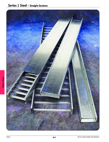
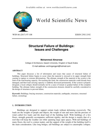
HSS / SquareStructural Steel TubingFy 46Allowable Concentric Loads in KipsNominal Size16 x 16Wall Thickness5/8Weight Per Foot127.37Effective length KL in feetDesign Wall Thickness1/2103.30ERW14 x 591090489789188416171819205/8110.3612 x 121/23/889.6868.315/1657.360.349Fy 46 502345966958954949944678910PROPERTIESArea, In.2I, 248r, 64.79B, Bending 10.2740.2690.2640.261a 10620516913011013411186.273.281.868.2*Slender element section. Width-Thickness and Depth-Thickness ratio exceeds AISC "Specification" Section B5.1 limiting value of 253 / Fy.653.345.437.0
HSS / SquareStructural Steel TubingFy 46Allowable Concen
Refer to part 3, Column Design, in the AISC 9th Edition “Manual of Steel Construction . modified or amended from time to time subsequent to the printing of this edition.The Institute bears no responsibility for such material other than to refer to it and incorporate it by reference at the time of the initial publication of this edition. 5 Example I Select the lightest 8-inch square ERW .