Transcription
C H A P T E R5Services ImplementationPlease refer to the Service Tiers section for the different services offered to different types of tenants,Gold, Silver, Bronze, and Copper. This section discusses the implementation on the services nodes, theApplication Control Engine (ACE) 4710 for Server Load Balancing (SLB), the Adaptive SecurityAppliance (ASA) 5585-based perimeter firewall, the ASA 5555-x-based VPN access, and the VirtualSecurity Gateway (VSG) for the virtualized compute firewall. ACE 4710 Appliance, page 5-1 ASA Perimeter Firewall, page 5-11 ASA VPN Configuration, page 5-23 Compute Firewall, page 5-26 Services Best Practices and Caveats, page 5-46ACE 4710 ApplianceThis section presents the following topics: ACE Redundancy Configuration, page 5-1 ACE Context Distribution, page 5-3 ACE SLB Configuration, page 5-3ACE Redundancy ConfigurationThe ACE appliances used in this solution are configured in active/active redundancy mode, i.e., a pairof ACE appliances forming a Fault-Tolerant (FT) peer will forward traffic for different contexts. Toprovide redundancy, a FT VLAN is configured on both ACE appliances. This FT VLAN is used by theACE appliances to send state information, replication data redundancy protocol packets, heartbeatpackets, and configuration synchronization packets. For the ACE appliances, the FT VLAN should betrunked using the ft-port vlan vlan-id command. This identifies a FT VLAN on a trunk port andensures that proper QoS treatment is applied to packets on that VLAN. Proper QoS treatment ensuresthat FT messages between peers are not dropped in the network. The Nexus 7000 devices are alsoconfigured to ensure that proper QoS treatment is given to FT packets.Cisco Virtualized Multiservice Data Center (VMDC) 2.3Implementation Guide5-1
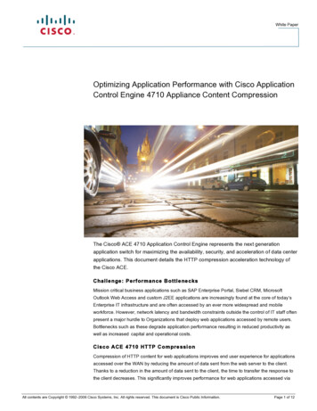
Chapter 5Services ImplementationACE 4710 ApplianceIn this solution, the ACE appliance FT packets are switched through the Layer 2 (L2) network. The ACEFT peer connects to the L2 network through port-channels with all four Gigabit Ethernet interfaces asmembers. The endpoints of these port-channels are vPCs on a pair of Nexus 7000 switches. Based on L2forwarding rules on the Nexus 7000 switches, redundancy packets of the ACE received by a Nexus 7000switch will be switched to the vPC that connects to the other ACEFT peer. It will be rare for the redundancy packets to transverse any other link, especially the Nexus 7000vPC peer links. Figure 5-1 shows the L2 connection between the ACE appliances and the Nexus 7000switches. A single management VLAN is used to manage the four ACE appliances used in this solution.To avoid MAC collision, each of the ACE appliances are assigned a different shared-vlan hostid toensure that they derive their MAC addresses from a different MAC address pool. The ACE modules andappliances are built with 16 pools of MAC addresses.Figure 5-1ACE-Nexus 7000 TopologyBelow is a sample configuration required for ACE redundancy.shared-vlan-hostid 3peer shared-vlan-hostid 4context customer silver1allocate-interface vlan 60allocate-interface vlan 501allocate-interface vlan 601allocate-interface vlan 701member silver-sticky-classft peer 1heartbeat interval 1000heartbeat count 10ft-interface vlan 1998ft group 31peer 1priority 255peer priority 120associate-context customer silver1inserviceinterface port-channel 1ft-port vlan 1998Cisco Virtualized Multiservice Data Center (VMDC) 2.35-2Implementation Guide
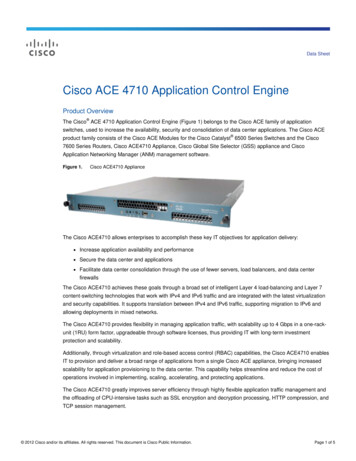
Chapter 5Services ImplementationACE 4710 Applianceswitchport trunk allowed -720,1601-1610port-channel load-balance src-dst-portACE Context DistributionA total of 40 contexts are used in this validation. In this solution, each Gold tenant network configurationis validated with two ACE contexts. One ACE context is used to load balance tenant Private, or PVT,server resources, and the other ACE context is used to load balance Demilitarized Zone (DMZ) serverresources. A single ACE context is assigned to each Silver tenant. Two ACE 4710 appliance are usedfor Gold tenants, while two other ACE 4710s are used for Silver tenants. The ACEAP-04-LIC licensesare installed in each appliance. This license type allows the system to reach the context and throughputlimits of each appliance. The number of ACE appliances can be increased to accommodate moreGold/Silver tenants.Figure 5-2 shows the ACE context distribution used in this solution. For effective load balancing andredundancy, half of each tenant type is active in each of the ACE 4710s assigned to that tenant type,while the other half will be standby on the other ACE 4710 appliance.Figure 5-2ACE Context DistributionACE SLB ConfigurationThe ACE contexts for the tenants are configured in a one-arm mode. Using this mode, the ACE datainterfaces are in the same VLAN with that of the servers. In this implementation, the ACE VIP addressesare also chosen to be in the same server subnet. This eliminates the need to have additional static routeson the Nexus 7000 aggregation switches. Each ACE context is configured with a default route pointingCisco Virtualized Multiservice Data Center (VMDC) 2.3Implementation Guide5-3
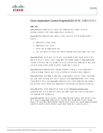
Chapter 5Services ImplementationACE 4710 Applianceto the VLAN interface of the Nexus 7000. Client addresses are translated to addresses in the same serversubnet to ensure load-balanced return traffic goes to the ACE context. Each ACE context is configuredto load balance Layer 4 (L4) - Layer 7 (L7) traffic. L4 load-balancing policies are configured for UserDatagram Protocol (UDP) traffic, while L7 load-balancing policies are configured for HypertextTransfer Protocol (HTTP) traffic.In this implementation, each Gold and Silver ACE private context is configured to load balance webclient traffic, web tier traffic directed to the app tier VIP, and app tier traffic directed to the Database(DB) tier VIP address. An ACE DMZ context is configured for each Gold tenant to load balance trafficdestined to the DMZ servers.Figure 5-3 shows the ACE SLB topology for Gold and Silver tenants.Figure 5-3Figure 5-3.Gold and Silver ACE ContextThe following sections show the ACE SLB configurations.Cisco Virtualized Multiservice Data Center (VMDC) 2.35-4Implementation Guide
Chapter 5Services ImplementationACE 4710 ApplianceRserver ConfigurationThe rserver configuration is used to associate the real server IP address to an object name. This objectname is the rserver name and will be used to define members of a server farm. A sample configurationis shown below.Sample Rserver Configurationrserver hostip addressinservicerserver hostip addressinservicerserver hostip 1.1.12web-server311.1.1.13Server Farm ConfigurationThe server farm is a set of real servers providing the same application service. Client traffic is loadbalanced among the real servers in a server farm using a predictor algorithm. By default, the predictorused is round robin and this is used in this solution. The server farm configuration also provide aconvenient way to take real servers offline or bring real servers online. Real servers information is addedinto the server farm configuration using their associated rserver names. In addition, probes can beapplied to a server farm to ensure that the VIP addresses are taken offline if there is no real serveravailable to handle requests. A sample configuration is shown below.serverfarm host app-serverfarmrserver app-server1inservicerserver app-server2inservicerserver app-server3inserviceserverfarm host db-serverfarmrserver db-server1inservicerserver db-server2inservicerserver db-server3inserviceserverfarm host udp-serverfarmrserver udp-hostinserviceserverfarm host udp-serverfarm:30000rserver udp-host:30000inserviceserverfarm host web-serverfarmrserver web-server1rserver web-server2rserver web-server3rserver web-spirentinserviceCisco Virtualized Multiservice Data Center (VMDC) 2.3Implementation Guide5-5
Chapter 5Services ImplementationACE 4710 ApplianceClass-MapsManagement, L4, and L7 class-maps are used in the configuration. The Management class-map definesmanagement related traffic that is allowed to the ACE contexts. L4 class-maps are used to define the L4ports that are used as match criteria for client traffic that will be load balanced. Typically, UDP andTransmission Control Protocol (TCP) ports are used as match criteria. L7 class-maps are used to definethe L7 header values that will be used as match criteria for load balancing. In this implementation, HTTPURL values are used to define criteria. A sample configuration used in this solution is shown below.Sample Management Class-mapclass-map2 match3 match4 match5 match6 match7 matchtype management match-any management-trafficprotocol ssh anyprotocol http anyprotocol https anyprotocol icmp anyprotocol telnet anyprotocol snmp source-address 192.168.0.0 255.255.0.0Sample L4 Class-mapclass-map2 matchclass-map2 matchclass-map2 matchclass-map2 matchclass-map2 matchmatch-all udp-vipvirtual-address 11.1.1.111match-all udp-vip:30000virtual-address 11.1.1.111match-all web- app-vipvirtual-address 11.1.2.111match-all web-vipvirtual-address 11.1.1.111match-all app- db-vipvirtual-address 11.1.3.111udp eq 69udp eq 30000tcp eq wwwtcp eq wwwtcp eq wwwSample L7 Class-mapclass-map2 matchclass-map2 match3 matchclass-map2 matchclass-map2 match3 matchclass-map2 match3 matchtype http loadbalance match-any cm-app-subnetsource-address 11.1.2.0 255.255.255.0type http loadbalance match-any cm-httphttp url /.*.txthttp url /.*.htmltype http loadbalance match-any cm-web-subnetsource-address 11.1.1.0 255.255.255.0type http loadbalance match-all cm-app- dbclass-map cm-httpclass-map cm-app-subnettype http loadbalance match-all cm-web- appclass-map cm-httpclass-map cm-web-subnetNAT ConfigurationEither Source NAT with PAT (SNAT) or Policy Based Routing (PBR) are used to implement the one-armACE topology. In this solution, we use SNAT with PAT to implement the one-arm ACE configuration.This involves the ACE translating the client source address to an address in a pool to ensure that clientreturn traffic from the server farm is received by the ACE appliance. We use a server farm subnet addressrange to define the NAT pool, and this eliminates the need to have static routes on the Nexus 7000switches. The server receiving the client traffic will have an ARP entry that it receives from the ACEcontext. We use PAT to ensure that we do not quickly deplete the pool when client requests are received.The NAT pool is defined on the interface, and this NAT pool is associated with an L4 policy-map. Asample configuration used in this solution is shown below.Cisco Virtualized Multiservice Data Center (VMDC) 2.35-6Implementation Guide
Chapter 5Services ImplementationACE 4710 ApplianceSample NAT configurationinterface vlan 201description web tierip address 11.1.1.22 255.255.255.0alias 11.1.1.21 255.255.255.0peer ip address 11.1.1.23 255.255.255.0access-group input web-aclnat-pool 1 11.1.1.24 11.1.1.30 netmask 255.255.255.0 patnat-pool 11 11.1.1.41 11.1.1.41 netmask 255.255.255.255nat-pool 12 11.1.1.42 11.1.1.42 netmask 255.255.255.255service-policy input lb-policyno shutdowninterface vlan 301description app tierip address 11.1.2.22 255.255.255.0alias 11.1.2.21 255.255.255.0peer ip address 11.1.2.23 255.255.255.0access-group input app-aclnat-pool 2 11.1.2.24 11.1.2.30 netmask 255.255.255.0 patservice-policy input web- app-lbno shutdowninterface vlan 401description db tierip address 11.1.3.22 255.255.255.0alias 11.1.3.21 255.255.255.0peer ip address 11.1.3.23 255.255.255.0access-group input db-aclnat-pool 3 11.1.3.24 11.1.3.30 netmask 255.255.255.0 patservice-policy input app- db-lbno shutdownPolicy-MapsManagement, L4, and L7 policy-maps are used in the configuration. The Management policy-mapdefines the action that will be taken if there is a match in the management class-map. The L4load-balance policy combines the L4 class-map with an L7 load-balance policy. This L4 load-balancepolicy defines what traffic should be load balanced and what load-balance policy should be applied tothis traffic. The load-balance policy applied to matched traffic is defined by the L7 load-balance policy.This policy defines L7 match criteria for received traffic and the server farm that handles L7 traffic. L4polices are applied to data interfaces on the ACE context using the service-policy. The sampleconfigurations used in this solution are shown below.Sample Management Configurationpolicy-map type management first-match management-trafficclass management-trafficpermitSample L7 Policy-mappolicy-map type loadbalance first-match app- db-lb-policyclass cm-app- dbsticky-serverfarm customer gold1-app- dbpolicy-map type loadbalance first-match udp-lb-policyclass class-defaultserverfarm udp-serverfarmpolicy-map type loadbalance first-match udp-lb-policy:30000class class-defaultserverfarm udp-serverfarm:30000policy-map type loadbalance first-match web- app-lb-policyclass cm-web- appCisco Virtualized Multiservice Data Center (VMDC) 2.3Implementation Guide5-7
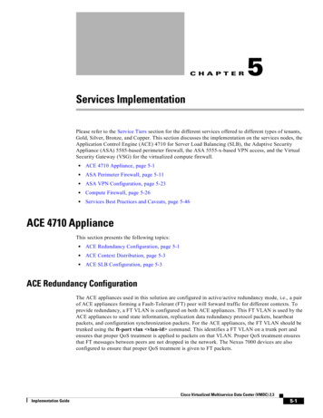
Chapter 5Services ImplementationACE 4710 Appliancesticky-serverfarm customer gold1-web- apppolicy-map type loadbalance first-match web-lb-policyclass cm-httpsticky-serverfarm customer gold1-httpSample L4 Policy-mappolicy-map multi-match app- db-lbclass app- db-viploadbalance vip inserviceloadbalance policy app- db-lb-policyloadbalance vip icmp-reply activenat dynamic 3 vlan 401policy-map multi-match lb-policyclass web-viploadbalance vip inserviceloadbalance policy web-lb-policyloadbalance vip icmp-reply activenat dynamic 1 vlan 201connection advanced-options tcp pmclass udp-viploadbalance vip inserviceloadbalance policy udp-lb-policyloadbalance vip icmp-replynat dynamic 11 vlan 201connection advanced-options udp pmclass udp-vip:30000loadbalance vip inserviceloadbalance policy udp-lb-policy:30000loadbalance vip icmp-reply activenat dynamic 12 vlan 201connection advanced-options udp pmpolicy-map multi-match web- app-lbclass web- app-viploadbalance vip inserviceloadbalance policy web- app-lb-policyloadbalance vip icmp-reply activenat dynamic 2 vlan 301ACE SLB Traffic Path OverviewFigure 5-3 shows the ACE SLB traffic path overview.Cisco Virtualized Multiservice Data Center (VMDC) 2.35-8Implementation Guide
Chapter 5Services ImplementationACE 4710 ApplianceFigure 5-4ACE SLB Traffic Path OverviewAnyWeb VIP Traffic Path1.Traffic destined to the web VIP is received from Gold and Silver tenant client networks.2.Traffic destined to the web VIP will be forwarded by the Nexus 7000 aggregation routers (on thesame web VLAN) to the ACE context.3.At the ACE context, client traffic is load balanced to the server in the server farm that will handlethe client request.4.The return traffic from the web server will be forwarded to the ACE context.5.The ACE context will forward the client to its gateway, which is an HSRP VIP address on the Nexus7000 aggregation router.Web—APP VIP Traffic Path1.Traffic destined to the app VIP from a web server, will be forwarded to the web server gatewaywhich is the nexus 7000 aggregation router2.the nexus 7000 aggregation router will forward this traffic to the ACE context. Both nexus 7000aggregation router and the ACE Context app interface are in the same VLAN3.At the ACE context, web server traffic is load balanced to a server in the app server farm.4.The return traffic from the app server will be sent to the ACE context. This is due to the web serveraddress being translated to a pool on the ACE on the same server subnet as the app servers.Cisco Virtualized Multiservice Data Center (VMDC) 2.3Implementation Guide5-9
Chapter 5Services ImplementationACE 4710 Appliance5.The ACE context will send it to the web server that originated the traffic. Return traffic does notreach the nexus 7000 aggregation router.APP—DB VIP Traffic Path1.Traffic destined to the DB VIP address from an app server will be forwarded to the app servergateway, which is the Nexus 7000 aggregation router.2.The Nexus 7000 aggregation router will forward this traffic to the ACE context. Both the Nexus7000 aggregation router and the ACE context DB interface are in the same VLAN.3.At the ACE context, app server traffic is load balanced to a server in the DB server farm.4.The return traffic from the DB server will be sent to the ACE context. This is due to the app serveraddress being translated to a pool on the ACE on the same server subnet as the DB servers.5.The ACE context will send this traffic to the app server that originated the traffic. Return traffic doesnot reach the Nexus 7000 aggregation router.Table 5-1 and Table 5-2 provide an overview of Gold and Silver client traffic that will be load balanced.Note that L7 class-maps are used to match allowed HTTP URL and client source address.Table 5-1Allowed SLB Traffic for Gold TenantTrafficOrigination DestinationOperationRestriction ModeAnyWeb VIPLoad balance to web server farmL7 class-map based on HTTP URLAnyDMZ VIPLoad balance to DMZ server farm L7 class-map based on HTTP URL(DMZ context)AnyApp VIPReset/Drop ConnectionL7 class-map based on HTTP URLand Source IPAnyDB VIPReset/Drop ConnectionL7 class-map based on HTTP URLand Source IPWeb tierApp VIPLoad balance to app server farmL7 class-map based on HTTP URLand Source IPWeb tierDB VIPResetL7 class-map based on HTTP URLand Source IPApp tierDB VIPLoad balance to DB server farmL7 class-map based on HTTP URLand Source IPApp tierWeb VIPLoad balance to web server farmL7 class-map based on HTTP URLDB tierWeb VIPLoad balance to web server farmL7 class-map based on HTTP URLTable 5-2Allowed SLB Traffic for Silver TenantTrafficOrigination DestinationOperationRestriction ModeAnyWeb VIPLoad balance to web server farmL7 class-map based on HTTP URLAnyApp VIPReset/Drop ConnectionL7 class-map based on HTTP URL andSource IPAnyDB VIPReset/Drop ConnectionL7 class-map based on HTTP URL andSource IPCisco Virtualized Multiservice Data Center (VMDC) 2.35-10Implementation Guide
Chapter 5Services ImplementationASA Perimeter FirewallTable 5-2Allowed SLB Traffic for Silver Tenant (continued)Web tierApp VIPLoad balance to app server farmL7 class-map based on HTTP URL andSource IPWeb tierDB VIPResetL7 class-map based on HTTP URL andSource IPApp tierDB VIPLoad balance to DB server farmL7 class-map based on HTTP URL andSource IPApp tierWeb VIPLoad balance to web server farmL7 class-map based on HTTP URLDB tierWeb VIPLoad balance to web server farmL7 class-map based on HTTP URLRefer to Associating a Layer 7 SLB Policy Map with a Layer 3 and Layer 4 SLB Policy Map foradditional information on ACE SLB configuration.ASA Perimeter FirewallThis section presents the following topics: ASA Firewall Redundancy, page 5-11 Gold Tenant ASA Firewall Configuration, page 5-13 Copper Firewall Details, page 5-16ASA Firewall RedundancyIn this implementation, two ASA firewalls are used to provide Gold tenants with security services, e.g.,inspection, ACL, NAT, etc., and these firewalls are configured in active/active redundancy mode tomaximize their capability. Separate, dedicated interfaces are used for failover and stateful failoverinterfaces between the ASA firewall. For more information on how to set up ASA firewall redundancy,refer to the following links: Configuring Active/Active Redundancy VMDC 2.2 Implementation GuideASA port-channels are used to connect to the Nexus 7000 aggregation switch vPC. The data VLANsused for communication through the ASA are trunked on these interfaces. To protect against single vPCfailures, interfaces allocated to firewall tenants should be monitored. This ensures that if a failure occurs,the failure policy condition also occurs. For effective load balancing and redundancy, the tenants'contexts are distributed among the two ASA firewalls used in this solution (Table 5-2).Cisco Virtualized Multiservice Data Center (VMDC) 2.3Implementation Guide5-11
Chapter 5Services ImplementationASA Perimeter FirewallFigure 5-5ASA Firewall SetupBelow is the ASA sample firewall failover configuration.failoverfailover lan unit primaryfailover lan interface FL Port-channel48.4093failover polltime unit 5 holdtime 15failover replication httpfailover link SL Port-channel48.4094failover interface ip FL 9.9.9.1 255.255.255.0 standby 9.9.9.2failover interface ip SL 9.9.10.1 255.255.255.0 standby 9.9.10.2failover group 1preemptreplication httppolltime interface 1 holdtime 5interface-policy 50%failover group 2secondarypreemptreplication httppolltime interface 1 holdtime 5interface-policy 50%ASA Failover Configuration Required on --dc02-asa-fw1/customer-gold1# sh run monitor-interfacemonitor-interface insidemonitor-interface outsidemonitor-interface dmzTwo failover groups on the ASA are used to distribute active contexts among the primary ASA and thesecondary ASA. By default, failover group 1 is assigned to the primary ASA. To have active contextson the secondary ASA, failover group 2 is assigned to the secondary ASA. To distribute contexts on bothASA devices, half of all configured Gold contexts are assigned to failover group 1, and the other halfare assigned to failover group 2. A sample configuration for two Gold tenants is shown below.ASA Context Configurationdc02-asa-fw1# sh run context customer-gold1context customer-gold1allocate-interface Management0/0allocate-interface Port-channel1.1201allocate-interface Port-channel1.1301Cisco Virtualized Multiservice Data Center (VMDC) 2.35-12Implementation Guide
Chapter 5Services ImplementationASA Perimeter Firewallallocate-interface Port-channel1.1401config-url disk0:/vmdc3.1/customer-gold1join-failover-group 1!dc02-asa-fw1# sh run context customer-gold6context customer-gold6allocate-interface Management0/0allocate-interface Port-channel1.1206allocate-interface Port-channel1.1306allocate-interface Port-channel1.1406config-url disk0:/vmdc3.1/customer-gold6join-failover-group 2!Gold Tenant ASA Firewall ConfigurationFigure 5-6 provides an overview of a typical ASA firewall configuration for a Gold tenant in thisimplementation.Figure 5-6Gold Tenant ASA Firewall Configuration OverviewCisco Virtualized Multiservice Data Center (VMDC) 2.3Implementation Guide5-13
Chapter 5Services ImplementationASA Perimeter FirewallRouting ConfigurationRefer to ASA Firewall Context Routing Configuration for the configuration required to route throughthe ASA. To route between the Private and DMZ contexts for a tenant, the mac-address auto prefix 16-bit prefix command is configured to ensure that all active interfaces on the ASA have a uniqueMAC address. This configuration is required for inter-context routing on the ASA.ACL ConfigurationACLs are configured on the Gold tenant ASA firewall context outside interfaces to allow permittedprotocol traffic from Service Provider client networks to be forwarded to the inside and DMZ networks.In this implementation, an object group is used to simplify the ACL configuration. Two object-grouptypes are used in the ACL configuration. The network-object group is used to identify the networks tobe allowed, while the service-object group is used to identify the UDP and TCP ports that are allowedfor these networks. Also, ACLs are applied on the context DMZ interfaces to identify the DMZ servertraffic that should be allowed to the private server networks. ACLs are also configured in the DMZfirewall contexts for the tenants. These ACLs control allowed traffic from Internet to DMZ networks.A sample configuration of a configured object group and ACL is shown below.dc02-asa-fw1/customer-gold1# sh run object-groupobject-group network SP-CLIENTS-NETWORKnetwork-object 40.1.0.0 255.255.0.0network-object 10.1.0.0 255.255.0.0network-object 131.0.0.0 255.0.0.0object-group service SP-CLIENTS-PROTOCOLS-TCP tcpport-object eq wwwport-object eq httpsport-object eq ftpport-object eq sshport-object eq domainobject-group service SP-CLIENTS-PROTOCOLS-UDP udpport-object eq tftpport-object eq domainport-object range 10000 30000object-group network DMZ-VPN-NETWORKnetwork-object 11.1.4.0 255.255.255.0network-object 11.255.0.0 255.255.0.0object-group service DMZ-VPN-PROTOCOLS-TCP tcpport-object eq wwwport-object eq httpsport-object eq sshport-object eq ftpobject-group service DMZ-VPN-PROTOCOLS-UDP udpport-object eq tftpport-object eq domainport-object range 10000 30000dc02-asa-fw1/customer-gold1# sh run access-listaccess-list DMZ-VPN extended permit tcp object-group DMZ-VPN-NETWORK any object-groupDMZ-VPN-PROTOCOLS-TCPaccess-list DMZ-VPN extended permit udp object-group DMZ-VPN-NETWORK any object-groupDMZ-VPN-PROTOCOLS-UDPaccess-list DMZ-VPN extended permit icmp object-group DMZ-VPN-NETWORK anyaccess-list OUTSIDE extended permit tcp object-group SP-CLIENTS-NETWORK anyobject-group SP-CLIENTS-PROTOCOLS-TCPaccess-list OUTSIDE extended permit udp object-group SP-CLIENTS-NETWORK anyobject-group SP-CLIENTS-PROTOCOLS-UDPaccess-list OUTSIDE extended permit icmp object-group SP-CLIENTS-NETWORK anydc02-asa-fw1/customer-gold1# sh run access-groupaccess-group OUTSIDE in interface outsideaccess-group DMZ-VPN in interface dmzdc02-asa-fw1/customer-gold1#Cisco Virtualized Multiservice Data Center (VMDC) 2.35-14Implementation Guide
Chapter 5Services ImplementationASA Perimeter FirewallNAT ConfigurationDue to the use of static default routes on tenant contexts, dynamic NAT is configured on the privatetenant contexts. To enable the DMZ context, know how to forward return traffic for Service Providerclients from the DMZ networks. This dynamic NAT translates the source IP addresses of ServiceProvider clients whose traffic is destined to DMZ server network. Static NAT configuration is also addedin the DMZ context to translate IP addresses of DMZ resources to global addresses. Traffic sent to theseresources from the Internet must be destined to their global IP addresses. Network objects are used toidentify addresses to be translated and the pool or public IP to use during translation. A sample NATconfiguration is shown below.Dynamic NAT fw1/customer-gold1# sh run objectobject network SP-CLIENTS-POOLrange 51.1.1.1 51.1.1.254object network SP-CLIENTS- DMZrange 0.0.0.0 255.255.255.255dc02-asa-fw1/customer-gold1# sh run nat!Static NAT configurationdc02-asa-fw1/customer-gold1# changeto c customer-gold1-dmzdc02-asa-fw1/customer-gold1-dmz# sh run objectobject network SERVER1host 11.1.4.11object network SERVER3host 11.1.4.13object network SERVER2host 11.1.4.12object network WEB-VIPhost 11.1.4.111object network t1object network SERVER8host 11.1.4.100object network SERVER7host 11.1.4.151dc02-asa-fw1/customer-gold1-dmz# sh run nat!object network SERVER1nat (dmz,internet) static 100.200.2.24object network SERVER3nat (dmz,internet) static 100.200.2.25object network SERVER2nat (dmz,internet) static 100.200.2.26object network WEB-VIPnat (dmz,internet) static 100.200.2.1object network SERVER8nat (dmz,internet) static 100.200.2.31object network SERVER7nat (dmz,internet) static ation InspectionThe ASA context default inspection policy is used in this implementation. By default, this inspectionpolicy is implicitly applied to all active interfaces configured on an ASA context.Cisco Virtualized Multiservice Data Center (VMDC) 2.3Implementation Guide5-15
Chapter 5Services ImplementationASA Perimeter FirewallCopper Firewall DetailsThe Copper service is used for Internet users to access servers in the DC. Those servers can have publicor private IP addresses. For the private IP address servers, NAT is needed for the access to these servers,and the IP addresses can be overlapped for different tenants.This section presents the following topics: Shared Firewall Setup, page 5-16 NAT Setup, page 5-19Shared Firewall SetupThe Copper tenants' traffic comes from the Internet, and all of the Copper tenants share the same ASAcontext. This is a use case for a tenant to have VMs in the Service Provider public cloud offering andthe VMs are accessed over the Internet. The IP addressing on the tenant VMs can be from routable publicIP addressing space or can be private addressing. In the public addressing, these are reachable directlyfrom the Internet, and each tenant would have a subnet for VMs, that is part of the Service Provider'sblock. In the private addressing scenario, the tenant VMs use a private subnet, and NAT is done on theASA to translate to a set of public IP addresses. With a private addressing model, overlapping subnetscan be used by tenant VMs, however, the public addresses on the outside need to be unique, and NATtranslations need to be used to reach the correct inside interface.Additionally, the inside interface on the ASA connecting to the inside per-tenant VRF instance has aprivate subnet, however, these subnets cannot be overlapping as only one context is used on the ASA. Ifoverlapping addresses on connected interfaces are required, then different contexts on the ASA need tobe used.This section presents the following topics: Public Address Tenants, page 5-16 Private Address Tenants, page 5-17Public Address TenantsFor the tenant servers with the public address, NAT is not needed. Static routes are defined in the ASASMB context to select the egress interface and the next hop. In the Nexus 7000, tenant VRF instancesare created to separate the tenants.From the ASA ViewFor the north to south traffic, the next hop is the HSRP addresses of the individual tenant VRF instanceof the Nexus 7000. For the south to north traffic, the next hop is the HSRP address of a global VLAN,and it uses the global routing table of the Nexus 7000.From the Nexus 7000 Global Routing ViewFor the north to south traffic, the next hop is the shared ASA context outside interface. For the south tonorth traffic, the Nexus 7000 will use its routing table to route the traffic to the PE routers.From the Nexus 7000 Per-Te
Cisco Virtualized Multiservice Data Center (VMDC) 2.3 Implementation Guide Chapter 5 Services Implementation ACE 4710 Appliance In this solution, the ACE appliance FT packets are switched through the Layer 2 (L2) network. The ACE FT peer connects to the L2 network through port-channels with all four Gigabit Ethernet interfaces as members.