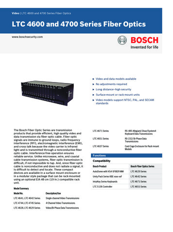
Transcription
Summary of Undersea Fiber Optic NetworkTechnology and SystemsBy Adam MarkowSenior Telecom AnalystThe source of many of the slides is from – The David Ross Group http://www.davidrossgroup.com
A view of the Global SubmarineCable Network (TeleGeography)
Undersea System ElementsRepeatered ExamplesTransoceanic lStationsCoastal NetworkUsing the same elements
Undersea System Elements - Non-Repeatered ExamplesRepeaterless vs. Repeatered: Limited to 400 km span lengthsInter-island NetworkSubmarineCable Sometimes, but not always Less expensive initiallyMore flexible long termLess expensive to operate & maintainMore complex to upgrade Historical advantages of repeaterlessoffset today by current market oversupplyof repeatered production capability and inventoryTerminalStationsCoastal NetworksUsing the same elementsThe choice between repeatered & repeaterlessmust be made on a case by case basisSource – The David Ross Grouphttp://www.davidrossgroup.comTrunk & BranchFestoon
Connecting a Terrestrial Networkwith and Undersea SystemTelehouseBackhaulConnectionCable Station & Beach Manhole.ADMN x STM-1oADMSLTEN x STM-64.ADMPFEOceanCableShoreSection)Ocean groundSLTE – Submarine Line Termination Equipment.PFE – Power Feed Equipment (pushes constantcurrent of 1.5 A across undersea cable link fromCS to CS)
Cable Station Floor PlanGCL Cable Station Requirements:At least 17,000 square feet ( 1900m2 ) of total areaRaised floor, with minimum load tolerance of 500 kg/m2Useable height of at least 2.5mDual cable vaultsDC -48v power, with battery backup for at least 1 hour.Diesel Engine emergency backupHVAC to maintain room temperature between 22 - 24CRing GroundFire/smoke detection, with connection to emergency/control center24 hour access for maintenance and repairBatteryTransmission EquipmentCollocation for backhaulMeeting/training room
Cable Station Transmission ComponentsLINE PAIR #1SLTEUndersea CableCableStationOrderwire & nitoringEquipmentSDHTerminalSDHTerminalOrderwire & MaintenanceLINE PAIR #4OpticalConnectionsofTerrestrial Linkconnectingto Data Center
Land Plant – Line Terminating Equipmentλ1ToSDHEquipmentλλ21- seaCable
Land Plant – Line Terminating EquipmentOTX RXO/E2.5GCONV.ORXO/E2.5GCONV.ORX2.5G ORXOHFECENCODERINSOHFECENCODERINSOH TIMING GENERATOROHFECENCODERINSOH TIMING GENERATOROHFECINSENCODEROH TIMING GENERATOROHE/OCONV.SCRMUXWME10.8G10G SOTXSCR MUXFEC CODORX ShelfSTM-16STM-16STM-16STM-16Timing G CONV.OTXE/O2.5GCONV.OTX2.5G UXTiming GeneratorOHOHFRMSYNC&DSCRTRMFECDECODERDSCR DMUXOHFEC DECSource – NECO/ECONV.DECODERTimingGeneratorSource – The David Ross Grouphttp://www.davidrossgroup.com10G SORXWME10.8G
Land Plant – SDH Ring TerminalSDH MultiplexEquipmentNetworkProtectionEquipmentHigh PerformanceOptical EquipmentWavelengthTerminatingEquipmentLine AmplifierOptical Line ToUndersea CableSource – The David Ross Grouphttp://www.davidrossgroup.comDuplicated Per Fiber Pair
Land Plant – Network Management EquipmentNetwork ManagementSystem WorkstationNetwork ManagementSystem EquipmentInland Network (optional)SDHHPOEVendor EquipmentElement ManagersWTEUndersea Line EquipmentLine MonitoringEquipmentSource – The David Ross Grouphttp://www.davidrossgroup.comTLAPower FeedEquipment
Land Plant – Power Feed EquipmentPR1800 mmCOMPR2PM800 mm800 mmLT800 mmSWTL1TL2800 mm800 mm800 mmCOMFANCURR CONT1,800 )CONV(9 )CONV(5)BLANKLOAD TRFFANSW&RETURNOPE & MONI&C/V SENSORTEST LOADCOMNTEST LOADRECORDER&EARTH TEST*The depth of the frame: 600mmHV PFE ConfigurationSource – KDD SCS
Cable Station and Beach Manhole2025 Taft Street - Hollywood, Florida
Global Crossing Backhaul in Hollywood, FloridaThe optronic connection that starts at Optical Distribution Frame (ODF) in the CableStation and then continues to the ODF at the City Service Point, the Telehouse.Then a separate connection of the circuit is made to the frame of the carrier who willthen take traffic back to the end customer premise.Cable Station
Undersea Cable Landing Configuration Submerged Plant Beach Manhole Shore Section Land Sections Terminal Station Terminal Station EquipmentTerminal StationNetworkManagementLand SectionBeach ManholeBranching UnitCableRepeaterOptical & Power FeedTransmission EquipmentEquipment
Cable ShipYes, the cable really does rest onthe Ocean Floor!RepeaterSubmarine MountainSubmarine Cable
South America Physical Map South America ERZ border at 12 nmi South American Crossing Segmentsare mostly outside of the ERZERZ Economic Resource Zone
Installing a Submarine Cable SystemSource – The David Ross Grouphttp://www.davidrossgroup.com
CS Long LinesLONG LINESYEAR OF BUILD: 1963LENGTH: 155.91’BREADTH: 21.19’DRAUGHT: 8.17’DEPTH: 13.87’FLAG: UNITED STATES OF AMERICASHIPBUILDER: DEUTSCHE WERFT HAMBURGCOUNTRY OF BUILD: FEDERAL REPUBLIC OF GERMANYSTATUS: IN SERVICE/COMMISSION
Cable Ship Profile – Tyco Telecom
Cable Laying andBurialG1294 28
Phases of Cable System NetworkPlanning, Finance &Procurement––––––––Carrier PartnershipBusiness PlanPreliminary NetworkDesign & Desktop studyFinanceProcurementSurveyRoute engineeringNetwork engineeringDeployment– License & Permits– Terminal Station Construction– Manufacturing- Undersea andLand Plant– Undersea Plant Assembly &Load– Undersea Installation––––––Shore end and cable burialDeep water iBranching unit–Final SpliceService, Operations &Maintenance– System Provisioning– Station & NOC Operations– Cable Maintenanceagreement (Cable recover,splicing, repair, relay,rebury)– Network UpgradesTerminal Station InstallationCommissioning & AcceptanceServiceSea Plow for CableBurial OperationSurvey VesselInstallation ShipMaintenance Vessel
St. Croix Shore End - SAC,2000After years and years
If the cable should break, the cable must be hooked
Land Plant Land Cables TerminalStations
Land Plant – Land CablesFiber CableCopper/Stainless SteelBimetal ArmorCore TubeHigh DensityPolyethyleneJacketHelical Lay WireStrength MembersFilling CompoundLightpack TM Fiber Bundle4-48 FibersColor Coded BinderSource - Tycom
Land Plant – Land CablesPower Cable#6 Copper ConductorStrand ScreenInsulationSemiconductor LayerCopper TapePolyethylene JacketSource - Tycom
Land Plant – Terminal Station Equipment Line Terminating Equipment– High Performance Optical Equipment– Wavelength Terminating Equipment– Line Amplifiers SDH Network Protection EquipmentSDH Multiplex EquipmentLine Monitoring EquipmentNetwork Management EquipmentPower Feed EquipmentSynchronization EquipmentTest Equipment
Terminal Stations Typically terminate undersea signals, and interface withdomestic network Most often very close to beach Construction & features very similar to other telecom offices,such as Central Offices, but include some unique aspects In multi-point coastal systems, costs can become significantelement of network cost. Large stations cost 10- 15M. Very small stations 5M. Permissions and Rights Of Ways associated with constructionand beach access, plus actual civil construction, togetheroften dominate overall network construction schedule In small, regional networks, alternate more efficient options(prefabricated huts) may be possibleSource – The David Ross Grouphttp://www.davidrossgroup.com
Undersea Plant Cable and Fiber Repeaters Equalizers Branching Units Marine Installation
Undersea Plant Cable and Fiber– Specified for each span of each system– Typically 1 to 4 types of cable depending on type ofenvironmental protection needed– Typically 1 to 3 types of fiber depending on requiredmanagement of optical transmission properties– Network costs vary widely depending on types ofcable (increase dramatically in vulnerable areas)
Submarine Fiber Cables
Comparison of Coaxial andFiber Optics Cable
Undersea Optical CableTyco “Standard” design 2000ARMORED GTHWIRESCOPPERSHEATHINSULATIONJACKET
Undersea Plant – Cable TypesLWSPA(Lightweight)(Special PurposeArmor)DA-HS(Double Armor,High Strength)LWA(Light WireArmor)DA-HA(Double Armor,High Impact)SA(Single Armor)Rock ArmorSource – Tycom
Various Cables and Applications Undersea Cable Types:Undersea CableTypical ApplicationDouble Armored (DA)Beach Joint to 400 Meter DepthSingle Armored (SA)400 to 900 Meter DepthLight-Wire Armored (LWA)BuriedSpecial Application* (SPA)900-2,000 Meter DepthLight Weight (LW) 2,000 Meter Depth Power & Ground Cable Land Cable*Fish Bite Protected Cable
Undersea Plant – LW Cable Lightweight cable– Used in deep water where hazards areminimal– Comes in three outer diameters 10-12 mm, used in non-repeatered systems 17-19 mm, used in several recent repeateredsystems 21-23 mm, used in repeatered systems whereverthe additional size is deemed necessary ordesirable– Cost varies in proportion to size.
Undersea Plant – Armored Cable Armored cable– Used in shallower water where hazards from abrasion, fishingactivity or anchors warrant– Comes in several varieties SPA, for light abrasion or “fishbite” protection LWA, for harsher abrasion SA, for light marine activity DA, for heavier marine activity Rock armor, for the most challenging environments– Specified jointly by supplier, installer, and purchaser– Armor is costly, takes more time to produce, load, lay– Result: systems in difficult environments cost much more
Undersea Plant- Repeaters Repeater– Performance designed to match needs of system– Two sizes presently available 1 to 4 fiber pair 5 to 8 fiber pair––––One optical amplifier per fiberCosts strongly dependent on number of fiber pairCost also dependent on performanceSpacing (between repeaters) set for system performance / cost,and typically 50-80km– Shorter spacing generally yields higher ultimate capacity– In long (many thousand km) systems, often largest singlecomponent network cost
Undersea Plant – RepeaterAppr ox . 4400Be l l owsAppr ox . 1300Cab l e Te rmi na t i onCab l e Termi na t i on(Repea t e r Hous i ng)Approx. 230Approx. 265Approx. 250Ta i l Cab l eRepea t e r Hous i ngAppr ox . 1500Appr ox . 1400(be tween PIN t o PIN)Source - NECAppr ox . 1500Cab l e
Undersea Plant – Repeater4 Amplifier Pair RepeaterAmplifier Pair ChassisLocking PlateHeat Transfer PlateSupervisoryErbium AmplifiersPump UnitControl CircuitSource – TycomPower Supply
TSSL Repeater 2000Repeater EndCoverCable to ingLaser PumpDriverOptical AmplifierPair
Undersea Plant Equalizer– Performance designed to match needs ofsystem– Inserted at periodic intervals as needed– One equalizer per fiber– Cost strongly dependent on number of fiberpair– Higher capacity systems generally requiremore exotic equalization
Undersea Plant – EqualizerPressure HousingCable CouplingEqualizer ModuleSource - NEC
Undersea Plant Branching Unit– All currently produced are three-terminal– One or more fiber pair may be branched– Fiber connections or powering may be switchablefrom a shore terminal or NOC for restoration orsecurity– Wavelength branching (Optical Undersea AddDrop Mutiplexing) has been done on a limitedbasis– Cost is strongly dependent on degree ofcomplexity and number of fiber pair
Undersea Plant – Branching UnitApprox. 4600A ppr o x . 4 600BellowsCable TerminationBe l lo w sCa b leT er m in a t i onApprox. 1245A p p r ox. 1 2 4 5Cable TerminationC a b leHousing UnitBra n c h i ng(P r e s s ur eT e r m i na t i o nUnitH o u si ng )dia.48 0Approx.φ480Ap p r o x .(Pressure Housing)Gimbal JointG i mb v alCableJ oi n tC a bl eTail CableTailC a bl eApprox. 12601700A p pro x . 1 2 601701 7 0001700( Di me n s i on sB r a n c h ingSource - NECUnit WithinCa bl emm )T er m in a t io n s
Undersea Plant Marine Installation– Uses specially designed cable-laying vessels andtools– Costs strongly dependent on Water depthTypes of cable and protection employedBottom characteristicsBurial depth requiredNumber of shore landings and branching unitsNumber of cable and pipeline crossingsDistance of lay from cable factoryWeather
Deployment Timeline –Economies to Be AchievedTraditional Procurement CycleTypical 2 Year Procurement &ContractSurveyProcurementSource – The David Ross g
Primary Network Construction Elements Wet Plant Dry Plant Terminal Stations &Backhaul Marine Work Network OperationsCenter
Network Construction Cost& Payment Schedule Typical Network Costs (1998-2001): 30-40K/km, plus stations Today’s Discounted Network Costs, with Market Oversupply: 20K/km, plus stations Work Typically Begins with secure finance, followed by secure supplycontract– 5-10% down payment– Periodic milestone-based progress payments during construction period,cumulating to 75-85% before service begins– Additional 10-15% at start of service– Last 5-10% at final acceptance months thereafter Work might begin earlier via an ITP IF purchaser guarantees paymentfor all supplier expenses prior to secure contractToday’s oversupply market offers huge discounts for purchasers,but minimal opportunities for vendor finance
Costs After the Initial Installation Operation andAdministration Maintenance andRepair Network Upgrades
Costs After the Initial Installation Operation and Administration– In consortium and domestic systems, operationhandled by experts landing-party carriers.– In private systems, operation provided by carriers’carriers or outsourced to suppliers.– Involves staff at cable stations and the NetworkOperations Center (if any).– Functions involve provisioning, troubleshooting,monitoring performance, and billing.– For domestic undersea networks, processes canreadily be integrated with similar processes for otherland & satellite-based elements of the carrier’scomplete network
Costs After the Initial Installation Maintenance and Repair– Dry maintenance and repair handled by operations staff andsuppliers.– Wet maintenance and repair handled by Cable MaintenanceAuthorities under Cable Maintenance Agreements.– CMAs employ ships, spares, and skilled personnel on standbyto do repairs on any cable within the agreement.– CMAs are specific to geographic regions, e.g. Atlantic, Pacificand Indian Ocean, etc.– Costs of CMAs typically depend on length of system andnumber of landings, as drivers of expected number of repairs.– Per-network costs are greatly dependent on the number ofnetworks covered in the CMA sharing its expense.– Wet maintenance costs have dropped dramatically from 20012003 as a consequence of an excess of cable ships, butremain millions (US ) annually
Costs After the Initial Installation Network Upgrades– Network upgrades to increase capacity by addingwavelengths are planned and contracted (price-capped) atthe time of the initial system construction.– Typically, but not always, the same supplier installs andupgrades the network– Terminal stations must be sized for the ultimate capacity ofthe system, often requiring tens of thousands of square feet.– In high-capacity WDM systems, upgrading to the ultimatedesign capacity may take many years, and will often costmore than the initial undersea system installation.– Since technology and prices change over time, purchasersoften obtain better prices (than originally contracted) at thetime they are needed
Life-Cycle Costs Possible RevenueProjectionRevenue(further study required)FirstRevenueConstructionBeginswith ITPSupply& onstructionMilestonePaymentsTimeNet Cash FlowBreak-evenDependentOn Demand &RevenueServiceFinalAcceptanceOperations,And MaintenanceBeginCumulative Costs
Land Plant - Network Management Equipment Power Feed Equipment Line Monitoring Equipment Undersea Line Equipment TLA WTE HPOE SDH Inland Network (optional) Vendor Equipment . - Higher capacity systems generally require more exotic equalization. Undersea Plant - Equalizer Source - NEC Pressure Housing Equalizer Module Cable Cou pling.
![Fiber Optic - Perimeter Intrusion Detection System [Fopids]](/img/57/foss-presentation.jpg)