Transcription
SFC-500 SERIESFIRE ALARM PANELINSTALLATIONINSTRUCTIONSLT-959SUM Rev 2March 2010
SFC-500 Series Installation and Operation ManualTable of ContentsIndustry Canada and FCC Notice . 1Notice for all SFC-500 Series Built-in UDACTs Sold in the U.S.A. 1Introduction . 2Features. 2Conventions . 3Circuits . 3Zone/Group. 3Display Points . 3Wiring Styles . 3System Components . 4Panel Models . 4Output Class A converter: four circuits . 5Polarity reversal/city tie . 5Remote Annunciator . 6Smart Relay Module . 6SRAM-216 Remote Annunciator. 6Panel Components and System Accessories . 7Analog/Addressable Devices . 8Mechanical Installation . 9Installing the Enclosure. 9Installing Adder Modules . 12Cable and Jumper Connections for Main Board and Adder Modules . 13SOCA-204 Output Class A Converter Adder Module . 15Polarity Reversal and City Tie Module (Model SPR-200) . 16SRAX-532 Display Adder Module. 16Circuits and Devices. 17Addressable/Analog Devices . 17Analog Devices . 18Contact Inputs. 18Contact Outputs . 18Field Wiring . 19Main Fire Alarm Board Field Wiring . 19Loop Isolators . 19Loop Operation . 20Indicating (Powered Output) Circuits . 21Indicating Circuit Wiring . 21Dialer Wiring . 23Polarity Reversal and City Tie Module (SPR-200) Wiring . 24Auxiliary Power Supplies . 25Power Supply Connections. 26System Checkout . 27Before turning the power “ON” . 27Power-up procedure . 27Troubleshooting . 27Indicators, Controls and Operations . 28Common Indicators. 29Common Controls . 30Single Stage Operation. 31Two-Stage Operation. 32Positive Alarm Sequence. 33Enabling or Disabling the Positive Alarm Sequence. 33If you do not wish the change the status, press the “cancel” key . 34Input Types . 34i
Table of ContentsOutput Types.Evacuation Codes .Remote Annunciators Operation .Dialer Operation .Appendix A: Compatible Receivers.Appendix B: Reporting .Ademco Contact-ID .Security Industries Association SIA-DCS .Appendix C: Specifications.Appendix D: Power Supply and Battery Calculations .Warranty & Warning Information .Warning Please Read Carefully .Limited Warranty .Warranty Procedure .Disclaimer of Warranties .Out of Warranty Repairs .ii36374041414242434445474749494950
SFC-500 Series Installation and Operation ManualList of FiguresFigure 1: Wallbox Dimensions / Mounting the SFC-500 - Surface. 9Figure 2: Mounting the SFC-500 - Flush . 10Figure 3: Flush Trim Detail. 10Figure 4: Wallbox Dimensions / Mounting the SFC-551/SFC-553 – Surface /Flush. 11Figure 5: Installation of Adder Modules . 12Figure 6: Main Fire Alarm Board Cable Connectors and Jumper Locations. 13Figure 7: Main Board (3 loop model) Cable Connectors and Jumper Locations . 14Figure 8: SOCA-204 Output Class A Converter Adder Modules . 15Figure 9: Polarity Reversal and City Tie Module . 16Figure 10: Addressable Loop Wiring - Class B or Style 4 . 19Figure 11: Addressable Loop Wiring -Class A or Style 6 . 20Figure 12: Indicating Circuit – Class B or Style Y Wiring . 22Figure 13: Indicating Circuit –Class A or Style Z Wiring . 22Figure 14 Dialer Wiring . 23Figure 15: Polarity Reversal and City Tie Module Terminal Connection . 24Figure 16: Supervision Of Auxiliary Supplies . 25Figure 17: Main Power Supply Connections . 26Figure 18: LCD Display, LED indicators and control buttons . 28Figure 19: Evacuation and Alert Codes . 37iii
SFC-500 Series Installation and Operation ManualIndustry Canada and FCC NoticeNotice for all SFC-500 Series Built-In UDACTs Sold in CanadaSummit’s SFC-500 SERIES BUILT-IN UDACT Communicator described in this manual is listed by Underwriters Laboratories Canada(ULC) for use in slave application in conjunction with a Listed Fire Alarm Control Panel under Standard ULC-S527 (Standard for ControlUnits for Fire Alarm Systems) and ULC/ORD-C693-1994 (Central Station Fire Protective Signalling Systems and Services). TheseCommunicators should be installed in accordance with this manual; the Canadian / Provincial / Local Electrical Code; and/or the localAuthority Having Jurisdiction (AHJ).Industry Canada NoticeRepairs to certified equipment should be made by an authorized Canadian maintenance facility designated by the supplier. Any repairs oralteration made by the user to this equipment, or equipment malfunctions, may give the telecommunications company cause to request theuser to disconnect the equipment. Users should ensure for their own protection that the Earth Ground connections of the power utility,telephone lines and internal metallic water pipe system, if present, are connected together. This is necessary both for proper operation andfor protection.CAUTION: Users should not attempt to make such connections themselves, but should contact the appropriate electricinspection authority, or electrician, as appropriateNotice for all SFC-500 Series Built-in UDACTs Sold in the U.S.A.Note: The Ringer Equivalence Number (REN) assigned to each terminal device provides an indication of the maximum numberof terminals allowed to be connected to a telephone interface. The termination on an interface may consist of anycombination of devices subject only to the requirement that the sum of the Ringer Equivalence Numbers of all the devicesdoes not exceed 5.The Label Identification Number for this product is US:1M8AL02BFX350. The 02B represents the REN without a decimalpoint (e.g., 02B is a REN of 0.2B). For earlier products, the REN is separately shown on the label.Summit's SFC-500 SERIES BUILT-IN UDACT Digital Communicator described in this manual is listed by Underwriters Laboratories Inc.(ULI) for use in slave application in conjunction with a Listed Fire Alarm Control Panel under Standard 864 (Control Units for Fire ProtectiveSignalling Systems). These Communicators comply with the National Fire Protection Association (NFPA) performance requirements forUDACTs and should be installed in accordance with NFPA 72 Chapter 4 (Supervising Station Fire Alarm System). These Communicatorsshould be installed in accordance with this manual; the National Electrical Code (NFPA 70); and/or the local Authority Having Jurisdiction(AHJ).FCC NoticeThis equipment complies with Part 68 of the FCC rules and the requirements adopted by the ACTA. On the telco transformer of thisequipment is a label that contains, among other information, a product identifier in the format US:1M8AL02BFX350. If requested, thisnumber must be provided to the telephone company. This equipment is capable of seizing the line. This capability is provided in thehardware.Type of Service: The Communicator is designed to be used on standard device telephone lines. It connects to the telephone line bymeans of a standard jack called the USOC RJ-11C (or USOC FJ45S). Connection to telephone company provided coin service (centraloffice implemented systems) is prohibited. Connection to party lines service is subject to state tariffs.Telephone Company Procedures: The goal of the telephone company is to provide you with the best service it can. In order to do this, itmay occasionally be necessary for them to make changes in their equipment, operations or procedures. If these changes might affect yourservice or the operation of your equipment, the telephone company will give you notice, in writing, to allow you to make any changesnecessary to maintain uninterrupted service.In certain circumstances, it may be necessary for the telephone company to request information from you concerning the equipment whichyou have connected to your telephone line. Upon request of the telephone company, provide the FCC registration number and the ringerequivalence number (REN); both of these items are listed on the equipment label. The sum of all of the REN’s on your telephone linesshould be less than five in order to assure proper service from the telephone company. In some cases, a sum of five may not be usable ona given line.If Problems Arise: If any of your telephone equipment is not operating properly, you should immediately remove it from your telephone line,as it may cause harm to the telephone network. If the telephone company notes a problem, they may temporarily discontinue service. Whenpractical, they will notify you in advance of this disconnection. If advance notice is not feasible, you will be notified as soon as possible.When you are notified, you will be given the opportunity to correct the problem and informed of your right to file a complaint with the FCC.Contact your telephone company if you have any questions about your phone line. In the event repairs are ever needed on theCommunicator, they should be performed by Summit Systems Technologies or an authorized representative of Summit SystemsTechnologies For information contact Summit Systems Technologies at the address and phone numbers shown on the back page of thisdocument.1
IntroductionIntroductionSummit’s SFC-500 Series Analog/Addressable Fire Alarm Control Panel provides a loop for 60 or 126 addressableor three loops for 378 input and output devices, four supervised Class B or A (Style Y or Z) indicating circuits, a fullrange of auxiliary power supplies, and extensive common control features via its integrated LCD display and pushbutton console. Many of its features are fully configurable utilizing the built-in configuration capability via the frontpanel display and switches. The panel is available with an integrated dialer/modem. Optional modules includePolarity Reversal and City Tie, SRAX-532 LED Display Adder, and Class A Converter for indicating circuits. Semiflush or surface mountable enclosures can be used for retrofits and on new installations. This manual covers thefollowing panels:Note: Installation of the SFC-500 Series Fire Alarm Control panel should be in accordance with CanadianElectrical Code Part 1, ULC-S524 installation of Fire Alarm System, National Electrical Code NFPA70 and NFPA 72. Final acceptance subject to the Local Authority Having Jurisdiction (AHJ).SFC-500-60-DROne Loop (60 devices) Panel with dialer, redSFC-500-126-DROne Loop (126 devices) Panel with dialer, redSFC-500-378-DRThree Loops (378 devices) Panel with dialer, redSFC-551-DROne Loop (126 devices) Panel with dialer, redSFC-551-LDROne Loop (126 devices) Panel, with 32 LED display and dialer, redSFC-553-DRThree Loops (378 devices) Panel, with dialer, redSFC-553-LDRThree Loops (378 devices) Panel, with 32 LED display and dialer, redFeatures The SFC-500 Series panels support a loop of 60 or 126 analog devices and up to 3 loops of 378 analog devices,including thermal, ion, photo detectors, and contact input and output devices. Drift compensation and Auto Testfeatures are provided for analog devices. Four Power Limited Class B (Style Y) indicating circuits. Each indicating circuit may be configured as Class A(Style Z) using an output Class A converter adder module. Each indicating circuit may be configured assilenceable signal, non-silenceable signal, silenceable strobes, non-silenceable strobes, or relay output. Theaudible signal may be Steady, Temporal Code, California Code, or March Time. The system provides thenecessary protocols to sync strobes from major manufacturers. Two-stage, alarm verification, and waterflow retard operations available. Configurable Signal Silence Inhibit, Auto Signal Silence, Two-Stage Operation, and One-Man Walk Test. Subsequent Alarm, Supervisory, and Trouble operation. provides a regulated, supervised 21.1VDC auxiliary power supply @ 500mA max.; unfiltered, unsupervised 24VFWR power supply @ 1.7 A max and a resettable auxiliary power supply @ 300mA max. Relay Contacts for Common Alarm, Common Supervisory and Common Trouble all non-disconnectable andAuxiliary Alarm Relay (disconnectable). Output for remote trouble indicator and Buzzer (RTI). RS-485 Interface for SRAM-200LCD Annunciators, SRA-300 Series Remote Annunciators, SRAM-216 andSRAM-208 Remote Annunciators and SSR-212 Smart Relay Modules (max total of 7 remote annunciators). Optional Module for City Tie and Polarity Reversal Signaling. Extensive transient protection Built-in UDACT (Digital Alarm Communicator Transmitter). Extensive and easy configuration of the panel via the integrated LCD display and keypad or laptop computer. Remote dial up (with built-in UDACT) for event log checking and/or configuration changing2
SFC-500 Series Installation and Operation ManualConventionsCircuitsRefers to a physical electrical interface for the analog loop, indicating signals or relays, and common alarm,supervisory, and trouble relay outputs.Zone/GroupIs a logical concept for a Fire Alarm Protected Area, and will consist of at least one Circuit. Groups are usedextensively in the SFC-500 Series to facilitate annunciation of multiple input and output points on the 32 (up to 64)LED display and to facilitate bypassing of inputs and outputs.Display PointsThe SFC-500 Series provides an LCD display to annunciate the status of the system and connected devices. TheFX-351 also provides up to 64 LED display points on the panel front in addition to the LCD display. Display pointsmay be assigned to LEDs during configuration to groups of inputs or outputs. There are two LEDs for every displaypoint: one single color (amber) and one dual color (red/amber).Wiring StylesThe analog loop can be connected in Class B (Style Y) or Class A (Style D) configurations. Changing the indicatingcircuits to Class A requires an SOCA-204 adder board which will convert four indicating zones from Class B (StyleY) circuits to Class A (Style Z). This is done without reducing the number of circuits.Note: The Model SFC-500-60DR panels DO NOT recognize any devices with addresses higher than 60.3
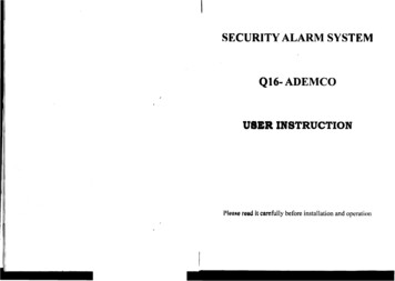
System ComponentsSystem ComponentsPanel ModelsSFC-500 SERIESSFC-500 SERIESAddressable Fire Alarm Control PanelSFC-500 SERIESAddressable Fire Alarm Control PanelAddressable Fire Alarm Control PanelSYSTEM NORMALSYSTEM NORMALMAY 21, 2006 02:41PMMAY 21, 2006 02:41PMSYSTEM NORMALMAY 21, 2006 02:41PMAC ON1COMMON ALARMCOMMON S UP VAC ON1COMMON ALARMCOMMON S UP VCOMMONTROUBLECP U FAULTGROUNDFAULT4GHI7PRS*2ABC5JKL8TUV0QZS Y S TE MRE S E TS IGNALS ILE NCEFIREDRILLBUZZE RS ILE NCEALARMACKNOWLE DGELAMPTE S TGE NE RALALARMS P ARE3XDEF6MMNO9COMMONTROUBLECP U FAULTGROUNDFAULT2ABC3AC ONX1DEFCOMMON ALARM45GHIJKL78PRSTUV6M9?4COMMON S UP PRSCP U 00-126-DRSFC-500-378-DRS Y S TE MRE S E TS IGNALS ILE NCES Y S TE MRE S E TS IGNALS ILE NCEFIREDRILLBUZZE RS ILE NCEFIREDRILLBUZZE RS ILE NCEALARMACKNOWLE DGELAMPTE S TALARMACKNOWLE DGELAMPTE S TS P AREGE NE RALALARMS P AREGE NE RALALARMSFC-551-DRSFC-551-LDRSFC-553-DRZO N E -1ZO N E -1ZO N E -1ZO N E 1-ZO N E -1ZO N E -1ZO N E -1ZO N E 1-ZO N E -1ZO N E -1ZO N E -1ZO N E -1ZO N E -1ZO N E -1ZO N E 1-ZO N E - 1ZO N E - 1ZO N E - 1ZO N E - 1ZO N E - 1ZO N E - 1ZO N E - 1ZO N E - 1ZO N E - 1ZO N E - 1ZO N E - 1ZO N E - 1ZO N E - 1ZO N E - 1ZO N E - 1ZO N E - 1ZO N E 1-SFC-553-LDRAll SFC-500 Series Panels have the following features: Multi-zone fire alarm control panel with 2 x 20 LCD display. Style Y or Style D analog loop(s). Four Power Limited Class B (Style Y) indicating circuits (max 1.7 Amps each - 5 Amps total). Dedicated common alarm, supervisory, trouble, and auxiliary alarm relays. Additional SRAX-532 Display Adders can be added to provide 64 annunciation points per adder. An optional SOCA-204 Class A converter module may be used to convert the indicating circuits to Class A (Style Z). Additional outputs include connections for a RTI remote trouble indicator, SPR-200 Reverse Polarity Module, an RS485 bus for connection of up to seven SRAM-200LCDs, SSR-212s and SRAM-300 Series annunciators. Auxiliary power is available in the form of 24V FWR unfiltered and unsupervised, 24VDC filtered and regulated, andresettable auxiliary power supply.4
SFC-500 Series Installation and Operation ManualSee the table below for the specifics of each panel.Model# ofpoints# ofloops2 line UDACT DigitalCommunicator (y/n)DoorColor# of 32 point LEDDisplaysMax # of ed02SFC-553-LDR3783yred12Some models may not be available in all markets. Verify with your local distributor.Output Class A converter: four circuits- SIG1 RET - SIG2 RET - SIG3 RET - SIG4 RET - SIG1 OUT - SIG2 OUT - SIG3 OUT - SIG4 OUT BLK REDBLK REDBLK REDBLK REDModelSOCA-204DescriptionOutput Class A converter module (fourcircuits)Polarity reversal/city tieModel -CITYTIE -POLARITYREVERSALALARMJW1POLARITYREVERSALSUPV -Polarity Reversal and/or CityTie ModuleJW2JW4SPR-200Description5
System ComponentsRemote AnnunciatorModelDescriptionSYSTEM NORMAL18:01 MON 2010-01-01SYSTEMRESETA.C. LARMSUPV2GHIPRS580ABCJKLTUVQZTRBL369DEFMNOWXY#CPU FAILENTERMENUSRAM-200LCDRCANCELINFORemote AnnunciatorModule, LCDdisplay, red paintedboxSFC-200 SERIES Remote AnnunciatorSmart Relay ModuleModelSSR-212RDescriptionSmart Relay Module(12 relays) with redenclosureSFC-200 SERIES Remote RelaySRAM-216 Remote 16SRAM-2166Description16 Zone remote annunciator
SFC-500 Series Installation and Operation ManualPanel Components and System AccessoriesMODEL NO.DESCRIPTIONSSALC-252252 Point Dual Loop Addressable AdderSRAX-53232 Zone Internal Display Adder (for SFC-551 and SFC-553 only)SRAM-208(R)8 LED Remote Annunciator (red)SRAM-216(R)16 LED Remote Annunciator (red)SRAM-316 / TZ16 LED Annunciator chassis / TZ has 16 yellow LEDs for trouble indication.SRAM-332 / TZRemote Annunciator with 32 bi-colored (red and yellow) LEDs. TZ version has 32 yellowLEDs for trouble indication.SGD-32Graphic AnnunciatorSGD-048Graphic Annunciator Adder Driver BoardSRTI-200Remote Trouble Indicator, Buzzer and LEDSFC-200TRBTrim Ring For Enclosure (Black)SFC-UNIV-TRBTrim Ring For Larger Enclosure (Black)SBB-301(R)Enclosure for one annunciator, white. R version is red.SBB-302(R)Enclosure for two annunciators, white. R version is red.SBB-303(R)Enclosure for three annunciators, white. R version is red.SBB-308(R)Enclosure for eight annunciators, white. R version is red.SBB-312(R)Enclosure for twelve annunciators, white. R version is red.MP-300End-of-line resistor plate, 3.9K ohmBC-160External Battery Cabinet7
System ComponentsAnalog/Addressable DevicesDESCRIPTIONSummit ModelIonization Smoke Detector (UL Listed)SII-200Photoelectric Smoke DetectorSIP-200* Multi-sensor (photoelectric with supplemental rate-of-rise heat sensor)SIM-200Heat DetectorSIH-200BASES4 inch Standard BaseSIB-46 inch E-Z Fit BaseSIB-66 inch Base with RelaySIB-6R6 inch Base with SounderSIB-6S6 inch Base with Temporal Tone SounderSIB-6THANCILLARY MODULESPriority Monitor ModuleSIM-100PMini Priority Monitor ModuleSIM-101PSingle Relay Output Module (1 Form C Contacts, 2 Gang Mount)55000-820Supervised Control ModuleSIM-100SSIM-100X (Kit)Isolator c/w Mounting Base100XH (Isolator)100XB (Base)ADDRESSABLE DUCT DETECTORSIonization Duct Smoke Detector (UL Listed)SIDH-200IPhotoelectric Duct Smoke Detector (UL Listed)SIDH-200PIonization Duct Smoke Detector with relay (UL Listed)SIDH-200IRPhotoelectric Duct Smoke Detector with relay (UL Listed)SIDH-200PRADDRESSABLE PULL STATIONS*Addressable Single Stage Single Action Pull StationSPS-201IDAddressable Single Stage Dual Action Pull StationSPS-202IDUnit employs an integral heat sensor; however it must not be used as a regular heat detector. Refer to theproduct data sheet for detailed functionality, operation and application.Manual configuration for the SIM-200 is NOT PERMITTED. This device must be configured via the AUTOCONFIG.8
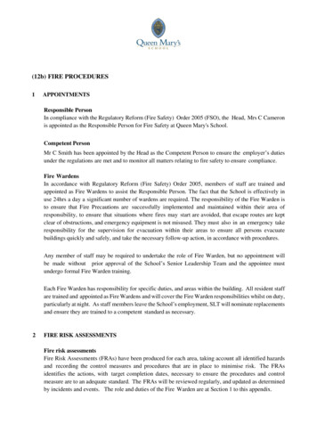
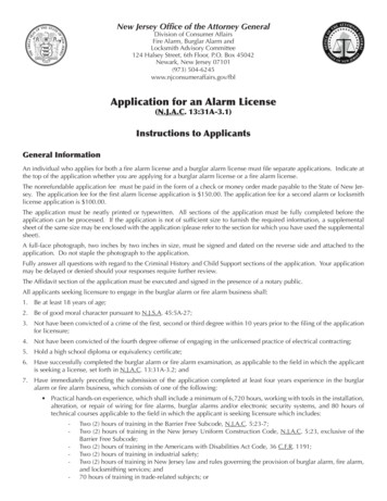
SFC-500 Series Installation and Operation ManualMechanical InstallationInstalling the EnclosureInstall the SFC-500 Series Fire Alarm Panel enclosure as shown below. Mount the enclosure using the four mountingholes and the screws provided.Figure 1: Wallbox Dimensions / Mounting the SFC-500 - ting Hole5.4"Mounting Hole4.5"14.5"9
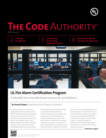
Mechanical InstallationFigure 2: Mounting the SFC-500 - Flush11"1.5"PLACE SFC-200TRB TRIM RING OVER BACKBOX17"4 MountingHoles forSurfaceMounting14.5"Adhere trim ring towall surface aroundSFC-500 backbox20.0"22.5"3.5" is the maximum depthfor semi-flush mountingusing the flush trim ring4"5"4. 3.5"1"14.5"1" is the minimum depthabove the wall requiredfor semi-flush mountingusing the flush trim ringFigure 3 shows a cross-section of the semi-flush mounted backbox and the trim ring. Make sure to allow aminimum depth of 1” above the wall surface for proper door opening.Figure 3: Flush Trim DetailTrim ringWallWood stud10Back box
SFC-500 Series Installation and Operation ManualFigure 4: Wallbox Dimensions / Mounting the SFC-551/SFC-553 – Surface /Flush11"PLACE SFC-UNIV-TRB TRIM RING OVER BACKBOX17"1.5"4 MountingHoles forSurfaceMountingAdhere trim ring towall surface aroundSFC-551 backbox20.5"26"28.5"3.5" is the maximum depthfor semi-flush mountingusing the flush trim ring4"5"4. 3.5"14.5"1"1" is the minimum depthabove the wall requiredfor semi-flush mountingusing the flush trim ringNote: See Figure 3 for Flush Trim Details for mounting the trim ring.11
Installing Adder ModulesInstalling Adder ModulesThe SFC-500 Fire Alarm panels come pre-assembled with all components and boards except for Adder Modules.Module installation locations are shown in Figure 5. Refer to Figure 6 on the next page for Jumper or DIP Switchsettings and see Wiring Tables and Information for wiring specifications.Figure 5: Installation of Adder ModulesJW3RS-232C PORT LoopA-B JW4LINE2COSYSTEM NORMALRESTRT-RESRTLINE1RCOTFor PC programming use UIMAInterface module not UL-864 orULC-527 listed. Please refer toDocument LT-929 for detailsROCT 21 , 2005 SUPPLY- SIG1 RET - SIG1 OUT - SIG3 RET - SIG4 RET - S
Note: Installation of the SFC-500 Series Fire Alarm Control panel should be in accordance with Canadian Electrical Code Part 1, ULC-S524 installation of Fire Alarm System, National Electrical Code NFPA 70 and NFPA 72. Final acceptance subject to the Local Authority Having Jurisdiction (AHJ).