Transcription
Operator Training Manual
Operator Training Manual Version 1.0Table of ContentsSafety . 2Print Setup . 71) Main Knife Alignment . 82)Eccentric Knob Adjustment . 93)Total Print Adjustment . 104) Engaging and Gaging Necessary Print Stations . 105) Plate Mounting . 126) Plate Alignment . 157) Ink . 178)Guards . 199) Start Machine . 1910) Dialing Stations . 1911) Print Inspection . 2012)Supervisor Inspection . 21Size Change Procedure . 23Machine Cleanup Procedure . 30Print Station Cleaning Process . 311‐Hour Clean‐Up . 344 Hour Clean‐Up . 37Machine Terminology . 40Appendix A . 49Safety Signoff Documents . 491
Operator Training Manual Version 1.0Safety2
Operator Training Manual Version 1.0Mission StatementProtecting the health, safety and security of our employee and those who work on ourbehalf is a core value for TULSACK. We believe in Zero Harm workplaces, where all incidentsare preventable.This is our Safety and Occupational Health Policy. Although all employees know andunderstand this policy, TULSACK machine operators inherit the responsibility of running a crew.It is important that all machine operators realize that their demonstration of safe work habits areimportant to the success of the overall safety program. In order to reemphasize this, we haveput together some important safety reminders within this Operator Manual, which are critical tobecoming and continuing to be a TULSACK machine operator.Job Description for Bag Making / Inline Printing Machine OperatorDepartment: ProductionJob Status: Full TimeFLSA Status: Non-ExemptReports To: Shop SupervisorsGrade/Level:Amount of Travel Required: No travel requiredWork Schedule:Positions Supervised:Currently: 5 days per week @ 8 hours per shift.Note: with over time as required.A machine operator at Tulsack is responsible forsupervising a 2‐person crew (catchers) that areassigned to his/her machine.Position Summary:Set up and/or operate various types of bag making machines as well as flexographic printing machines toproduce print on the retail paper shopping bags that are being manufactured.Essential Functions:Reasonable Accommodations StatementTo perform this job successfully, an individual must be able to perform each essential duty satisfactorily.Reasonable accommodations may be made to enable qualified individuals with disabilities to perform theessential functions.Essential Functions Statement(s)3
Operator Training Manual Version 1.0 Inspect and examine printed products for print clarity, color accuracy, conformance tospecifications, and external defects. Reposition printing plates, adjust pressure rolls, or otherwise adjust machines to improve printquality, using knobs, handwheels, or hand tools. Examine job orders to determine details such as quantities to be printed, production times,stock specifications, colors, and color sequences. Select and install printing plates, rollers, cylinders in machines according to specifications,using hand tools. Monitor feeding, and printing process to maintain specified operating levels and to detectmalfunctions, making adjustments as necessary and notifying a supervisor of any problems. Operate equipment while maintaining the minimum bag speed and ensuring the quality, properink coverage, alignment, and registration. Notify a supervisor immediately of all needed repairs. Immediately notify a supervisor or manager, any instances of insubordination, improperbehavior or performance problems regarding his/her crew. While wearing the proper protective equipment, clean and lubricate machines andcomponents, using oil, grease, WD40, brushes, rags, hoses, and compressed air. Move all heavy or awkwardly packaged materials, using hand trucks, forklifts, or hoists, totransfer them to finishing or designated areas. At all times, Follow ALL safety rules/regulations contained in the TULSACK employeehandbook. Direct and supervise the activities of workers, inspecting, and packaging the productmanufactured on their assigned machine. Monitor stocks of materials such as paper, ink and glue to maintain supplies during equipmentoperation. Change bag size by using specific tools and written standards for size changes. Maintain records of goods produced and waste accumulated during his/her shift. All waste is tobe weighed each hour and signed-off and by an Adjuster, Supervisor, or manager only! Machineoperators MUST immediately notify an Adjuster, Supervisor, or manger, anytime his/ her wastepercentage has reached the specified “Maximum” level for that specific hour of production runtime Requisition supplies, materials, and equipment and receive stock. Supervise and assist as needed, the packaging of bags and labeling of cartons, boxes of finishedproducts to maintain quality standards and reduce waste. Place spools twine or paper, and thread through machines.4
Operator Training Manual Version 1.0Moving Machinery SafetyPotential hazards of operating machines and equipment are numerous. Some of the most obviousrecognized hazards are from machine motion. Hazardous motion is characteristic of the point-ofoperation of the machine, but can also be found in other areas such as behind, to the side, or above amachine. Rotating motion of collars, couplings, cams, clutches, shaft-ends, set screws, spindles, etc.,can be dangerous by gripping clothing or forcing arms/hands or other body parts into dangerouspositions. Rotating parts can also create nip points when two adjacent moving parts are in close proximity(e.g., two cogs, two rolling bars, gears, chain and sprocket, etc.); or a rotating part is in close proximity toa fixed point.The following applies to all Tulsack Production employees: Do not touch or reach over moving or rotating machine parts. As per the Dress Code: No Rings, Watches, loose sleeved clothing. Do not attempt to override or defeat safety features. Guards and shields must be in place duringnormal operation. Observe appropriate Lockout/Tagout procedures when guards, shields, orother safety devices are removed or deactivated for maintenance or repair. Do not operate a machine outside of the scope of your abilities, even if it is within the machine’soperating limits. Communicate with others that may be working or occupying space near-by to avoid humaninduced hazards (e.g., when inching the machine alert or instruct each other, etc.). Report near-misses or close-calls (an incident where no property was damaged and no personalinjury sustained, but where, given a slight shift in time or position, damage and/or injury or illnesseasily could have occurred) to your Supervisor and Safety Coordinator. Know the emergency stop/shut-down procedures for the specific machine operated. Inspect machines/equipment prior to each operating shift to ensure that:oPoints of operation and surrounding areas are clean of debris and other hazards.oShields and guards are in place and controls and interlocks or other safety devices areaccessible and operating properly (pay attention to the point of operation, as well as thearea behind, and to the side of the machine).oMachine components are in good working condition (do not use damaged equipment).oLabels and warnings are present and legible.oMake yourself aware of all stop buttons locations (Stop the machine immediately ifanything unexpected happens).5
Operator Training Manual Version 1.0Operator Safety Signoffs- During the early stages of your training, the Safety Coordinator and/orTraining Supervisor, will review the following training topics and retain the signed documents in youremployee file. It’s important to know that each of these topics are directly related to an injury incident andare for your protection as an employee. Reaching into running machinery Plate Marks Print Cylinder Guards Cleaning Print Plates on Machine Resin Roller GuardingPre-Use Inspections of chain hoist equipment- During normal machine operations it isnecessary for your crews to use the chain hoist in changing out the print cylinders. It’s recommended tocheck that the pre-use inspections are being performed by your crew and that proper procedures arebeing used to change out any cylinders or rolls.Mill roll Shaft lock pin- Several of the machine mill roll carriages have been retrofitted with a MillRoll Shaft lock pin. These were added to prevent injury from the mill roll shaft coming loose of thecarriage and falling from the machine. It is required that these pins be replaced after each mill roll changeand maintained as they are a machine guard.Cut Gloves Usage- Tulsack provides cut resistant gloves for your use while maintaining themachines. It’s mandatory that they be used during the changing out of all blades and/or knives on themachines. When using a fixed or folding blade knife, a cut glove must be worn on the opposite hand ofthe knife while cutting. Listed are specific components that require the use of cut gloves while beingreplaced: Main Knife Blade Slitter Blade Dipper/Tucker Blade6
Operator Training Manual Version 1.0Print Setup7
Operator Training Manual Version 1.01) Main Knife Alignment1.1 Align arrows on the main knife or set to the home position. Alignment of the mainknife is done first in order to establish a set reference point for the entire printingprocedure. Alignment can be achieved by the following two methods.1.1.1Inch machine Hold alarm button for 3 seconds, let off alarm button and hold inchbutton until desired position is reached, then release button.Repeat process if necessary.1.1.2Hand Wheel Pull wheel out and rotate clockwise to move machine forward. Push wheel back in.8
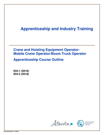
Operator Training Manual Version 1.02)Eccentric Knob Adjustment2.1 Eccentric Knob Adjustment:2.1.12.1.2Center Up/Down eccentric adjustment knobs. Clockwise moves the print down Counterclockwise moves the print upUnlock the eccentric adjustment knob by rotating lock ringcounterclockwise.2.1.3Adjust the gap between the lock ring and knob to approximately11/8”. (Note: This establishes equal travel in either direction.)1 1/8”2.1.4Tighten locking ring by rotating it clockwise.9
Operator Training Manual Version 1.03)Total Print Adjustment3.1 Center total print adjustment.3.1.1Align mark on total print adjust gear with the mark on the frame of themachine. This establishes overall up and down print registration.4) Engaging and Gaging Necessary Print Stations4.1 Engage and gage necessary print stations.4.1.1Reusing a previous station set: Use print roller gage to gage station in order to preventcrushing the sensitive print plates.4.2 Screens or small print jobs.4.2.1Engage print station.10
Operator Training Manual Version 1.04.2.2Ensure all locks are loose and place print roller switch in the “Down”position.4.2.3Place printer wrench on the engage bolt and rotate the handle clockwiseto slide the print station into engaged position.4.2.4Ensure print roller gear is in mesh with backup roller gear and anilox gear.11
Operator Training Manual Version 1.04.2.5Tighten lock knobs for ink to plate and plate to paper adjustment.4.2.6Place gage on handle side in gap between print roller and backup roller. If too close: dial out print cylinder slowly until gage fallsthrough If too far apart: dial in print cylinder until gage is pinched,then slightly back out enough to remove gage4.2.7Repeat process for all four sides of the roller.5) Plate Mounting5.1Mount plates on cushion back.5.1.1Roll out enough cushion back to place plates on.5.1.2Place plate on cushion back and peel plate back halfway. Roll plate ontocushion back to prevent air bubbles from being trapped between plate12
Operator Training Manual Version 1.0and cushion back.5.1.3Peel off other side of plate and repeat process.5.1.3Cut around plates using box knife, leaving ¼ inch on all sides except thebottom.Always Wear Kevlar Gloves when using knives.5.1.4Cut bottom portion of cushion back evenly with plate to prepare formounting. (Note: Never cut a plate or poke holes in a plate without gettingapproval from a supervisor.)5.2 Mount plates on rollers5.2.1Loosen gear side print roller (may occasionally hear it called the plateroller) adjustment bolt.13
Operator Training Manual Version 1.05.2.2Roll print roller to usable horizontal line and place bottom of plate onhorizontal center line while maintaining alignment with vertical center lineon the print roller. (Tip: When mounting large plates, remove only bottomhalf of cushion backing to prevent the top of the plate from sticking to thepaper.)5.2.3First place one side down, then slowly lower the rest of the plate onto theprint roller. Slowly roll on plate while smoothing plate onto cylinder toprevent bubbles from being trapped between the cushion back and printroller.5.2.4Ensure the vertical center line is aligned with the vertical center line onprint roller. If not, adjust accordingly. (Note: The vertical line is the mostimportant line to register correctly.)14
Operator Training Manual Version 1.05.2.5Eliminate air bubbles by using hand to smoothen plate.6) Plate Alignment6.1.2Loosen the print roller adjust bolts15
Operator Training Manual Version 1.06.1.3Align the horizontal center line with the handle side marker.6.1.4Place magnetic marker on gear side of print roller in the 12 O’clockposition.16
Operator Training Manual Version 1.06.1.5Rotate print roller to station and size specific setting.6.1.6Tighten print roller adjustment bolt.6.1.7Remove magnetic marker from print cylinder7) Ink7.1 Install and engage ink tray.7.1.1Place ink tray on the platform.7.1.2Engage ink tray by rotating the engage lever towards the ink station until the inktray hits the bottom of the rubber roller.7.1.3Lock ink tray in place by holding the engage lever and pushing the lock leveraway from the ink tray lock mechanism.17
Operator Training Manual Version 1.07.1.4Pour ink into tray until ink level slightly exceeds rubber roller.7.1.5Nip anilox:I.Turn on agitation for the station.II.Nip anilox by rotating adjust knob clockwise.III.Turn handle side adjustment knob 2 full rotations.IV.Turn gear side adjustment knob 2 full rotations.V.Repeat process until no thick ink is visible on anilox roller. (Note:Alternating between sides will prevent one side from being nipped tootight.)18
Operator Training Manual Version 1.0VI.Tighten nip roller locking knob8)Guards8.1 Install all guards on printer and lock guards in place by rotating knobs clockwise.9) Start Machine9.1 Start machineI.Hold alarm bell for 3 seconds or until start button illuminates.II.Press start button.III.Turn seam glue switch to on position and hold fast button untilmachine speed reaches 60 bpm.10) Dialing Stations10.1Dial in all stations10.2Dial out ink to plate using ink to plate adjustment knob.10.3Dial out handle side and gear side evenly until no ink is being transferred thenslowly dialback in both handle and gear side evenly until full image is printing.10.4Repeat process for plate to paper using plate to paper adjustment knob.10.5When printing is at full operation, lock station using print station locking knob.19
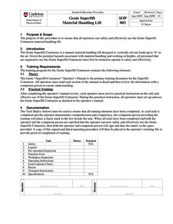
Operator Training Manual Version 1.011) Print Inspection11.1Grab fresh bag from front of the machine.11.2Compare bag to Production Proof and make adjustments accordingly.11.3Adjustments can be done using the following methods:11.3.1 Eccentric adjustment (Up and Down adjustment):I.Adjust eccentric knob to align registration from station to station.PrintMisalignment11.3.2 Side to Side adjustment:I.Unlock knob by pushing lock lever counterclockwise.II.Rotate clockwise to move print gear side. Rotate counterclockwiseto move print handle side.20
Operator Training Manual Version 1.0III.Lock by rotating lever counterclockwise.11.3.3 Overall Up/Down print adjustment:I.Unlock overall print adjustment by turning lock counterclockwise.II.Rotate overall print adjustment knob clockwise to move the wholeprint up.III.Rotate counterclockwise to move whole print down.IV.Lock overall print adjustment knob by turning print adjustment lockknob clockwise until tight.12)Supervisor Inspection12.1Fill out print approval on traveling work order for the operator position.12.2Take folder and approval bag to supervisor for final print approval.21
Operator Training Manual Version 1.022
Operator Training Manual Version 1.0Size Change Procedure23
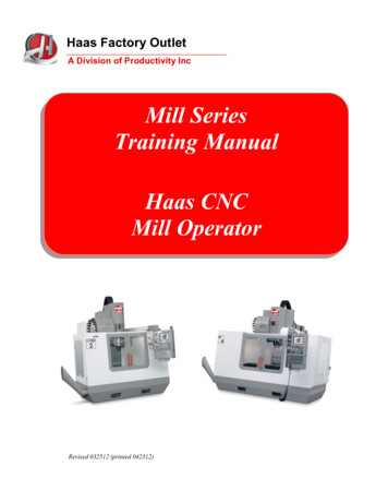
Operator Training Manual Version 1.0Bag SizeGearCut offLengthCenter Gripto JawDistance16 x 6 x 1241 Tooth41010513819816 x 6 x 1650 Tooth50010413819816 x 6 x 1959 Tooth59010513819813 x 7 x 1755 Tooth55011816416113 x 6 x 1650 Tooth5009713816118 x 7 x 1859 Tooth59013316422310 x 5 x 1342 Tooth420871111228 x 5 x 1035 Tooth350871119814.5 x 9 x 16.2555 Tooth5501302151799 x 6 x 1444 Tooth44010413810710 x 7 x 1242 Tooth42010816412213 x 7 x 1344 Tooth44010816416110 x 5 x 1035 Tooth350961111225x3x856 Tooth28061726512 x 7 x 1242 Tooth42010616314812 x 7 x 15.7551 Tooth510106163148Jaw to JawDistanceSide Gripperto Centerline24
Operator Training Manual Version 1.0Desired ChangeFollow These StepsDifferent Bag Length3,4,8,16,21,23‐29Different Bag 29Different Bottom th and Width1,1a,2,3,5,6‐9,11,13‐15,18‐29Complete ChangeAll Steps,1‐29Paper Bag Width and DefinitionsStep 1) Change the mill roll and position the roll by adding half the face, one gusset, and one inch. Thenadd the same dimensions of the bag you are changing to. Take the difference and move the roll from theprevious spot on the shaft towards/away from the guide collars on the handle side.1a) Install Timing Gear for print stationsStep 2) Move the gear side of the handle feed section. To get the right measurements use the paper bagwidth diagram and add half the face, one gusset, and half the back of the bag you are change to. Takethis measurement and measure from the center of the handle feed tracks. Move the gear side until youget the right measurement. Use gauge if available.Step 3) Set the speed of the patch paste pads. Jog the machine until the pads are on the backup roller.Then loosen up both gears and set the gauge one number less than the cutting gear you are changing to.Step 4) Set the speed for the perforation knives. Jog the machine until the knives are on the backuproller. Then loosen up both gears and set the gauge to the number cutting gear you are changing to.Step 5) Change the former, and set the former guides and rollers to the former.Step 6) Set the gusset wheels by measuring from the inside tip of the wheels closest to the draw roller,to the outside edge of your former one half your gusset size minus 1/8”.Step 7) Move draw rollers so the draw rollers are covering about three quarters of the tube and aquarter is not. Unless you’re running the minimum width bag then just move to avoid the handle.Step 8) Change cutting gear and set the speed of the cut off knife by using the gauge or mark on thegauge of the knife. Set the gauge at the same number as the cutting gear.Step 9) Move the pinch rollers, snap off segments, and score segments to the center of the gussets.Unless you are running the minimum size width then just move these units away, from the handle.25
Operator Training Manual Version 1.0Step 10) Set the score blades to half the size of the bottomStep 11) Move the opening cylinder to the correct width; the same size as your bag.Step 12) Change stretch cams and/or opening cylinder cams. Then move the inside cam that raises upyour gripper and set the cam so the grippers raise and slide off the bag at the same time. When startingthe machine up at the slowest speed at the end of the change increase or decrease stretch dependingon the bottom size.Step 13) Move the forming shoes to the correct width.Step 14) Remove the tucking blades and set the side grippers by measuring from the scribed center lineto the tip of the gripper, half your bag width minus 4 mm. Then move and/ or open vacuum holes onehole in from the tip of the grippers.Step 15) Move the ironing guides 4mm to the inside of your side grippers, or as close as your bottompaster allows.Step 16) Move the center gripper(s) by measuring from the tip of the gripper to the front jaw minus4mm. The right measurement is 70% of the bottom width you are changing to.Step 17) Open the jaw to jaw to the right width bottom you’re changing to. Measure from front jaw toback jaw minus 8mm. When doing just a bottom width change remove back tucking blade.Step 18) Replace the front tucking blade with the same width as your bag and slightly round the cornersso the blade can avoid the side grippers when it enters the jaw.Step 19) Reinstall the back dipper blade and set the blade 2mm from the stationary jaw of the jaw.Step 20) Change the bottom paste pads.Step 21) Thread the paper through the machine all the way up to the draw roller and have someone rollthe paper. Do not let the paper go through the machine until you are ready to time it up.Step 22) Before you set the gusset width make sure the gusset wheels’ nest to the draw rollers are snugwith the paper. Check this while the machine is running at its slowest speed. Then check the gussetwidth and move if necessary. Then set the former guides to smooth the paper out.Step 23) Set the snap off segments to grab the tube as the cutting knife enters the slot. Then set thepinch rollers to release the tube when the snap off segment have the tube.Step 24) Adjust the tube to the center gripper to grab 4mm.Step 25) Push the start button and run the machine at the slowest speed to set the perforation evenwith the cutting knife. This is adjusted with the total differential button.Step 26) Start the machine at the slowest speed and make sure everything is lined up properly.Step 27) Line up the patch resin pad with perforation.Step 28) Line up the patch handle with the resin.26
Operator Training Manual Version 1.0Step 29) Start the machine up slow and make sure everything is lined up properly then graduallyincrease the speed.27
Operator Training Manual Version 1.0Parts Needed to do the Changes1) For cutting length change, each tooth on the cutting gear is equal to 10mm. For example, 35NTgear is equal to 350 mm cutting length.2) For width changes, the forming plate should be equal the width of the bag minus 1/8”. Forexample, on a 8” wide bag, the former should measure 7 7/8”.3) Fore width changes, the tucking blades should be the same width as your bag. The front bladeshould be slightly rounded on the corners to avoid the side grippers when entering the jaw.4) For bag width and bottom width changes, the bottom paste pad should be changed according tothe size. Check the cutting table for pattern.5) For bottom width change, replace the side cam of the opening cylinder and/or stretch cams tomatch the bottom width if necessary.*Always put ink on the plates by using the “Ink to plate knob” before adjusting the plates to the paper.* To increase ink on the plates, turn the knob clockwise (right)To decrease, turn the knob counter clockwise (Left)This should be done in small turns on alternating sides of the printer to ensure even application of ink.*One ink has been evenly applied to the plates, begin dialing the plates to the paper using the same smallturns on alternating sides of the printer. This will ensure an even amount of pressure on to the paper.28
Operator Training Manual Version 1.0Forming Table Measurements(From Former to the edge of the table)12"13"14.5"16"18"8"10"13"NL1330mm H/S318/361 mm300 mm H/S280/321 mm255 mm H/SNL8303.5 mm278 mm240 mmNL410"13"8"278 mm241 mm303.5 mm18"14.5"13"16"14"12"NL5276 mm320 mm340 mm302 mm327 mm352 mmNL912"10"8"13"8‐3/4"253 mm278 mm303.5 mm241 mm294.5 mmAutomatic Former on NL 3WARNING!! Before you reset the former and gussets, make sure everything is out of the way. Bars,Wheels, etc 1. Set to “Origin” and Push Start.2. Set to “Data” and enter the correct size in (mm), push and hold “Start”. The start button willlight up and go out.3. Set to “POSI” and start.9"14.5"13"6"18"10"4‐7/8"8"16"NL3228.8 mm368.3 mm330.2 mm152.4 mm457.2 mm254 mm123.8 mm203.2 mm406.4 mm29
Operator Training Manual Version 1.0Machine Cleanup Procedure30
Operator Training Manual Version 1.0Print Station Cleaning Process1.1Attach spout and then attach the hose to spout. Put the hose in the ink bucket.1.2Disengage the ink tray and place mill roll core under gear side of tray in order toplace tray on a gradient.1.3Open valve to let the ink flow out through the hose. Use paint spatula to help inkcirculate out.1.41.5Switch hose from paint bucket to water bucket.Spray anilox completely with soap and then scrub anilox using steel brush. Scrubin a circular motion until roller has been completely scrubbed. (Note: Start on thehandle side and continuously spray anilox with soap while scrubbing to ensureproper cleaning and to minimize possible damage of anilox roller.)31
Operator Training Manual Version 1.01.6Rinse steel brush and paint spatula with water in the water bucket.1.7Rinse the anilox roller with water until it’s completely clean.1.7 Turn off anilox and tilt tray to drain water.1.8 Close valve and remove hose, spout, and mill roll core.1.9 Remove the tray and take and give to catcher to wash in the washroom.32
Operator Training Manual Version 1.01.10Wash the ink tray thoroughly.1.11Un-nip the anilox.1.12 Loosen gear side bolts and remove the plate from the roller.1.13Tighten gear side bolts1.14Remove sticky back from plate (Do not leave plates on the roller or stuck to thecushion back).33
Operator Training Manual Version 1.01‐Hour Clean‐Up1) Shut down machine. Break web and inch machine until paper is clear of the forming table.Inch machine again until the resin applicators are in a cleanable position.Turn off all clutches. On all machines except N/L 138s, work with the packaging inspector totoggle machine lock out switch while you’re cleaning the front end. It is the operator’sresponsibility to make sure the machine lock outs are being used. On machines that lock outshave not been installed, push an emergency stop button.2) Take handles down and clear the handle section of handles. Turn off resin switches or valvesand the hot melt pump. Immerse 4” resin head in water. Disengage the slitter from machine.Run paper and twine out of unit.34
Operator Training Manual Version 1.03) Inspect and clean handle delivery section.4) Clean forming table and immerse seam glue head in water.5) Run paper out of the front end.a) Clean all draw rollers, segments, and brass plates (if there is glue build up) up tomain drum.b) Scrape paste off the main drum surfaces and clean with cleaning solution andscouring pad.35
Operator Training Manual Version 1.0c) Scrape paste off dipper blades and holders.d) Blow out entire machine. Then apply a liberal amount of WD‐40 to all the rollers,segments, shafts, main drum and dippers.e) Web up front end.6) After slitter is cleaned:a) Change slitter blade at this time if necessary. Be sure to turn off slitter blade and wearKevlar gloves while changing the blade.b) Install cleaned resin pans and roller scrapers (if applicable).c) Run handles to the pin wheels and engage slitter.d) Start machine and make adjustments to the amount of resin being applied to handles.7) Run Ma
Rotating parts can also create nip points when two adjacent moving parts are in close proximity (e.g., two cogs, two rolling bars, gears, chain and sprocket, etc.); or a rotating part is in close proximity to a fixed point. The following applies to all Tulsack Production employees: Do not touch or reach over moving or rotating machine parts.