Transcription
123WaxRing documentationThe 123WaxRing Wizard and the 123WaxRing fixturemake it easy to create wax models for jewelry manufacturing purposes.www.123waxring.comwww.deskproto.comPatent pending.Copyright 2009-2012, Delft Spline Systems.123WaxRing (tm) and DeskProto are trademarks of Delft Spline Systems.Delft Spline Systems ,PO. Box 2071 , 3500 GB Utrecht ,The Netherlands.
Contents.I.Features and advantages.4II.Installation and d itemsMounting the 123WaxRing fixture .The workpiece zero point.Setting the zero point on a Roland .Setting the zero point on a non-Roland .Fine-tuning the zero point (optional).Some additional notes.Software Setup.Creating a wax model.III.1III.2III.3Running the 123WaxRing Wizard.Machining a wax ring .The 123WaxModel Wizard.66781011141416161720Appendices.A.1A.2A.3Wax Block specifications.Fixture mounting specificationsAdapter for Sherline type machines3222324
I.Features and advantages.The 123WaxRing system is a combination of CAM software and a fixture that makes itvery easy to machine wax models of complicated ring designs. The software is a wizardthat runs in the DeskProto CAM program. The fixture is a high accuracy aluminumpiece, designed to be used on the rotation axis unit of the Roland JWX-10 Jewela CNCmilling machine. It can very well be used on other machines, though an adapter may beneeded.In order to use the 123WaxRing system you need to have:- a 3D CAD system to create your ring designs. All current CAD programs for jewelersare supported, like 3Design, JewelCAD, Matrix, Rhino, TechGems. and many others(geometry import as STL file).- a CNC milling machine with a rotation axis. The fixture has been designed for aRoland machine (JWX-10 or MDX-40), still other machines can be used as well usingan adapter. See the example in paragraph II.1.- pre-shaped wax-blocks as delivered with the fixture. You are also perfectly free tocreate your own wax blocks.- a cutter. We are enthusiastic about conical cutters (for instance as offered bybitsbits.com): they combine a long cutting length with a very small tip. Other cutterslike flat and ballnose can be used as well.The principle of the system is very simple:1. Machine side 1, standard XYZ machining.2. Turn the block upside down and machine side 2, standard XYZ machining.3. Machine the outside of the ring using the rotation axis (XZA machining).All three steps can be done with the same workpiece zero point and with the samecutter.In the center of the ring a cylinder wax support block will remain un-machined, thecore, that is used to fixture the model in all three orientations. The wizard will preparethe toolpaths for you: you only need to place the wax block three times, the rest is doneautomatically.Advantages:- Wax models with undercuts can be created by machining from several sides (in4
several orientations).- For all orientations the model is clamped on the same fixture, resulting in a very highaccuracy. No need to change or adapt the fixture.- The fixture is very stable: no assembly where the parts can move and introducepositioning errors, no vibrations during machining. This will result in a superb surfacequality.- No need to change the cutter: all milling can be done with a conical cutter(competing systems also need a straight cutter to machine the core).- All orientations are done with the same workpiece zero point. So this needs to beset only once !!- As a result the system is very easy to use: take a block, fixture it with just one screwand start machining.- The system also is very fast: preparing the toolpaths and machining will take less timethan with competing solutions.- Minimum loss of wax: no oversized wax blocks are needed for clamping purposes.- The positioning of the reference pins is such that the wax block cannot be incorrectlypositioned. Only for step three there are two options, and the wizard has added an extratoolpath to prevent error here.- After completing the wizard all DeskProto parameters are available to fine-tune yourparameters. In most cases this is not needed, still this flexibility makes more complexpieces possible too.- DeskProto offers an automatic feedrate reduction in high chip load situations.- The wizard is written in a simple script language, so it is editable: any skilled usercan change and/or elaborate the wizard when needed.- The toolpaths are completely prepared by the wizard: no need to manually selectmacros for special functions that need to be performed (like machining the core).- The toolpaths can be sent directly to the Jewela machine from DeskProto: no need tosave an NC file first and then use a separate program (Dropout) to send them to themachine.- On the Jewela machine the fixture can be used with the rotation axis unit in therightmost of the two possible positions. So the small orange table on top of therotation axis can be used for XYZ milling as it is within the working area. This meansthat both XYZ machining and rotation axis machine are possible without reconfiguringthe machine.- It also is not needed to change the BIOS of the Jewela machine: it can be used “as is”.- The same fixture can also be used for two-sided milling (pendants, brooches etc). Seethe chapter on the 12WaxModel Wizard. So changing fixtures is not needed.When compared to making a wax model using an additive process (sometimes called 3Dwax printing) advantages of the 123WaxRing system are the better surface quality of themodel, and the ability to also process STL files that do not contain a perfect solid.As so many innovative new features are incorporated in this system, the 123WaxWizardis protected by a patent (pending).5
II. Installation and Setup.II.1Included itemsPlease find included in your 123WaxRing kit the following items:1 x 123WaxRing fixture3 x hexagonal mounting screw (size M4 x 10 mm)3 x hexagonal screw for mounting wax blocks (size M4 x 16, 20, 25)3 x washer size M42 x Conic 123WaxRing cutter (shaft diameter 3.175 mm, included angle 20 degr, flat tipwith diameter 0.1 mm). This is "Bits & Bits" cutter No. 815-PR20/.0048 x round wax disk 10 mm thick3 x round wax disk 15 mm thick2 x round wax disk 20 mm thick3 x square wax block 10 mm thick1 x 123WaxRing documentation.II.2Mounting the 123WaxRing fixture on yourmachine.On the Roland JWX-10 en MDX-40machines the fixture can be directly attachedto the rotation axis using three screws. Seethe Roland documentation for moreinformation. Note that first the Sensor partneeds to be mounted on the rotation axis, inorder to find the Y 0 position. After that the123WaxRing fixture can be attached.On many USA-made machines a Sherlinetype rotary table is present. For thesemachines we offer the “Sherline-to-Rolandadapter”: see Appendix A.3 of this manual6
On other machines it may be possible to clampthe adapter in a 3-jaw chuck or 4-jaw chuck onit’s rotation table. The fixture can be clampeddirectly, or an adapter can be used to createsome distance between waxblock and chuck.The Sherline adapter just mentioned can verywell be used for this purpose. Attach the fixtureto the adapter and mount the combination in thejaws of your rotary table’s chuck. See theillustration that shows adapter and fixturemounted on the rotary table of a Taig machine(picture courtesy of caducopia.com).When mounting the fixture you need to make sure that:1) the axis of the rotary table (A) is perfectly parallel to the X axis of the machine.2) the fixture/adapter is being held perpendicular to the rotary table.3) the adapter is properly centered in the chuck, i.e. the axis of the fixture/adapter iscoincident with the A axis. With a four jaw chuck like shown in the picture an eventualoffset can be corrected.For more information see the mounting specifications in appendix A.2II.3The workpiece zero point.Setting an accurate WorkPiece zero point is the key element in order to create accuratewax models with the 123WaxRing system. This is true for all 4 axes involved: X, Y, Zand A. An error as small as 0.1 mm or 0.1 degree will be visible in the resulting model.Note that accuracy is relative: an error of a few 1/100 mm is acceptable as this will alsobe the tolerance of the machine. A toolmaker will find this a very low accuracy, for aring model it will be OK.As you will see setting the zero point is a complex procedure, without the ease of usethat was promised for the 123WaxRing system. Allow yourself at least an hour for thisprocedure, even more when you use an adapter. Note that this zero setting needs to bedone only once. You can ask your reseller to do so for you after installing the system.Then you can skip this paragraph and start milling a ring model. And that will be veryeasy, as promised.7
The illustration above shows the 123WaxRing fixture and the position of the WorkPieceZero point (WP zero). The fixture is accurate within 0.001 mm, so any inaccuracies willbe caused by the zero point setting or by the machine.The workpiece zero point needs to be set as follows:Y, Z 0 - on the rotation axis. For Z the tip of the cutter counts.X 0 - at the right side of the fixture (at the vertical fixturing surface)A 0 - with the top surface (the horizontal fixturing surface) horizontal.So the zero point is on the rotation axis at the right end of the fixture (not counting thereference pins), see the red crosses in the illustration above.The horizontal surface is 8 mm higher (8 mm along Z), and its center hole there is 18mm left of the zero point (18 mm along X). The 123WaxRing Wizard in DeskProto willautomatically create all toolpaths relative to this one zero point. Also the toolpaths forSide 1 and 2: changing the zero point is not needed.II.4Setting the zero point on a Roland machine.The Roland JWX-10 and MDX-40 machines feature an automatic zero findingprocedure for Y and Z. You need to zero the Y axis first, as only after that the fixturecan be mounted, which is needed to zero X and A.Setting Y 0:The standard procedure of the Roland machine may be followed:- Install the sensor on the rotation axis and connect the sensor cable to the sensor.- Insert a cylindrical shape that is sufficiently long in the collet chuck.- In the Roland JWX-10 panel (or MDX-40 panel) select “Set the Y-origin at the centerof rotation”.For further information see the documentation that came with your Roland machine.Setting Z 0:Here as well the standard procedure of the Roland machine may be followed:- Install the sensor on the table and connect the sensor cable to the sensor.8
- Insert a cutter in the collet chuck.- In the Roland JWX-10 panel (or MDX-40 panel) select “Set the Z-origin at the centerof rotation”.The Z 0 will of course be different per cutter.We have found that the automatic zero finding procedures for Y and Z on the RolandJWX-10 and MDX-40 may be insufficiently accurate. For instance a difference of 0.1mm in Z between the height of the sensor and the actual rotation axis is possible (theworking table is not exactly plane and horizontal). In case you face any accuracy issuesthen you can follow the instructions for fine-tuning in the next paragraph.Setting the zero point for X and A is done following the procedure described below,which is the same procedure for Roland and for non-Roland machines.Setting X 0:For X the old manual trick with the thin sheetof paper has to be applied (we use cigarettepaper):- Insert a cylinder shape in the collet chuck(you can mount a cutter upside-down).- Move the cutter to the right side of the fixture,using the movement buttons on the RolandJWX-10 panel .- Move the cutter to the Y 0 position, and to aZ-position that allows the cutter to touch thefixture in the next step.- now carefully move to the left, with the paperbetween the cylinder cutter and the fixture. See the illustration. Travel to the left stepby step until the paper can no longer be moved. Now you know that the cutter touchesthe fixture, so that you are R mm right of the X 0, where R is the Radius of the cutter(or cylinder shape).So now move your cutter upward till it is above the fixture, move to the left R mm andpress the SET button at “Set the X-origin here.Note 1: Be very careful when moving the cutter towards the fixture. The JWX-10 willsuddenly increase speed after some time, whichmay cause a collision with the fixture !!! Sopress the movement buttons only for a secondor so, release, then press again, etc.Note 2: Of course the paper has a thickness ofit’s own. Since for cigarette paper this is below0.1 mm a correction is not needed, when usingthicker paper it might be.Setting A 0:For A the same trick has to be applied.9
- Insert a cutter in the collet chuck (use a ballnose or one with a sharp point).- Move the cutter to Y 0, above the horizontal surface of the fixture, using themovement buttons on the Roland JWX-10 panel. Move to an X not close to the twopositioning pins.- now carefully move downward, with the paper between the cylinder cutter and thefixture. Travel down step by step until the paper can no longer be moved. Now youshould be exactly at Z 8.0 mm, as this horizontal surface is 8 mm above the rotationaxis.This information can be used to set the Z 0 position on non-Roland machines. ForRoland machines is can be used to fine-tune the Z 0 position when the automaticprocedure would prove to be insufficiently accurate.Back to setting A 0: now do the same at Y 15 mm.It will be clear that when the fixture is on the correct A 0 orientation both Zmeasurements will be equal. In case not, then from the difference between both Zmeasurements you can calculate the angle that needs to be rotated for a true A 0. Anangle of 1 degree will result in a Z-difference of 0.2618 mm, as 15 * SIN(1) 15 *0.01745 0.2618 mm.So for instance when the difference in Z is 0.43 mm, you need to rotate A 0.43/0.2618 1.64 degr. (if Z Front is greater than Z Back, rotate A in the counter-clockwisedirection; whether this is positive or negative is machine dependent). When you havedone so, press the SET button at “Set the A-origin here.An alternative procedure for setting A 0 is sweeping a dial indicator back and forthacross the 123 WaxRing’s horizontal fixturing surface, measuring Z at the extremes.Rotate the fixture round A in order to correct the difference between Z Front and ZBack. Repeat until the difference is reduced to zero, then Zero A.II.5Setting the zero point on a non-Roland machine.As non-Roland machines will not offer the automatic zero finding procedure for Y andZ as described above, the workpiece zero point needs to be set differently. We cannotgive a detailed set of instructions as we do not know which machine you are using.Setting Y 0: we hope that your machine came with some guidelines how to set the Y 0on the rotation axis. If not then you can use the cigarette paper trick described above:touch front side and back side of the fixture and place Y 0 exactly halfway.Setting Z 0: here again perhaps your machine supplier has given guidelines how to dothis on your machine. For Z 0 the tip of the cutter needs to be exactly on the rotationaxis. If such guidelines do not exist, then for Z 0 you can make you cutter touch thehorizontal fixturing surface of the fixture (as just described): Z 0 should be set exactly8.0 mm below that surface.10
Setting X 0 needs to be done exactly like described above for the Roland machine.Setting A 0 also needs to be done exactly like described above for the Roland machine.II.6Fine-tuning the zero point (optional).As just explained, the standard procedures to correctly set the workpiece zero point arenot always sufficiently accurate. In order to fine-tune the position of the zero point youcan use the optional procedure described below.The following tools will be needed for fine-tuning:- caliper (for example, electronic digital caliper in 0.01 mm or 0.0005 in.)- endmill (for example, 2 mm or 1/8 inch endmill)- piece of thin paper (for example, cigarette paper)- a few 123 WaxRing wax blocks (a minimum of 3 on-hand is recommended)- masking tape, optional- dial indicator, optionalFor fine-tuning a standard block wax is used, as supplied with the 123WaxRing fixture.You will machine this block from a few sides, and by measuring the results you canaccurately see any small misalignments that are still present after step one. For thesetests you need to use a cylindrical cutter (an endmill is best, though for X and Y aballnose can be used as well): a conical cutter will not work here.The toolpaths needed are supplied in a DeskProto project called 123WaxRingCalibration.dpjThree parts are present: “X zero calibration”, “A and Z zero calibration” and “Y zerocalibration”. Each part contains two 2D Operations to generate the toolpaths. Open thisproject in DeskProto and calculate all toolpaths.Note that these project have been prepared without a machine: so your default machinewill be selected. If that is not the machine that you are calibrating, you need to select adifferent machine in the Part parameters. It might also be a good idea to check theFeedrate and Spindlespeed to see that they are appropriate for machining wax on yourmachine. If the cutter specified is not available, you may want to improvise, but becareful, the diameter must be less than 6 mm and the flute length greater than 6mm (forexample, users of tooling in English units can use an 1/8 inch diameter endmill).Make sure to rise you cutter to a Z-level well above the fixture before starting any ofthese calibration toolpaths.11
Finetuning X 0:For the X-axis check, a flat surface is machined at the right side of the block (Operation“Side 1 (right)”). To do this you need to make the other operation of this part invisibleby double clicking it’s line in the tree. When you then give the command “Send currenttoolpaths to machine” (Create - Extra), only the visible toolpaths will be done.Next the block is turned upside down, and a second surface is machined, now at the leftside of the block (Operation “Side 2 (left)”). To do so you have to make the otheroperation the invisible one.The difference between these two surfaces is twice the misalignment. So measure thedifference with a caliper, see the illustrations above, and divide the result by two to getthe misalignment for X. When the second surface is on the right of the first, then yourX 0 is too high, when it is at the left then X 0 is too low.Now move the cutter to X 0, shift over the misalignment just calculated, and press theSET button at “Set the X-origin” here.Do not continue with the Y-axis now: the Y-axis has to be fine-tuned last, after the Aaxis has been done. Reason is that an error on the A 0 will influence the Y-axis results:when A 0 is not correct then the complete waxblock also will be positioned too farforward or back.12
Finetuning A 0 and Z 0:The A-axis and Z-axis fine-tuning is combined. Use the Part “Z and A zero calibration”to machine a small flat surface on the front and on the back of the wax block. BothOperations may be sent to the machine in one go.Now measure the thickness of the block at these two surfaces: it should be 8 mm. Adifference indicates an error in A 0 (see above), an incorrect (average) value indicatesan error on Z 0.Finetuning Y 0:Finally, the Y-axis is done just like the X-axis. The only difference is that when flippingthe wax-block over from front to back, the fixturing screw can no longer be used, andthe wax-block has been shifted 5 mm along the Y-axis. So for the second side the waxblock cannot be fixtured with a screw. Machine without the screw, if needed you canuse some tape as in the illustration above. Just like with X: divide the difference thatyou measure by two and move the Y axis over that distance. I.e. if Y Front is closer tothe center than Y Back, then move to the Front (negative direction) else Back (positivedirection). Finally reset the Y 0 there.13
II.7Some additional notes.The Roland machine will remember the zero positions that you have set (in fact mostmachines will), and will automatically move to (X 0 , Y 0 , Z Max) when you switchit on. Note that it will NOT move to A 0 : you will have to do so manually afterstarting the machine. This is needed as Side 1 and 2 have to be machined with A 0.For Roland you can also find the coordinates ofthe workpiece zero point (so it’s positionrelative to the machine’s working area), inorder to write these down. When you press theVIEW button on the machine, the machine willmove the cutter to the corner of it’s workingarea. So the X, Y and Z positions that you nowsee in the Roland Panel (see the illustration) infact show the position of the Workpiece zeropoint that you just set, only with a false minussign.The View button will not move the A-axis: herethe position of your zero point is only visibleafter starting the machine.II.8Software Setup.In order to use the 123WaxRing Wizard, the DeskProto software (Version 5.0 or higher)needs to be installed on your PC. The first time DeskProto is run it will ask you whichmilling machine you use, and which units. Choose the correct default machine as thewizard will automatically use this default machine. Also choose metric units (mm): theDeskProto wax wizards will not accept inches as also (“even”) in the US jewelers workin mm.Incorrect settings can be altered any time later:- The default machine can be found in the Default Part Parameters (Options menu).- The units can be found in the Preferences (Options menu).DeskProto is the CAM software that will calculate the toolpaths. You will also need toinstall the Control software that came with your CNC milling machine, needed to readthe NC toolpath file from DeskProto and make the machine follow the toolpath. Alsoimportant functions like setting the workpiece zero point can be found in this Controlsoftware.For Roland machines this control software comes as a Windows Printer driver thatneeds to be installed. The Roland Control panel that was mentioned is a part of thisprinter driver. Create a shortcut to this Control panel as follows:14
- Windows Start button - choose Printers and Faxes- Right click the line of your Roland machine and choose Preferences- Tab page Options, press the button “Create Shortcut” after “Operation panel”.If you cannot find this button you might need to download and install a newer version ofthe Roland Printer driver from the RolandDG.com website.This Operation panel or Control panel is in fact the Roland Control Software.For Roland machines one more setting has to be made in the DeskProto software, as forthese machines it is possible to directly send the toolpaths from DeskProto to themachine, without first saving them in an NC program file.The setting can be found in the DeskProto Preferences (Options menu). Go to Tab page“NC output” and select “Use Printer Driver” as NC output device. Now use the Setupbutton to select the printer driver of your Roland machine. This setting configuresDeskProto to send the toolpaths to the machine using the correct driver.Now you can generate toolpaths using the 123WaxRing wizard in DeskProto.Put a new wax-block on the fixture, send the toolpaths to your machine and enjoy !15
III. Creating a wax model.III.1 Running the 123WaxRing Wizard.Start DeskProto and start the 123WaxRing Wizard. When the wizard dialog doesautomatically pop up on start you can find it in the File menu.This documentation will provide some background information for each Wizard screen:Load Geometry: read the ring geometry as created using your jewelry CAD program.DeskProto can read STL, DXF and VRML files, so any 3D CAD program can be used.Rotate Geometry: the ring geometry needs to be aligned with the rotation axis. Look atthe thin green lines that indicate the cylinder shaped wax disk.Transformations like scaling and centering are not possible in the wizard. Whenneeded you can exit the wizard, achieve the transformations as needed using theDeskProto Part Parameters, and choose “Save geometry as” (File menu) to save thegeometry including these transformations.Wax Block: a few sizes standard wax disks were included in your 123WaxRing kit,each already with the three holes needed for fixation and for alignment. You can orderextra disks, and you are of course also free to make your own wax disks in any differentsize. Take care not to make the block thinner than 6 mm (then the positioning pinswould be too long) nor larger than 38 mm (then the left side would collide with thefixture).The thickness of the block needs to be exactly as specified (also parallel top and bottomsurface), for the other dimensions the actual block may be larger than specified.Spokes (support blocks): you need to enter the inside radius of the ring here, to be usedfor the length of the spokes. This same value is also used as the maximum depth of thecutter when machining part 3 (rotation axis machining).You can read coordinates on the screen to quickly see the inside radius of your ring:read the Z-value in the bottom right corner of your screen while moving the cursor upand down (so along Z).DeskProto can apply four spokes ( ) or three spokes (T), the latter used when one spokewould distort details like a bezel.You can also tell DeskProto not to use spokes by entering “0.00" for Spoke Diameter.Then you can define your own custom spokes in your CAD software.Cutter: you can choose any cuter that is available in the DeskProto library of cutters.We have very good experiences with conical cutters, for instance as supplied bywww.bitsbits.com For the Spindle speed (rotation speed of the cutter) and Feedrate(movement speed of the cutter) the DeskProto default values will be used. In the16
DeskProto cutter library (Options menu) you can also for any cutter set speeds to beautomatically used when that cutter is selected.The Distance between the toolpaths is a compromise between quality and milling time.As the Conic 123WaxRing cutter that comes with the fixture has a tip diameter of 0.1mm, the distance between toolpaths may not be larger than 0.1 (in most cases we use 0.1mm).Parts: the three orientations in which the wax model is machined are programmed inDeskProto using three Parts, with different geometry transformations for each part. Thewizard also sets correct Translations for each part, making it possible to mill all threesides using the same workpiece zero point (indicated on the screen by the blue cube).For Parts 1 and 2 also an extra cylinder shape is added on top of the core support block,to make absolutely sure that the cutter does not touch the fixturing screw at thatlocation.In Part 2 an extra operation is added: a 2D Operation that will create a notch in the coresupport block. This notch makes it possible to distinguish between both sides and thusto correctly mount the wax disk for milling Part 3.Roughing: will result in a better surface quality. As the extra roughing operationremoves most material, the cutter will make very run very smoothly when finishing.Machining in one go is only possible when the cutting length of the cutter is sufficientlylong to machine the full depth needed. Adding a roughing operation will save time onlyin case the ring is too thick to machine in one go.Roughing parameters: these are of course only needed when in the previous questionyou have selected the use of a roughing operation We mostly do so, and then select askin thickness of 0.2 mm (to be removed when finishing) and a distance between thetoolpaths of 0.21 mm (much larger is not possible as then the chips will remainconnected to the model). The Layer height can be set that all layers will have about thesame thickness. For wax, any layer height is acceptable up to 9 mm (the cutting lengthof this cutter).Calculate: this button will start toolpath calculations for all three parts. For eachOperation a progress bar will be shown.Send toolpaths to the machine: using the button you can write the NC files for thethree parts. DeskProto already has suggested suitable names. Note that for a Rolandmachine this is not needed as you can send the toolpaths to this machine without firstsaving a file.After finishing the wizard you can fine-tune your results: change any Part parametersand Operation parameters that were not available in the wizard. You need to be carefulwith the segments and the translations as changing these may cause problems. You canchange for instance parameters like Strategy, Feedrate, Free movement height, Dynamicfeedrate control, etc. Of the Operation segments you can change the Z-Min (cuttingdepth) when needed. Note that after changing any parameter you will need to save afresh NC file.17
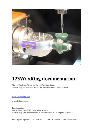
III.2 Machining a wax ring on the 123WaxRingFixture.The result of the Wizard will be a DeskProto screen showing toolpaths for your ring, inthree orientations as defined by the three parts in the tree on the left of the screen.If not already present, load the correct cutter and (re)set the Z 0 position for this cutter.For a Roland machine, make sure that the View button on the machine is not active.On the Roland Control panel check the value for A. This has to be 0.00 degrees. If anyother value is shown, rotate using the A movement buttons until A is zero (the machinedoes not automatically move to A zero as it does for X, Y and Z.Take a wax block of the correct size and place it on the fixture, with the two referencepins in the holes in the wax block. It does not matter which side of the block is up at thispoint. Use the hexagon screw and a washer to fix the wax block (see the illustration).Do not use much force: hand tight is OK.For a Roland machine, in the Tree on the DeskProto screen make the first part (“Part 1:flat”) current by clicking the lamp on it’s line (was off grey, will be on yellow). Younow will see the toolpaths for Part 1. Next in the Create menu choose Extra, and next“Send current toolpaths to machine .”. After a confirmation the machine will startcutting Side 1, as shown in the illustrations
- In the Roland JWX-10 panel (or MDX-40 panel) select "Set the Y-origin at the center of rotation". For further information see the documentation that came with your Roland machine. Setting Z 0: Here as well the standard procedure of the Roland machine may be followed: - Install the sensor on the table and connect the sensor cable to the .