Transcription
Shoal: A Network Architecture for Disaggregated RacksVishal ShrivastavCornell UniversityKi Suh LeeWaltz NetworksAsaf ValadarskyHebrew Universityof JerusalemHan WangBarefoot NetworksAbstractDisaggregated racks comprise dense pools of compute,memory and storage blades, all interconnected through an internal network. However, their density poses a unique challenge for the rack’s network: it needs to connect an orderof magnitude more resource nodes than today’s racks without exceeding the rack’s fixed power budget and withoutcompromising on performance. We present Shoal, a powerefficient yet performant intra-rack network fabric built usingfast circuit switches. Such switches consume less power asthey have no buffers and no packet inspection mechanism,yet can be reconfigured in nanoseconds. Rack nodes transmitaccording to a static schedule such that there is no in-networkcontention without requiring a centralized controller. Shoal’scongestion control leverages the physical fabric to achievefairness and both bounded worst-case network throughputand queuing. We use an FPGA-based prototype, testbed experiments, and simulations to illustrate Shoal’s mechanismsare practical, and can simultaneously achieve high densityand high performance: 71% lower power and comparable orhigher performance than today’s network designs.1IntroductionTraditional datacenter use a server-centric architecture inwhich a number of racks, each comprising tens of serversconnected via a top-of-the-rack (ToR) switch, are interconnected by the datacenter network. However, the endof Dennard’s scaling [18] and the slowdown of Moore’sLaw [14] are challenging the long-term sustainability ofthis architecture [19]. Consequently, a new paradigm hasemerged: rack-scale architecture, where a server is replacedby a rack as the unit of computation, with each rack hosting a number of System-on-Chip (SoC) [15, 35, 65] microservers, each comprising multi-core CPUs integrated withsome local memory, combined with separate pools of nonvolatile memory, storage and custom compute (e.g., GoogleTPUs [82], GPGPUs [74, 78] and FPGAs [43]) blades,all interconnected through an internal network. This enables resource disaggregation as compute units are decoupled from memory and storage units. The benefits disaggregation are well understood in the computer architectureHitesh BallaniMicrosoft ResearchRachit AgarwalCornell UniversityPaolo CostaMicrosoft ResearchHakim WeatherspoonCornell Universitycommunity [5, 41]: it enables fine-grained resource pooling and provisioning, lower power consumption and higherdensity than traditional server-centric architectures, thus enabling each rack to host hundreds of resource “nodes” (compute/memory/storage blades). Several examples of rackscale architecture have been proposed both in industry (Intel [72], Facebook [65, 74], Microsoft [43], SeaMicro [79],HPE [28], Google [82]) and academia [5, 6, 15, 27, 35, 41].Increasing rack density, however, poses new challengesfor the rack’s network. Traditional ToR switches can support only around a hundred ports at high speed. Therefore,interconnecting several hundreds or even a thousand nodesrequires either a high-port count chassis switch or a number of low-port count switches arranged in a hierarchicaltopology, e.g., a folded Clos [1]. Such a design, when coupled with state-of-the-art protocols [2, 4, 20, 25], can providehigh throughput and low latency that could potentially meetthe requirements of disaggregated workloads [19]. Unfortunately, such packet-switched designs are significantly lesspower and cost efficient as compared to today’s intra-racknetworks (§2). Power is a particular concern as the rack’s total power has a hard limit due to cooling [35,60], so networkinefficiency ultimately limits the density of other resources.The limitations of packet-switched networks have alreadyprompted network designs that leverage circuit switches indatacenters [11,23,24,38,42,53]. Such switches can be optical or electrical, and the fact that they operate at the physicallayer with no buffers, no arbitration and no packet inspectionmechanisms means they can be cheaper and more power efficient than an equivalent packet switch (§5). Adopting thesedesigns for intra-rack connectivity would thus alleviate thepower concern. However, achieving low latency would stillbe challenging as traditional circuit switches have reconfiguration delays of the order of few microseconds to even milliseconds. Such a solution, thus, would either compromiseon performance or still have to rely on a separate packetswitched network to handle latency-sensitive traffic. In summary, adapting existing network solutions to high-densityracks would either compromise on power (packet-switched)or on performance (purely circuit-switched).In this paper, we show that it is possible to design a rack-
scale network that operates comfortably within the rack’spower budget while achieving performance comparable topacket-switched networks. Our work is motivated by fastcircuit switches that can be reconfigured in a few to tensof nanoseconds while still being power-efficient. Theseare available commercially [76] as well as research prototypes [10, 16, 17, 30, 35, 36, 48, 52]. Unfortunately, it is notsufficient to simply take existing circuit-switch-based architectures and upgrade their switches as these architectureswere designed under the assumption of slow reconfigurationtimes. In particular, these solutions rely either on a centralized controller to reconfigure the switches [11, 23, 24, 35, 42,53], which would be infeasible at a nanosecond scale, oron a scheduler-less design with a large congestion controlloop [38], which prevents taking advantage of fast reconfiguration speeds.We present Shoal, a power-efficient yet performant network fabric for disaggregated racks built using fast circuitswitches. Shoal reconfigures the fabric using a static schedule that connects each pair of rack node at an equal rate. Thisavoids the need for a centralized scheduler that can operateat a sub-microsecond granularity. To accommodate dynamictraffic patterns atop a static schedule, traffic from each nodeis uniformly distributed across all rack nodes which then forward it to the destination; a form of detour routing. Suchcoordination-free scheduling, first proposed by Chang etal. [9] as an extension of Valiant’s method [50], obviates thecomplexity and latency associated with centralized schedulers while guaranteeing the worst-case network throughputacross any traffic pattern [9]. Such scheduling, however,requires that all nodes are connected through what lookslike a single non-blocking switch. To achieve this, Shoal’sfabric uses many low port-count circuit switches connectedin a Clos topology. When reconfigured synchronously, theswitches operate like a single circuit switch. Further, we decompose the static, equal-rate schedule for the fabric intostatic schedules for the constituent switches.Overall, this paper makes the following contributions: We present a network architecture for disaggregated racksthat couples fast circuit switches with the servers’ networkstack to achieve low and predictable latency at low costand power. We designed a fabric that uses low port-count circuitswitches to offer the abstraction of a rack-wide circuitswitch. We also scaled the coordination-free schedulingtechnique to operate across the fabric. We devised an efficient congestion control mechanism torun atop Shoal’s fabric. This is particularly challenging toachieve due to high multi-pathing—traffic between a pairof nodes is routed through all rack nodes. Shoal leverages the observation that the static schedule creates a periodic connection between any pair of rack nodes to implement an efficient backpressure-based congestion control,amenable to hardware implementation. We implemented Shoal’s NIC and circuit switch on anFPGA; our prototype achieves small reconfiguration delay(6.4 ns) for the circuit switches and is a faithful implementation of our entire design including the scheduling and thecongestion control mechanisms. We incorporated the NIC and the switch prototype intoan end-to-end small-scale rack testbed that comprises sixFPGA-based circuit switches in a leaf-spine topology connecting eight FPGA-based NICs at end hosts.Experiments on this small-scale testbed shows that Shoaloffers high bandwidth and low latency; yet our analysis indicates that its power can be 71% lower than an equivalent packet-switched network. Using a cross-validated simulator, we show that Shoal’s properties hold at scale too.Across datacenter-like workloads, Shoal achieves comparable or higher performance than a packet-switched networkusing state-of-the-art protocols [2,25,54], with improved taillatency (up to 2 lower as compared to NDP [25]). Further, through simulations based on real traces [19], we alsodemonstrate that Shoal can cater to the demands of emergingdisaggregated workloads.2MotivationWe first consider how conventional datacenter networkscould be adapted for disaggregated racks and the shortcomings of such an approach.Strawman 1. Chassis switches with hundreds of ports, often used at higher levels of a datacenter’s network hierarchy,could connect all rack nodes but at significant cost, power,and space. For example, the Cisco Nexus 7700 switch cansupport 768 ports at 10 Gbps (only 192 at 100 Gbps). Yet,it consumes 4 KW power and occupies 26 RU [61], whichis 26% and 54% of the rack’s power and space budget respectively. A rack’s total power has a hard limit of around15 KW due to constraints on power supply density, rackcooling and heat dissipation [35, 60, 66]. We also considered a custom solution involving commodity switches arranged in a Clos topology, which would still consume around8.72 KW to connect 512 nodes (§ 5). The key reason for thisis that packet switching necessitates buffers and arbitrationinside each switch and serialization-deserialization at eachswitch port, which are major contributors (up to 70%) to theswitch’s chip area and package complexity [34, 62], and inturn, its power.Strawman 2. Motivated by the observation that enablinghigh-density racks requires a step change in the powerefficiency of the network, practitioners have attempted tointegrate several very low-port (typically four or six ports)packet switches in the system-on-chip (SoC) of the microserver. Thus, instead of building a ToR-based network,the microservers can be connected to each other using directconnect topologies prevalent in HPC and super-computing
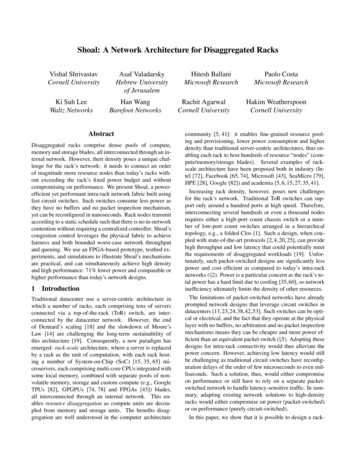
3DesignShoal is a network architecture for disaggregated racks. Itcomprises a network stack at the rack nodes which is tightlycoupled with a circuit-switched physical fabric.3.1Design overviewShoal’s architecture is shown in Fig. 1. Each rack nodeis equipped with a network interface connecting it to theShoal fabric. The fabric comprises a hierarchical collection of smaller circuit switches, electrical or optical, thatare reconfigured synchronously. Hence, the fabric OsRack node12N-1Shoal Fabricsystems, e.g., a 3D torus [41, 68, 79]. This design significantly reduces the overall network power consumption as theadditional logic per SoC is small. However, a key drawbackof direct-connect networks is that they have a static topologywhich cannot be reconfigured based on current traffic pattern. Hence their performance is workload dependent—fordynamically changing workloads such as datacenter workloads, it results in routing traffic across several rack nodes,which hurts network throughput and latency (§7.3) and complicates routing and congestion control [15].Circuit switching. These strawmans lead to the questionwhether packet-switched networks are well-suited to supporthigh-density racks. On the upside, packet-switched networksoffer excellent performance and allow the network core to beloosely coupled with the servers’ network stack. In datacenters and WANs, this has been a good trade-off—the increasedpower of switches is not a key concern yet loose coupling hasallowed the core network technologies to evolve independentof the servers’ network stack. This also allows the networkto be asynchronous, which helps scaling. These benefits,however, do not hold up inside a rack. The physical sizeof a rack means that achieving rack-wide synchronization isfeasible. Further, many density and cost benefits of disaggregated racks come from the co-design of servers and thenetwork, so independent evolution is not critical.Instead, we argue that a circuit-switched network offers adifferent set of trade-offs that are more suited to disaggregated racks. Compared to a packet switch, circuit switchescan draw less power and be cheaper due to their simplicity,and these gains could grow with future optical switches (§5).Thus, they can better accommodate higher density. On theflip side, circuit switching does necessitate a tight couplingwhere all nodes are synchronized and traffic is explicitlyscheduled. Further, past solutions with slow circuit switcheshave had to rely on a separate packet-switched network tosupport low latency workloads which increases complexityand hurts network manageability. Using fast circuit switcheshelps on the performance front yet makes the schedulingharder. We show that these challenges can be solved at thescale of a rack and it is feasible to build a rack network thatsatisfies its power constraints while achieving performanceon par with a packet-switched network.Network FlowShoal Network StackFigure 1: Shoal architecture.like a single, giant circuit switch (§3.2). The use of a circuit switched fabric means that we need to schedule it. Onepossible approach is to schedule it on-demand, i.e., connectnodes depending on the rack’s traffic matrix. However, suchon-demand scheduling requires complicated scheduling algorithms and demand estimation, and would make it hard tomeet low-latency constraints.Instead, Shoal uses coordination-free scheduling [9].Specifically, each circuit switch forwards fixed-sized packetsor “cells” between its ports based on a predefined “schedule”. These per-switch schedules, when taken together, yielda schedule for the fabric which dictates when different nodepairs are connected to each other. The schedule for individual switches is chosen such that the fabric’s schedule provides equal rate connectivity between each pair of nodes. Toaccommodate any traffic pattern atop the equal rate connectivity offered by the fabric, each node spreads its traffic uniformly across all other rack nodes, which then forward it tothe destination (§3.3.1).The second mechanism implemented in Shoal’s networkstack is a congestion control technique that ensures thatnetwork flows converge to their max-min fair rates, whilebounding the maximum queuing at all rack nodes. Ourmain insight here is that the periodic connection of racknodes by the fabric enables backpressure-based congestioncontrol amenable to hardware implementation. One of themain challenges in implementing backpressure-based mechanisms over multi-hop networks is instability for dynamictraffic [26]. In Shoal, we restrict the backpressure mechanism to a single hop, avoiding the instability issue altogether.3.2Shoal fabricShoal uses a predefined, static schedule to reconfigure thefabric such that the rack nodes are connected at an equal rate.Fig. 3 shows an example schedule with N 8 nodes. Thus,in a rack with N nodes, each pair of nodes is directly connected by the fabric once every N 1 time slots, where a slotrefers to the cell transmission time.However, constructing a monolithic switch, electrical oroptical, with hundreds of high-bandwidth ports and fast re-
1b2345678Figure 2: Circuit switches in a twostage Clos topology.12··8123··1234··2Shoal network stackShoal’s mechanisms operate at the data link layer (layer-2)of the network stack. At each node, Shoal spreads its layer-2traffic uniformly across the rack to ensure guaranteed network throughput and implements a congestion control technique that ensures fair bandwidth sharing and low latency.3.3.1Time slot455667····45678··6781··7Figure 3: Fabric schedule for a rackwith 8 nodes.configuration is intractable due to fabrication constraints.Instead, Shoal’s fabric comprises low port-count circuitswitches connected in a non-blocking Clos topology. Arranging k-port circuit switches in a two-stage Clos topology2allows the fabric to connect k2 nodes. For e.g., using 64port electrical circuit switches allows us to connect a rackwith 2,048 nodes. Fig. 2 shows six 4-port circuit switchesarranged in such a topology to implement an 8-port fabric.Packets between any two nodes are always routed throughboth stages of the topology, even if the nodes are connectedto the same switch (like nodes 1 and 2 in the figure). Sincethe topology is non-blocking, this does not impact networkthroughput. It ensures, however, that the distance betweenany two nodes is the same which, in turn, aids rack-widetime synchronization (§3.4).We decompose the schedule of the overall fabric into theschedule for each constituent circuit switch. Consider theexample fabric shown in Fig. 2. Fig. 3 shows the schedulefor this fabric while Fig. 4 shows the schedule for switch1. Each switch’s schedule is contention-free, i.e., at a giveninstant, any port is connected to only one port. This allowsthe switch to do away with any buffers and any mechanismsfor packet inspection or packet arbitration.3.3345··3Forwarding planeRack nodes send and receive fixed-sized cells. Packets received from higher layers are thus fragmented into cells atthe source node and reassembled at the destination. Each cellhas a header (Fig. 5) that contains the corresponding packet’sdestination and other control information.Cells sourced by a node, irrespective of their destination,are sent to the next node the source is connected to. This uniformly spreads traffic across all rack nodes. Each node hasa set of FIFO queues, one for every node in the rack. Cellsarriving at an intermediate node are put into the queue corresponding to their final destination. This ensures traffic is detoured through at most one intermediate node. These queuesare served according to the node’s transmission schedule.We highlight two key aspects of this simple design. First,PortadNodeSwitch 1cabcd1dcba2cdab3dcbaTime slot45cddcabbaFigure 4:Switch 1’s(see Fig. 2 for topology).6cdab7dcbascheduleuniformly distributing traffic is perfectly suited to the equalrate connectivity provided by the Shoal fabric. This guarantees the worst-case throughput across any traffic pattern [9]—Shoal’s network throughput can be at most 2 worse than that achieved by a hypothetical, rack-wide idealpacket switch. To compensate for this throughput reductiondue to detouring, we double the aggregate bisection bandwidth of the fabric for Shoal. This is a good trade-off as circuit switches are expected to be cheaper and hence, addingfabric bandwidth is inexpensive; in §5, the cost of the resulting network is still estimated to be lower than the cost of atraditional packet-switched network.Second, when the fabric’s schedule connects node i to nodej, the former always transmits a cell; the cell at the headof the queue i j is transmitted, otherwise an empty cellis sent. This ensures that each node periodically receives acell from every other node, which enables implementing anefficient backpressure-based congestion control (§3.3.2) andsimple failure detection (§3.5).3.3.2Congestion controlEach node sending traffic computes the appropriate rate forits traffic to avoid congesting the network. We begin with adiscussion of the network topology resulting from periodicreconfiguration of the Shoal fabric and its implications forcongestion control, followed by the details of our design.High Multi-pathing. The periodic reconfiguration ofShoal’s fabric means that the entire network can be seenas an all-to-all mesh with virtual links between each pair ofnodes. For e.g., consider a rack with 8 nodes whose schedule is shown in Fig. 3. Since each node is connected to everynode 1/7th of the time, the network provides the illusion of acomplete mesh with virtual links whose capacity is 1/7th ofeach node’s total network bandwidth.Shoal’s use of detouring means that each node’s trafficis routed through all the rack nodes on their way to theirdestination, resulting in very high multi-pathing. In contrast, the TCP suite of protocols, including protocols tailoredfor datacenters [2, 51] and recent protocols for RDMA networks [39,54] only use a single path. Even multi-path extensions like MPTCP [44] target scenarios with tens of paths,which is an order of magnitude less than the number of pathsused by traffic in our fabric.Design insights. Shoal’s congestion control design is basedon three key insights. First, we leverage the fact that the fab-
ric in an N-node rack directly connects each pair of nodesonce every N 1 time slots. We refer to this interval as anepoch. This means that, when the queues at an intermediatenode grow, it can send a timely backpressure signal to thesender. As we detail below, the periodic nature of this signal coupled with careful design of how a sender reacts to itallows us to bound the queue size across rack nodes.Second, achieving per-flow fairness with backpressuremechanisms is challenging [54], especially in multi-path scenarios. In Shoal, a flow refers to all layer-2 packets beingexchanged between a pair of nodes. For network traffic, thisincludes all transport connections between the nodes. Forstorage traffic, this includes all IO between them. Each flowcomprises N 1 subflows, one corresponding to each intermediate node. Shoal achieves max-min fairness across flowsby leveraging the fact that each flow comprises an equalnumber of subflows that are routed uniformly across a symmetric network topology, so we can achieve per-flow fairnessby ensuring per-subflow fairness. We thus treat each subflowindependently and aim to determine their fair sending rates.The mechanism can also be extended to accomodate otherflow-level sharing policies.Finally, each subflow traverses two virtual links, either ofwhich can be the bottleneck. For e.g., a subflow i j kcan either be bottlenecked at the virtual link between nodesi and j, or between nodes j and k. Shoal maintains a queue,Qi j , at node i to store cells destined to node j. We use thelength of the queue Qi j as an indication of the load on thevirtual link between nodes i and j. Note that the node sourcing the traffic, node i, can observe the size of the local queueQi j . It, however, also needs to obtain information about thesize of the remote queue Q jk that resides at node j.Congestion control mechanism. We use a subflow fromsource i to destination k through intermediate node j, i j k, as a running example to explain Shoal’s congestioncontrol. When node i sends a cell to node j, it records thesubflow that the cell belongs to. Similarly, when node j receives the cell, it records the index k of the queue that the cellis added to. The next time node j is connected to node i, itembeds the current length of queue Q jk into the cell header:rate limit feedback ji len(Q jk )(1)Each pair of nodes in the rack exchange a cell every epoch,even if there is no actual traffic to be sent. Thus, whennode i sends a cell to node j, it gets feedback regardingthe relevant queue at j within the next epoch. Let us assume that node i receives this feedback at time T . At timet ( T ), it knows the instantaneous length of its local queueto node j, Qi j (t), and a sample of the length of the remotequeue between nodes j and k, Q jk (T ). The max-min fairsending rate for a subflow is governed by the most bottlenecked link on its path, i.e., the link with the maximum queuing. As a result, the next cell for this subflow should onlybe sent after both the queues have had time to drain, i.e.,at least, max(len(Qi j (T )), len(Q jk (T ))) epochs have passedsince the feedback was received. To achieve this, node i releases a cell for this subflow into its local queue for j onlywhen the current length of the queue, after accounting for thetime since the last feedback, exceeds the size of the remotequeue Q jk , i.e., a cell is released into Qi j at time t when,len(Qi j (t)) (t T ) len(Q jk (T ))(2)Thus, when a new cell is released into the queue at its source,the previous cell in that queue is guaranteed to have beensent to the remote queue while the previous cell in the remotequeue is guaranteed to have been sent to the destination. Thisensures the invariant that at any given time a subflow has atmost one cell each in both the queue at its source and thequeue at its intermediate node. As a consequence, at anygiven time, the size of each queue Qi j is bounded by:len(Qi j ) outcast degree(i) incast degree( j)(3)Thus, this mechanism ensures that, for each virtual link,Shoal performs fair queuing at cell granularity across all thesubflows sharing that link. This, in turn, results in a tighterdistribution of flow completion times.Note that while Shoal’s basic design assumes a single traffic class for the flows, it can be easily extended to supportmultiple traffic classes as explained in Appendix C.3.3.3Improving network latencyWhile Eq. 3 bounds the queue size, it also highlights one ofthe challenges of detouring: network latency experienced bya cell, while bounded, is impacted by cross-traffic — trafficfrom remote nodes at the cell’s source node and traffic fromlocal node at the cell’s intermediate node. To reduce thisimpact of detouring, we introduce following optimizations:Reducing cell latency at the intermediate node. In addition to queue Q jk , node j also maintains a ready queue R jk .Instead of adding cells to Q jk from local flows that satisfyEq. 2, Shoal adds the corresponding flow ids into the readyqueue R jk . Thus,len(R jk ) outcast degree( j) N 1(4)Shoal then scans the local flow ids in R jk , and adds the corresponding cells into the queue Q jk such that at any given timethere is at most one local cell in Q jk . Thus Eq. 3 changes to:len(Q jk ) 1 incast degree(k) N(5)However, to ensure that the rate limit feedback accounts forthe local subflows, Eq. 1 needs to be updated accordingly:rate limit feedback ji len(Q jk ) len(R jk ) 1(6)The rack network is thus still shared in a max-min fashion,while simultaneously reducing the impact of local traffic onthe latency of remote cells — the latency experienced by aremote cell at any intermediate node is determined only bythe incast degree of cell’s destination.Reducing cell latency at the source node. While Eq. 5 reduces the impact of detouring at the intermediate node, at
the source node i, the latency for a local cell in Qi j is governed by incast degree of intermediate node j. To reducethe impact of cross traffic (i.e., non-local traffic), Shoal selectively adds cells from a new flow to queue Qi j only iflen(Qi j ) 2age , where age is measured in epochs since theflow started. Thus, for the first few epochs, cells will be released to queues over virtual links with low contention, andafterwards will quickly converge to uniform load-balancingusing all virtual links after a max of log(N) epochs. Thisachieves uniform load-balancing for long flows, and hencepreserves Shoal’s throughput bounds, while reducing completion time for short flows.The impact of these optimizations is evaluated in Fig. 14.3.3.4Bounded queuingEq. 5 guarantees that at any given time, the size of eachqueue Qi j at node i is bounded by the instantaneous number of flows destined to destination j plus one, with at mostone cell per flow. This queue bound can be used to determine the maximum buffering needed at each node’s networkinterface to accomodate even the worst-case traffic patternof all-to-one incast. In a rack with 512 nodes and 64 B cells,this requires a total buffering per node of 17 MB. Importantly, since Shoal accesses a queue only once every epochfor transmission, and assuming the access latency of off-chipmemory is less than an epoch, Shoal only needs to buffer onecell from each queue Qi j on the on-chip memory, resultingin N 1 total cells. Using the example above, this leads toon-chip cell buffer size of just 32 KB per node.3.4Shoal slots and guard bandShoal operates in a time-slotted fashion. Slots are separatedby a “guard band” during which the switches are reconfigured. The guard band also accounts for any errors in racksynchronization.Circuit switch reconfiguration. Shoal uses fast reconfigurable circuit switches. For example, our prototype implements an FPGA-based circuit switch that can be reconfigured in 6.4 ns (§4.1). Electrical circuit switches with fastreconfiguration are also commercially available [76] whilefast optical circuit switches with nanosecond-reconfigurationtime have also been demonstrated [12, 16, 17, 30, 36, 48, 52].Time synchronization. Shoal’s slotted operation requiresthat all rack nodes and switches are time synchronized, i.e.,they agree on when a slot begins and ends. Synchronizinglarge networks is hard, primarily because of high propagation delay and the variability in it. In contrast, fine-grainedrack-wide synchronization is tractable due to their size—atypical rack is only a few meters high which means that, evenwhen using optical transmission with a propagation delay of5 ns/m, the maximum propagation latency across a rack isabout 10-15 ns. Furthermore, the rack can be constructedwith tight tolerances to aid synchronization. For example,if all links are the same length with a tolerance of 2 cm,the propagation delay would vary by a maximum of 0.2 ns.Small physical distance also mitigates the impact of temperature variations that could lead to variable propagation delay.Shoal leverages the WhiteRabbit synchronization technique [32, 37, 40, 45] to achieve synchronization with bitlevel precision. WhiteRabbit has b
It comprises a network stack at the rack nodes which is tightly coupled with a circuit-switched physical fabric. 3.1Design overview Shoal's architecture is shown in Fig. 1. Each rack node is equipped with a network interface connecting it to the Shoal fabric.