Transcription
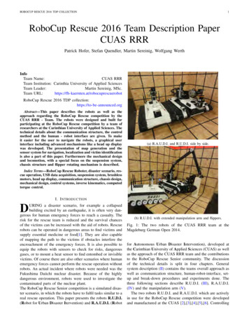
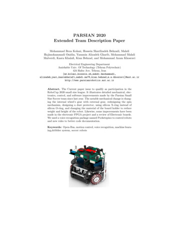
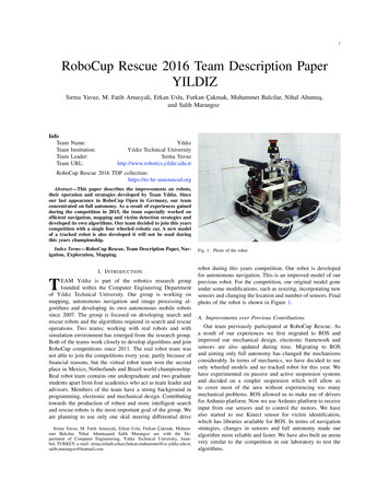
1RoboCup Rescue 2016 Team Description PaperYILDIZSırma Yavuz, M. Fatih Amasyali, Erkan Uslu, Furkan Çakmak, Muhammet Balcılar, Nihal Altuntaş,and Salih r:URL:YıldızYıldız Technical UniversitySırma Yavuzhttp://www.robotics.yildiz.edu.trRoboCup Rescue 2016 TDP his paper describes the improvements on robots,their operation and strategies developed by Team Yıldız. Sinceour last appearance in RoboCup Open in Germany, our teamconcentrated on full autonomy. As a result of experiences gainedduring the competition in 2015, the team especially worked onefficient navigation, mapping and victim detection strategies anddeveloped its own algorithms. Our team decided to join this yearscompetition with a single four wheeled robotic car. A new modelof a tracked robot is also developed it will not be used duringthis years championship.Index Terms—RoboCup Rescue, Team Description Paper, Navigation, Exploration, Mapping.I. I NTRODUCTIONTEAM Yıldız is part of the robotics research groupfounded within the Computer Engineering Departmentof Yıldız Technical University. Our group is working onmapping, autonomous navigation and image processing algorithms and developing its own autonomous mobile robotssince 2007. The group is focused on developing search andrescue robots and the algorithms required in search and rescueoperations. Two teams; working with real robots and withsimulation environment has emerged from the research group.Both of the teams work closely to develop algorithms and joinRoboCup competitions since 2011. The real robot team wasnot able to join the competitions every year, partly because offinancial reasons, but the virtual robot team won the secondplace in Mexico, Netherlands and Brazil world championship.Real robot team contains one undergraduate and two graduatestudents apart from four academics who act as team leader andadvisors. Members of the team have a strong background inprogramming, electronic and mechanical design. Contributingtowards the production of robust and more intelligent searchand rescue robots is the most important goal of the group. Weare planning to use only one skid steering differential driveSırma Yavuz, M. Fatih Amasyalı, Erkan Uslu, Furkan Çakmak, Muhammet Balcılar, Nihal Altuntaşand Salih Marangoz are with the Department of Computer Engineeering, Yıldız Technical University, Istanbul, TURKEY, e-mail: r,salih.marangoz@hotmail.comFig. 1. Photo of the robotrobot during this years competition. Our robot is developedfor autonomous navigation. This is an improved model of ourprevious robot. For the competition, our original model goneunder some modifications; such as resizing, incorporating newsensors and changing the location and number of sensors. Finalphoto of the robot is shown in Figure 1.A. Improvements over Previous ContributionsOur team previously participated at RoboCup Rescue. Asa result of our experiences we first migrated to ROS andimproved our mechanical design, electronic framework andsensors are also updated during time. Migrating to ROSand aiming only full autonomy has changed the mechanismsconsiderably. In terms of mechanics, we have decided to useonly wheeled models and no tracked robot for this year. Wehave experimented on passive and active suspension systemsand decided on a simpler suspension which will allow usto cover most of the area without experiencing too manymechanical problems. ROS allowed us to make use of driversfor Ardunio platform. Now we use Ardunio platform to receiveinput from our sensors and to control the motors. We havealso started to use Kinect sensor for victim identification,which has libraries available for ROS. In terms of navigationstrategies, changes in sensors and full autonomy made ouralgorithm more reliable and faster. We have also built an arenavery similar to the competition in our laboratory to test thealgorithms.
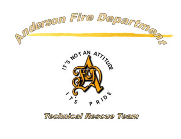
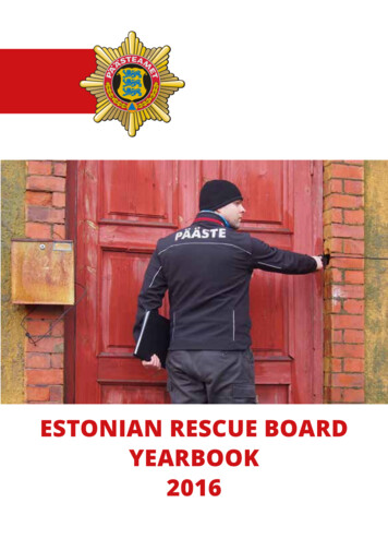
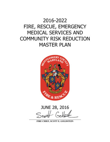
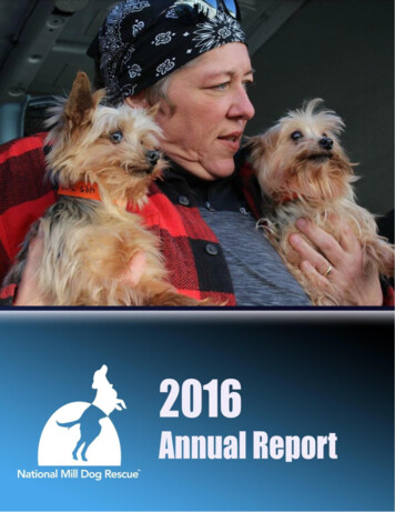
2Fig. 2. The drawings and the picture of the robot platform.II. S YSTEM D ESCRIPTIONOnly one fully autonomous robot will be used per mission.It will try to cover the most of the area using the SLAMand exploration algorithms developed by our team. SLAMalgorithms relying on sensor data and will generate the map ofthe area automatically. Victim detection is planned to be fullyautonomous as well. The robot will only send the necessaryinformation to the operators computer for him to annotate andprint the victim information and the map.A. HardwareAs the robot is skid steering differential drive robot, wholephysical kinematics modeling is hard to reach as the parameters depend heavily on environment variables. Instead kinematics parametrization is achieved according to experimentalkinematics. This way required rotational radius, angular velocities and linear velocities can be realized without deep physicalmodeling.The robot is equipped with different sensors including anRGB-D camera, one LRFs and an inertia measurement unit(IMU) that may be used for exploration and mapping purposes.Additionally, thermal camera, microphone and carbon dioxidesensors are used to detect the victims and to determine theirstates.LRF is the only required sensor to produce 2D map ofthe environment. The inertia measurement unit IMU is alsoutilized to control and stabilize the LRF. LRF is fixed to a baseon top of a pan/tilt unit and the angles of the unit are controlledto be equal to the negative of the angles measured by theIMU. As a result, the LRF direction is stabilized to always belevel and pointing in the same direction. This eliminates therequirement of identifying and removing any noisy or invalidrange scans within the algorithm.Initial drawings of the robot showing the placement of li-pobatteries and the on board computer, are given in 2.Final appearance of the robot is as given in Figure 1.Also important components of the robot and operator stationspecifications are given in Table II and Table I, Appendix C.B. SoftwareAll relevant software packages used by the team is listed inTable III, given in Appendix C.C. Map GenerationSince our last appearance in the competition, we havestarted to use ROS frame-work which allowed us to use variousFig. 3. Sample sensor-based map for the faculty building.tools and libraries. Recently we have developed new R-SLAMMapping software to generate a 2-D map of the environment.We will be using our own navigation software which requiresdata from both victim detection and mapping algorithms.Operator can follow the landmarks and victims found bythe algorithm on the screen. We will extend the software, toprovide an information sheet for each victim found, to allowoperator to edit the victim information. Operator will be ableto print the victim information and the final map using theprint button on the software.We are able to produce reliable sensor-based maps using ourown R-SLAM algorithms, and it is fully adapted into ROS.Sample sensor-based maps generated in our faculty buildingand in laboratory environment, using R-SLAM are given inFigure 3 and Figure 4.Our previous work on SLAM algorithms primarily rely onLRF and encoder data for mapping and localization. Sincethe competition site is more complicated, including ramps,stairs or holes on the walls we are currently incorporating IMUand Kinect data into our software. In our application we aimthe operator to add few annotations to the information sheetprovided by the software and not to interfere with automaticmap generation at all.
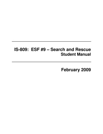
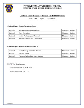
3Fig. 5. The results of the developed system (left) QR-code is marked by bluedot while the hole is pointed out by red one and (right) black/white imageobtained by medianization in the first step of hole detection.Kinect data to head towards the possible victims. Although, the Kinect data is not originally used as a partof the localization software, we intent to use it to correctthe IMU data in future to increase the reliability in realdisaster areas.E. Victim DetectionFig. 4. Sample sensor-based map for the area constructed in the lab.D. Navigation and LocalizationExploration method of the robot is established on frontierbased approach and potential target detection and navigationstudies [1]. Our exploration strategy is based on finding thefrontiers having the greatest potential. Potential frontiers aredefined proximity of the unexplored neighbor grids. Thisdefinition depends on the distance of the paths which iscalculated with A* algorithm between robot and its target.Minimum and optional path is selected and robot is navigatedduring this selected path. Navigation is based on global andlocal planners. Global planner determines the path accordingto Dijkstra algorithm. Local planner uses the dynamic windowapproach [2] [3].Sensors used for navigation and localization are listed asfollows: Inertia Measurement Unit (IMU): It provides 3D orientation, acceleration, 3D rate of turn and 3D earth-magneticfield data.Laser Range Finder (LRF): The field-of-view for thissensor is 240 degrees and the angular resolution is 0.36degrees. It can measure distances up to 30 meters.Ultrasonic Range Finders: Although these sensors arenot crucial for map-ping or localization, they are usedto sense any obstacles close to the ground and are notdetectable by LRF.RGB-D Camera (Kinect): Our navigation algorithm usesMain sensors used for victim detection are as follows;RGB-D Camera (Kinect): We primarily relay on RGB-Ddata to identify any possible victims. While depth informationprovides information to identify possible victims, RGB datais used to confirm the presence of victims. Thermal ArraySensor: Measures the absolute temperature of 8 adjacent pointsin its field-of-view simultaneously. Number of sensors islocated on the robot at different heights. CO2 Sensor: It isused to check the breathing for the victim found. Microphoneand speaker: These are used to detect the sound of the victim.The holes located in different heights on the walls constructing the competition area are possible places for victims.In order to reduce computational load of complex imageprocessing algorithms for victim detection, we first use Kinectdepth data to identify possible victim locations by detectingthe holes. Two steps are used for hole detection. First, a kindof median filter that is developed by our team is appliedto remove noise and convert the greyscale depth data intoblack/white image as seen in Figure 5. At the second step,OpenCV library is used to find segmented hole location.Alongside the hole and depth detection process, RGB images are used to check if there is a victim in the hole. For visualvictim detection, DPM (Deformable Part Models) approach isused [4]. Two of the sample results obtained in our laboratoryis shown in Figure 6.F. CommunicationThere are two access points in our system, one on the robotside and the other on the operator station. These access pointssupport 802.11a/n and 802.11g/n; how-ever we plan to use802.11g/n to communicate between our main robot and theoperator station. The computer used on our robots supports802.11a/n and 802.11g/n will be connected to the access pointvia Ethernet cable. General setup of our system is shown inFigure 7. The wireless communication is between the accesspoints require a selectable 802.11a/n or 802.11g/n band.
4Fig. 8. Operator Interface Initiation.Fig. 6. Victim detection using DPM.Fig. 9. Sensor value tracking.are shared part by part in the diagonal corners and also RGBcamera view and basic robot management command group ispresented. QR code details and retrieval information in QRcodes is extracted and shared in right side of the page.Fig. 7. The general setup of the system.G. Human-Robot InterfaceOnly one fully autonomous robot will be used per mission.It will try to cover the most of the area using the SLAMand exploration algorithms developed by our team. SLAMalgorithms relying on sensor data and will generate the mapof the area automatically. Victim detection is planned tobe fully autonomous as well. The robot will only send thenecessary information to the operators computer for him toannotate and print the victim information and the map. Robotcontrol interface consists of one form with three tab pages,namely Connections, Sensors and Visual Elements. Initiationor connection tab page shown in Figure 8 is divided to twoparts; left side of the page is simulated as an external terminalcapable of executing general Linux or specific ROS queriesand the right side of the page is dedicated to ROS connectionscontaining general startup configuration.Sensors tab page is shown in Figure 9. On the left side ofthis page IMU, Ultra-sonic and Carbon dioxide sensor valuesThe heat map is used to visualize the temperature information which is repre-sented with colors changing between redand white. Thermopile sensor values can be seen on the heatmap as well. Heat map source will be replaced with thermalcamera by the competition. Finally, RGB-depth camera viewand Mapping information are shown in visual elements tabpage shown in Figure 10. Since all algorithms will run onthe robots and only the automatically generated maps andvideo streams will be sent to the operators computer. Usingthe interface, where operator monitors the sensor based mapgenerated by the SLAM algorithm and may eliminate pointshe considered to be faulty, he will also see the position of therobot as calculated by the SLAM algorithm. Mapping visualis generated by computing laser scan data although cameraviews are directly shared using raw camera data which arere-ceived from the network via ROS topics. System history islogged and shared in this tab. Rviz and OpenNI initiation canbe done using application shift buttons. Operator will be usingthis tab to watch the video stream and draw a map. Victimswill be marked here as well.
5the strongest feature of our system is its autonomy. In terms ofmechanical design, we are working on a design that can copewith rough terrain better, besides having financial problemswe will probably need much more work to be successful ona real and completely unknown disaster site.IV. C ONCLUSIONAfter our first competition the main conclusion we drawwas we had to see it to really understand it. It was a greatexperience in many ways: Fig. 10. Visual elements with external video streams. III. A PPLICATIONA. Set-up and Break-DownSince we primarily plan to run for autonomous league, wehave not changed the structure of the operator station toomuch. An aluminum wheeled case will be used to carry allnecessary items for the operator station. The station will bepowered up and powered down with one button. The operationcase contains one laptop, one lcd monitor, one access pointand a power unit. To carry the robot we have another movablechassis with wheels, it is constructed according to the sizeof our robot. Although other team members will assist theoperator to carry the operation case we aim to have only oneoperator to set up and break-down the operator station within10 minutes. Two people will be responsible of carrying therobots inside and outside the competition arena. B. Mission StrategyWe are planning to use only one skid steering differentialdrive robot during this years competition. Our robot is developed for autonomous navigation. Although a new model of atracked robot is also developed it will not be used during thisyears championship. We plan to test our algorithms thoroughlyfor this year and apply them into the new model afterwards.A PPENDIX AT EAM MEMBERS AND T HEIR C ONTRIBUTIONSThe list of the team members and their main responsibilitiesare as follows: C. ExperimentsTo test our robot and algorithms we have built a test area inour laboratuary. To construct standard test methods we haveutilized the ideas dicussed in [5], [6], [7], [8], [9], [10], [11].These tests and validations are also required in our ongoingprojects which are supported by the government agencies andour University. Some details of these experiments are given inprevious sections and in our publications [2]. D. Application in the FieldOn a real disaster site, the main advantage of our systemis being able to move autonomously. Communication wouldarise as an important problem in most disaster sites. If therobot is not able to get back where it has started, the information it gathered inside the ruins becomes completely useless.Although we still have a long way to go in terms of mechanics,We realized that very simple mistakes or not havingenough training time may finish the run at the firstmoment,We had a chance to get to know each other far morebetter under the pressure and tried to establish the teamaccordingly,We realized that we have aimed much more than what wecan achieve for the first time; trying to have different kindof robots caused us not being good enough at anything.For that reason, this time we have decided to concentrateon full autonomy and work on other aspects such asmanipulation in future. Going step by step is proven tobe important.We have had the disadvantage of working on the algorithms up to the last moment and did not run the robotson areas similar to the competition site. As a result, onthe set-up day we realized that our wheeled-robot wastoo close to the ground which prevents it to move evenin a simple ramp. Also for the tracked robot, we onlyrealized an electronic design mistake after burning fewmotor controller cards, when robot got stuck. Now wehave an arena where we constantly try our robots. Sırma YavuzTeam leader, responsible of mechanicaldesign, electronics and SLAM software developmentM. Fatih AmasyaliAdvisor, responsible of victimdetection and image processing software developmentErkan UsluElectronics, controller programmingMuhammet BalcılarSLAM software development,Exploration AlgorithmsFurkan ÇakmakNavigation Algorithm, ROS, ControlalgorithmsNihal AltuntaşImage processing software, victimdetection, 3D mappingSalih MarangozImage processing software, victimdetectionA PPENDIX BCAD D RAWINGSSome drawings of the robot are given in Figure 11.
6TABLE IIIS OFTWARE L BSDOpenCV [12], [13]2.4.8BSDVictim detectionOpenCV [14]2.4.8BSDHazmat detectionSLAM0.1Closed Source2D SLAMProprietary GUI from Yildiz U.0.7Closed Source Operator StationFig. 11. Drawings of the Robot.TABLE IO PERATOR S TATIONAttributeValueNameYildizOpSystem Weight3.5kgWeight including transportation case6.3kgTransportation size0.5 x 0.5 x 0.3 mTypical operation size0.5 x 0.5 x 0.5 mUnpack and assembly time1 minStartup time (off to full operation)1 minPower consumption (idle/ typical/ max)60 / 80 / 90 WBattery endurance (idle/ normal/ heavy load)3 / 1 / 0.5 hCost 3000A PPENDIX CL ISTSA. Systems ListFor the Operator Station, specifications are given in TableI.B. Hardware Components ListMain components of our Robot used by the team is listedin Table II.C. Software ListSoftware packages used by the team is listed in Table III.ACKNOWLEDGMENTThis research has been supported by Turkish Scientific and Technical Research Council (TUBITAK), EEEAG113E212 and Yıldız Technical University Scientific ResearchProjects Coordination Department (Project Numbers: 2015-0401-GEP01 and 2015-04-01-KAP01).TABLE IIH ARWARE C OMPONENT L ISTPartBrand & ModelNum.Robot BaseCustom Made1Electronics for motor control andArduino Uno,2sensor readingsMotor Driver ShieldMotorsMaxon Motor4IMUMicrostrain 3DM-GX21LRF- Laser Range FinderUTM-30LX1Access PointTPLink1Kinect RGB-D CameraMicrosoft Kinect v11ComputerToshiba Sattelite1Thermal CameraOptris Thermal Camera1BatteryLi-Po4Total Price 30000R EFERENCES[1] A. Visser and A. S. Bayu, “Including communication success in the estimation of information gain for multi-robot exploration,” in Proceedingsof the 6th International Symposium on Modeling and Optimization inMobile, Ad Hoc, and Wireless Networks, 2008.[2] E. Uslu, F. Çakmak, M. Balcılar, A. Akıncı, M. F. Amasyali, andS. Yavuz, “Implementation of frontier-based exploration algorithm foran autonomous robot,” in International Symposium on INnovations inIntelligent SysTems and Applications, September 2015.[3] D. Fox, W. Burgard, and S. Thrun, “The dynamic window approachto collision avoidance,” in Proceedings of the IEEE/RSJ InternationalConference on Intelligent Robots and Systems. IEEE, 1996.[4] P. Felzenszwalb, D. McAllester, and D. Ramanan, “A discriminativelytrained, multiscale, deformable part model,” in Computer Vision andPattern Recognition (CVPR). IEEE, 2008.[5] R. Sheh, T. Kimura, E. Mihankhah, J. Pellenz, S. Schwertfeger, andJ. Suthakorn, “The robocuprescue robot league: Guiding robots towardsfieldable capabilities,” in Advanced Robotics and its Social Impacts(ARSO), 2011 IEEE Workshop on. IEEE, 2011, pp. 31–34.[6] S. Kohlbrecher, K. Petersen, G. Steinbauer, J. Maurer, P. Lepej,S. Uran, R. Ventura, C. Dornhege, A. Hertle, R. Sheh, and J. Pellenz,“Community-driven development of standard software modules forsearch and rescue robots,” in Proceedings of the 10th IEEE InternationalSymposium on Safety Security and Rescue Robotics (SSRR 2012), 2012.[7] J. Pellenz and D. Paulus, “Mapping and Map Scoring at theRoboCupRescue Competition,” Quantitative Performance Evaluation ofNavigation Solutions for Mobile Robots (RSS 2008, Workshop CD),2008.[8] R. Sheh, A. Jacoff, A.-M. Virts, T. Kimura, J. Pellenz, S. Schwertfeger,and J. Suthakorn, “Advancing the state of urban search and rescuerobotics through the robocuprescue robot league competition,” 8thInternational Conference on Field and Service Robotics, 2012.[9] A. Jacoff, R. Sheh, A.-M. Virts, T. Kimura, J. Pellenz, S. Schwertfeger,and J. Suthakorn, “Using competitions to advance the developmentof standard test methods for response robots,” in Proceedings of theWorkshop on Performance Metrics for Intelligent Systems. ACM, 2012,pp. 182–189.[10] S. Schwertfeger, A. Jacoff, J. Pellenz, and A. Birk, “Using a fiducial mapmetric for assessing map quality in the context of robocup rescue,” inIEEE International Symposium on Safety, Security, and Rescue Robotics(SSRR). IEEE Press, 2011, pp. 1–6.[11] K. Pathak, A. Birk, S. Schwertfeger, I. Delchev, and S. Markov, “Fullyautonomous operations of a jacobs rugbot in the robocup rescue robotleague 2006,” in International Workshop on Safety, Security, and RescueRobotics (SSRR). IEEE Press, 2007.[12] P. Viola and M. Jones, “Rapid object detection using a boosted cascadeof simple features,” in Computer Vision and Pattern Recognition, 2001.CVPR 2001. Proceedings of the 2001 IEEE Computer Society Conference on, vol. 1, 2001, pp. I–511–I–518 vol.1.[13] R. Lienhart and J. Maydt, “An extended set of haar-like features forrapid object detection,” in Image Processing. 2002. Proceedings. 2002International Conference on, vol. 1, 2002, pp. I–900–I–903 vol.1.[14] S. Liao, X. Zhu, Z. Lei, L. Zhang, and S. Li, “Learning multi-scaleblock local binary patterns for face recognition,” in Advances inBiometrics, ser. Lecture Notes in Computer Science, S.-W. Lee andS. Li, Eds. Springer Berlin Heidelberg, 2007, vol. 4642, pp. 828–837.[Online]. Available: http://dx.doi.org/10.1007/978-3-540-74549-5 87
RoboCup Rescue 2016 TDP collection: https://to-be-announced.org Abstract—This paper describes the improvements on robots, their operation and strategies developed by Team Yıldız. Since our last appearance in RoboCup Open in Germany, our team concentrated on full autonomy. As a result of experiences gained