Transcription
CONFIDENTIALSERVICE MANUALAIRCONDITIONERPlease read this manual carefully before operating your set and retain it for future reference.E-ViewMulti Air ConditionerA4UW30GFH0 [LMU300HHV] / A3UW24GFH0 [LMU240HHV]A2UW18GFH0 [LMU180HHV]Any reproduction, duplication, distribution (including by way of email, facsimile or other electronic means), publication,modification, copying or transmission of this Service Manual is STRICTLY PROHIBITED unless you have obtained the priorwritten consent of the LG Electronics entity from which you received this Service Manual. The material covered by thisprohibition includes, without limitation, any text, graphics or logos in this Service Manual.Copyright 2017 LG Electronics Inc. All rights reserved. Only training and service purposes.P/NO : MFL67452453
1. SpecificationBtu/h ClassBtu/hBtu/hkWkWV, Ø, HzAAAANo. x AWGA2UW18GFH0[LMU180HHV]18,0008400 18000 1998010248 22000 240000.87 1.33 1.921.24 2.20 3.2913.5/2.921.0/10.019.25/9.517.5/9.0208/230, 1, 604.1 6.1 8.75.6 9.8 14.93C x 12A3UW24GFH0[LMU240HHV]24,0008400 24000 3000010248 26000 312000.93 1.78 2.631.25 2.12 3.4713.5/3.621.0/10.719.0/9.8517.0/9.0208/230, 1, 604.2 7.8 11.94.8 9.9 14.93C x 12A4UW30GFH0[LMU300HHV]30,0008400 28400 3408010248 28600 416000.94 2.27 3.471.29 2.32 3.5512.5/3.620.0 / 11.018.75/10.2517.5/9.5208/230, 1, 604.0 10.2 16.74.2 10.9 15.93C x 12No. x AWG---Model NameNominalCapacityPower in Rated MaxMin Rated MaxMin Rated MaxMin Rated MaxNon DuctedNon DuctedMixedDuctedPower SupplyRunning CurrentStarting CurrentWiring ConnectionsCombinationCoolingMin Rated MaxHeatingMin Rated MaxCoolingMaxHeatingMaxPower Supply Cable (Included Earth)Power and Communication CableOutdoor BD Unit(Included Earth)Sum of Indoor Units CapacityMaxNumber of Indoor UnitsMaxNumber of BD UnitsMaxCasing ColorWxHxDWxHxDDimensionsNew WeightCompressorRefrigerantRefrigerant OilHeat ExchangerFanFan MotorSound Pressure LevelSound Power LevelPiping ConnectionsPiping LengthMaximum HeightDifferenceOperation Range(Outdoor Temperature)TypeModelMotor TypeMotor OutputTypePrecharged AmountChargeless-Pipe LengthAdditional Charging VolumecontorlTypeCharged volume(Row x Column x Fins per inch) x No.TypeAir Flow RateTypeOutputCoolingHeatingCoolingLiquidGasTotal PipingMain PipingTotal Branch PipingEach Branch PipingOutdoor Unit Indoor UnitIndoor Unit Indoor UnitBD Unit Indoor UnitCoolingHeatingRatedRatedRatedOuter Dia.Outer Dia.Max.Max.Max.Max.Max.Max.Max.Min. Max.Min. Max.kBth/h243340EA234EAWarm GrayWarm GrayWarm Graymm950 x 834 x 330950 x 834 x 330950 x 834 x 330inch37-13/32 x 32-27/32 x 13 37-13/32 x 32-27/32 x 13 37-13/32 x 32-27/32 x 13kg(lbs)67 (147.7)69 (152.1)69 (152.1)Twin RotaryTwin RotaryTwin RotaryModel x No.GJT325M X 1GJT325M X 1GJT325M X 1BLDCBLDCBLDCW x No.R410AR410AR410Ag (oz)2,800 (98.8)3,200 (112.8)3,200 (112.8)m (ft)15 (49.2)22.5 (73.8)30 (98.4)g/m (oz/ft)20 (0.22)20 (0.22)20 (0.22)Electronic Expansion Valve Electronic Expansion Valve Electronic Expansion ValveFVC68DFVC68DFVC68Dcc x No.950 x 1950 x 1950 x 1(3 x 38 x 16) x 1(3 x 38 x 16) x 1(3 x 38 x 16) x 1PropellerPropellerPropellerm3/min(ft3/min) x No.65 (2,295)65 (2,295)65 (2,295)BLDCBLDCBLDCW x No.124.2 x 1124.2 x 1124.2 x 1dB(A)505252dB(A)545555dB(A)mm(inch)Ø6.35 (1/4)Ø6.35 (1/4)Ø6.35 (1/4)mm(inch)Ø9.52 (3/8)Ø9.52 (3/8)Ø9.52 (3/8)m (ft)50 (164)75 (246.1)75 (246.1)m (ft)m (ft)m (ft)25 (82.0)25 (82.0)25 (82.0)m (ft)15 (49.2)15 (49.2)15 (49.2)m (ft)7.5 (24.6)7.5 (24.6)7.5 (24.6)m (ft) DB( DB)-20(-4)** 48(118)-20(-4)** 48(118)-20(-4)** 48(118) DB( DB)-25 (-13) 24 (75)-25 (-13) 24 (75)-25 (-13) 24 (75)Note:1. All data are based on the following conditions:- Cooling Temperature : Indoor 26.7 C(80 F) DB / 19.4 C(66.9 F) WBOutdoor 35 C(95 F) DB / 23.9 C(75 F) WB- Heating Temperature : Indoor 21.1 C(70 F) DB / 15.6 C(60.1 F) WBOutdoor 8.3 C(46.9 F) DB / 6.1 C(43 F) WB- Piping Length : Interconnected Pipe Length 5 m (16.4 ft)- Difference Limit of Elevation (Outdoor Indoor Unit) is Zero.2. Wiring cable size must comply with the applicable local and national code.3. Due to our policy of innovation some specifications may be changed withoutnotification.4. Sound Level Values are measured at Anechoic chamber.Therefore, these values can be increased(maximum 3dB(A)) owing to ambient conditions during opration.** : The unit could be operated on the followig temperature range only when LowAmbient Kit installed.- Cooling : Outdoor Temperature -20 C(-4 F) -10 C(14 F) DB-2-
2. List of Functions & Accessory2.1 List of FunctionsCategoryReliabilityConvenienceNetwork A2UW18GFH0[LMU180HHV]FunctionsDefrost/DeicingOHigh pressure switchXLow pressure switchXPhase protectionXRestart delay (3-minutes)OSelf diagnosisOSoft startOTest functionXNight Silent OperationOWiring Error CheckOPeak ControlOMode LockOForced Cooling Operation (Outdoor Unit)ONetwork soluation(LGAP)ONote :O : Applied, : Not applied2.2 List of ]A2UW18GFH0[LMU180HHV]DeviceAC Ez (Simple Controller)Central ControllerAC Ez TouchPACEZA000AC Smart IVPACS4B000ACP IVPACP4B000AC Manager IVPACM4B000PI485BNU (Building Network ORKS GatewayPLNWKB000BACnet GatewayPQNFB17C0Y branchXHeader branchXAir GuideXPDI (power distribution indicator)PQNUD1S00ODU Dry ContactXLow Ambient KitO (Logical operation)Note :O : Applied, : Not appliedAccessory model name : Installed at field, ordered and purchased separately by the corresponding model name, supplied with separate package.-3-
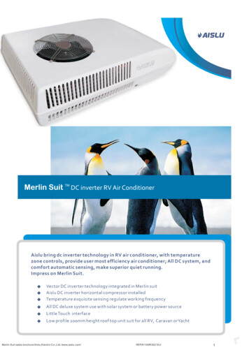
3. Piping Diagrams3.1 30kOutdoor UnitCondenser OutTemperatureThermistorØ 6.35Flare ConnectionInlet istorElectronicExpansionValveROOM AMMain SVC V/VROOM BField PipingLiquid(Ø6.35) ROOM CROOM DPressureSensorMain SVC V/VROOM AROOM BField PipingGas(Ø9.52)ROOM CSuctionTemperatureThermistorROOM DDischargeTemperatureThermistorØ9.52Flare ConnectionAccumulatorInverterCompressor: Cooling: HeatingPCB ConnectorDescriptionCN MID BRCond Middle PipeCN DISCHARGE BKDischarge PipeCN C PIPE VICond Out PipeCN SUCTION GRSuction PipeCN AIR YLAirCN H PRESS RDPressure SensorCN H GAS BKHot Gas ValveCN 4WAY YL4WAY valveCN HEATER BLBase pan heater-4-
3.2 24kOutdoor UnitCondenser OutTemperatureThermistorØ 6.35Flare ConnectionInlet istorElectronicExpansionValveROOM AField PipingLiquid(Ø6.35)MMain SVC V/VROOM BROOM CPressureSensorMain SVC V/VROOM AField PipingGas(Ø9.52)ROOM BROOM hermistorØ9.52Flare ConnectionAccumulatorInverterCompressor: Cooling: HeatingPCB ConnectorDescriptionCN MID BRCond Middle PipeCN DISCHARGE BKDischarge PipeCN C PIPE VICond Out PipeCN SUCTION GRSuction PipeCN AIR YLAirCN H PRESS RDPressure SensorCN H GAS BKHot Gas ValveCN 4WAY YL4WAY valveCN HEATER BLBase pan heater-5-
3.3 18kOutdoor UnitCondenser OutTemperatureThermistorInlet AirTemperatureThermistorØ 6.35Flare cExpansionValveMMain SVC V/VROOM AField PipingLiquid(Ø6.35) ROOM BPressureSensorMain SVC V/VField PipingGas(Ø9.52)ROOM AROOM BØ9.52Flare peratureThermistorAccumulatorInverterCompressor: Cooling: HeatingPCB ConnectorDescriptionCN MID BRCond Middle PipeCN DISCHARGE BKDischarge PipeCN C PIPE VICond Out PipeCN SUCTION GRSuction PipeCN AIR YLAirCN H PRESS RDPressure SensorCN H GAS BKHot Gas ValveCN 4WAY YL4WAY valveCN HEATER BLBase pan heater-6-
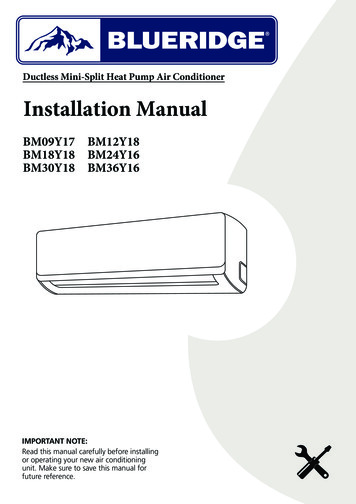
4. Wiring Diagrams4.1 30k-7-
4.2 24k-8-
4.3 18k-9-
INV PCBCN-C HARGECN-H CTOR OUT2REACTOR INREACTOR OUT1CN-HEATER2- 10 -CN-H GASCN-4WAY
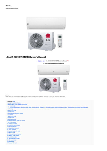
5. Exploded View5.1 3230D 263230B649950263230EW6640A 263230C435301W6640BLocation No.DescriptionSensor InformationHousing Color263230AThermistor(CN DISCHA BK)Discharge PipeBlack263230BThermistor(CN SUCTION GR)Suction PipeGreen263230CThermistor(CN C PIPE VI)Cond Out PipeViolet263230DThermistor(CN MID BR)Cond Middle PipeBrown263230EThermistor(CN AIR YL)AirYellow165000CN H PRESS RDPressure SensorRed- 11 -
5.2 810268711AW4986A268711BW6200263230AW4986B263230D 263230B649950263230EW6640A 263230C435301W6640BLocation No.DescriptionSensor InformationHousing Color263230AThermistor(CN DISCHA BK)Discharge PipeBlack263230BThermistor(CN SUCTION GR)Suction PipeGreen263230CThermistor(CN C PIPE VI)Cond Out PipeViolet263230DThermistor(CN MID BR)Cond Middle PipeBrown263230EThermistor(CN AIR YL)AirYellow165000CN H PRESS RDPressure SensorRed- 12 -
5.3 11AW4986A268711BW6200263230AW4986B263230D 263230B649950263230EW6640A 263230C435301W6640BLocation No.DescriptionSensor InformationHousing Color263230AThermistor(CN DISCHA BK)Discharge PipeBlack263230BThermistor(CN SUCTION GR)Suction PipeGreen263230CThermistor(CN C PIPE VI)Cond Out PipeViolet263230DThermistor(CN MID BR)Cond Middle PipeBrown263230EThermistor(CN AIR YL)AirYellow165000CN H PRESS RDPressure SensorRed- 13 -
Wiring cable size must comply with the applicable local and national code. 3. Due to our policy of innovation some specifications may be changed without . Number of BD Units Max EA - - - Casing Color - Warm Gray Warm Gray Warm Gray . Air Flow Rate m3/min(ft3/min) x No. 65 (2,295) 65 (2,295) 65 (2,295) Fan Motor