Transcription
Downloaded from http://www.everyspec.comAEROSPACE REPORT NO.TOR-2009(8591)-13Space Vehicle Failure Modes, Effects, and Criticality Analysis(FMECA) Guide15 June 2009Roland J. DuphilyAcquisition and Risk Planning OfficeMission Assurance DivisionPrepared for:Space and Missile Systems CenterAir Force Space Command483 N. Aviation Blvd.El Segundo, CA 90245-2808Contract No. FA8802-09-C-0001Authorized by: Space Systems GroupDeveloped in conjunction with Government and Industry contributions as part of theU.S. Space Programs Mission Assurance Improvement workshop.APPROVED FOR PUBLIC RELEASE; DISTRIBUTION UNLIMITED
Downloaded from http://www.everyspec.comAEROSPACE REPORT NO.TOR-2009(8591)-13Space Vehicle Failure Modes, Effects, and Criticality Analysis(FMECA) Guide15 June 2009Roland J. DuphilyAcquisition and Risk Planning OfficeMission Assurance DivisionPrepared for:Space and Missile Systems CenterAir Force Space Command483 N. Aviation Blvd.El Segundo, CA 90245-2808Contract No. FA8802-09-C-0001Authorized by: Space Systems GroupDeveloped in conjunction with Government and Industry contributions as part of theU.S. Space Programs Mission Assurance Improvement workshop.APPROVED FOR PUBLIC RELEASE; DISTRIBUTION UNLIMITED
Downloaded from http://www.everyspec.comAEROSPACE REPORT NO.TOR-2009(8591 )-13Space Vehicle Failure Modes Effects and CriticalityAnalysis (FMECA) GuideApproved by:Michael L. Bolla, Principal DirectorMission Assurance SubdivisionSystems Engineering DivisionEngineering and Technology GroupOffice of Mission Assurance and ProgramExecutionNational Systems GroupSI0290(2, XXXX, 80, KCZ)ii
Downloaded from http://www.everyspec.comAbstractNational Space programs have been surprised late in the life cycle (in I&T or on orbit) with the lateidentification of critical failures, single-point failures, unintended fault effects, and the associatedreductions to system reliability.Consequently, the Mission Assurance Improvement Workshop (MAIW) FMECA Team was establishedto provide detailed guidance to the unmanned, space-vehicle and launch-vehicle industry by preparingthis SV FMECA Guide and presenting it at the Mission Assurance Improvement Workshop on 12–13May 2009. From this point forward, ‘space vehicle’ refers to both space vehicle and launch vehicles.The FMECA team charter was as follows: Identify existing references and assess best practices for FMECA across the domestic andinternational space industry. Establish a current and relevant guidance document explaining thedifferent levels and types of FMECA which can be performed over the life cycle of a NationalSpace Program. Provide recommendations on the scope of FMECA which should be performedas a function of system or product complexity, life cycle phase and space vehicle classes. Focus on FMECA for space vehicle design (exclude manufacturing/I&T process FMECA) Define the interface between FMECA and Fault Managementiii
Downloaded from http://www.everyspec.comAcknowledgementsThis document was created by multiple authors throughout the government and the aerospace industry.For their content contributions, we thank the following contributing authors for making this collaborativeeffort possible:K. Neis—Ball Aerospace and TechnologiesJ. Kawamoto—Northrop Grumman Aerospace SystemsJ. Perazza, LM Fellow—Lockheed Martin Space Systems CompanyF. Groen—NASAJ. Takao—Boeing Space & Intelligence SystemsA special thank you for co-leading this team and efforts to ensure completeness and quality of thisdocument goes to:R. Duphily—The Aerospace CorporationV. Tran—Boeing Space & Intelligence Systemsiv
Downloaded from http://www.everyspec.comContents1.2.Introduction . 11.1Purpose of this Guide . 11.2Background. 31.3Space Vehicle FMECA Guide . 5Ground Work for Successful FMECA . 72.1FMECA requirements/Dialog with Customer . 72.1.1 External Customer (Buyer) . 72.1.23.Internal Customer . 82.2FMECA and Critical Item Control . 82.3FMECA Application: Where and When . 82.3.1ATP to PDR . 92.3.2PDR to CDR . 102.4Understanding the system design, redundancy architecture and SPFs. 112.5Understanding failure mode propagation . 122.5.1Power Interfaces . 132.5.2Thermal Interfaces . 132.5.3Signal Interfaces . 132.5.4Test Equipment Interfaces . 132.5.5HW/SW Interface . 142.6FMECA Planning/Performance Checklist . 142.7FMECA Integration with Fault Management . 14FMECA Types. 173.1Introduction . 173.2Example Subsystem for Evaluation . 173.3Functional FMECA . 183.4Interface FMECA . 193.5Hardware Part-level FMECA . 203.6Final Product Design Failure Modes. 21v
Downloaded from http://www.everyspec.com4.Characteristics of Good FMECA Process and Final Product . 234.1Timeliness . 234.2FMECA Process . 234.3Determine the FMECA Approach . 244.4System Definition . 244.5Functional Block Diagram . 244.6Identify Failure Modes and Effects . 254.7Determine the Failure Mode Effect. 254.8Identify Failure Mode Detection Method. 254.9Provide Failure Mode Compensation Provisions . 254.10Perform Criticality Analysis . 254.11FMECA Documentation . 264.12Single Point Failures (SPFs) . 264.13Critical Items List (CIL). 264.13.1Critical Item Control . 275.Risk and FMECA Type by Space Vehicle Class. 296.Definitions . 337.Abbreviations and Acronyms . 37Appendix A: Annotated FMECA Guide Bibliography . 39Appendix B: Functional/Hardware/Software/Product Failure Modes for Consideration . 43Appendix C: Single Point Failure/FMECA Examples. 58Appendix D: Unit FMECA Example . 63vi
Downloaded from http://www.everyspec.comFiguresFigure 1.Reliability engineering/FMECA process flow. . 2Figure 2.FMECA ATP to launch road map. . 9Figure 3.Component HW FMECA “To Level (extent) Necessary” program decision criteria. . 11Figure 4.Reliability block diagram of deployment subsystem functions. . 17Figure 5.Functional FMECA. . 18Figure 6.Interface FMECA. . 20Figure 7.Hardware FMECA. . 21Figure 8.Sample checklist. 22Fogire 9.Failure Mode Effects and criticality analysis process. . 24Figure C-1. Reliability Block Diagram 1 . 59Figure C-2. TEC Controller Single Point Failure Modes. . 62Figure D-1, Functional block diagrams. . 65Figure D-2. FMECA function sheet. 66TablesTable 1.Severity Categories . 4Table 2.Probability Categories . 4Table 3.Classification Considerations for National Security Space Systems . 31Table 4.Recommended FMECA Type by SV Class . 32vii
Downloaded from http://www.everyspec.com
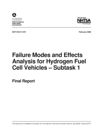
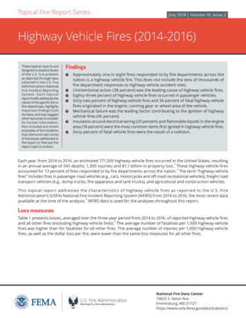
Downloaded from http://www.everyspec.com1. Introduction1.1Purpose of this GuideFailure modes, effects, and criticality analysis (FMECA) is not being used effectively in unmannedspace vehicle (SV) developments as a reliability and systems engineering tool to identify and mitigatedesign, architecture, and fault management risks. As a result, National Space programs have beensurprised late in the life cycle [in integration and test (I&T) or on orbit] with the late identification ofcritical failures, single-point failures, unintended fault effects, and the associated reductions to systemreliability.Consequently, the Mission Assurance Improvement Workshop (MAIW) FMECA Team wasestablished to provide detailed guidance to the unmanned space vehicle and launch vehicle industryby preparing this SV FMECA Guide and presenting it at the Mission Assurance ImprovementWorkshop on 12–13 May 2009. From this point forward, ‘space vehicle’ refers to space vehicle andlaunch vehicles. The FMECA team charter was as follows: Identify existing references and assess best practices for FMECA across the domestic andinternational space industry. Establish a current and relevant guidance document explainingthe different levels and types of FMECA which can be performed over the life cycle of aNational Space Program. Provide recommendations on the scope of FMECA which shouldbe performed as a function of system or product complexity, life-cycle phase, and spacevehicle classes. Focus on FMECA for space vehicle design (exclude manufacturing/I&T process FMECA) Define the interface between FMECA and Fault ManagementThis document applies to the customer program office, contractor program office, and subcontractors.The intended audience for this guide is FMECA planners and performers, namely system/subsystemdesigners, component (black box, instrument, etc.) designers and reliability engineers. This groupforms a critical core team responsible for identifying, eliminating, or mitigating unacceptable failuremodes (those leading to failure of the mission). This guide provides a framework to review thedesign, identify potential failure modes, and assess the effects of the failures. A system-levelassessment is performed to determine if the system is robust to the identified failure modes orrequires remediation. This work is performed iteratively over the program life cycle in a collaborativeeffort between the acquisition team (customer), contractor’s system/subsystem engineering, unitengineering and reliability engineering, teams in an effort to ensure the system design is robust, willmeet customer requirements, and conforms to program-level cost and schedule milestones as shownin Figure 1.1
Downloaded from http://www.everyspec.comFigure 1. Reliability engineering/FMECA process flow.2
Downloaded from http://www.everyspec.com1.2BackgroundThe purpose of FMECAs is to determine, characterize, and document possible failure modes theireffects on mission success through a systematic analysis of the design during initial trades,preliminary design, detailed design, and changes to design after CDR. The analysis is intended toidentify design changes necessary to meet reliability requirements in a timely manner and to fosterinterchange of failure mode information with program activities such as design, system engineering,system safety, integration & test, reliability block diagram development, failure reporting, andcorrective action (FRACAS) and fault management. System safety uses FMECAs to help assesscompliance to fault tolerance requirements for catastrophic failure modes. Design/I&T uses FMECAsduring test failure investigations. Fault management uses FMECAs to design autonomous detectionand protection algorithms to manage specific failure modes. Lastly, on-orbit anomaly analysis teamuses FMECAs to aid in investigations.Historically, many space vehicle programs have used the following (now-cancelled) standards tospecify FMECA requirements: MIL-STD-1543B“Reliability Program Requirements for Space and Launch Vehicles” -Task 204, calls out arange of FMECAs that can be performed MIL-STD-1629“Procedures for Performing a Failure Modes Effects and Criticality Analysis” –Task 101and 102 establishes requirements and procedures for performing a FMECA.Unfortunately, these standards only discuss general requirements for analysis approaches anddocumentation procedures. Many development contractors have developed and use detailed "how-to"FMECA procedures to address these standards for specific product types (e.g., unmanned spacevehicles, unmanned launch vehicles, and ground support equipment). This guide will provide somehow-to guidance for those contractors that have not developed detailed procedures. It will alsoprovide a reference to check for gaps in existing contractor procedures.In practical usage, “FMECA” also means “FMEA” and the distinction between the two has becomeblurred. FMEA C FMECA C Criticality Risk Severity Level/Probability of OccurrenceCriticality is typically qualitative and indicated by the severity level. It can also bequantitative and indicated by the probability of occurrence. Examples are shown in Table1 and Table 2. There are several other ways of determining critically described inAppendix A.3
Downloaded from http://www.everyspec.comTable 1. Severity CategoriesSeverity CategorySeverity LevelCatastrophic Loss of Mission or Life1Degraded Mission2Loss of Redundancy3Negligible4Table 2. Probability CategoriesProbability of Occurrence (PO)LevelProbablePO 0.01Occasional0.0001 PO 0.01Remote0.00001 PO 0.0001Extremely RemotePO 0.00001For some programs, MIL-HDBK-217, Reliability Predictions of Electronic Equipment, failure rateswith detailed probability calculations are used to determine actual failure-mode probability valuesinstead of probability limits or a notional (1, 2, 3, 4) PN scale.On space vehicles, FMECAs are used to help identify and limit critical failures/single point failures,prevent failure mode propagation and identify reliability critical items. For single-point failures thatcannot be designed out or mitigated, critical-item control plans (CICP) are developed and executed tominimize failure mode probability. Presently, FMECA implementation at contractors is varied, andnumerous in-house and commercial tools are available to document FMECA worksheets.The objective of a FMECA is to identify the way failures could occur (failure modes) and theconsequences of the failures modes on space vehicle performance (failure effect) and the severityeffect on mission objectives (criticality). It is usually based on the case upon which failure effects atthe system level are caused by failure modes at lower levels. Criticality is typically a qualitativemeasure (severity) and is normally accompanied by the failure mode’s probability of occurrence forseverity levels 1 and 2.Typical ground rules and responsibilities for a FMECA are established early, along with an overviewof the scope, techniques, design description, step-by-step instructions, sample work sheets, and worksheet data entries. Each program must, of course, add to, delete, and otherwise tailor the procedures toconform to their needs, objectives, and contractual requirements. That is particularly true of safetyissues or workaround operational methods. The most effective FMECA processes have either standalone FMECA plans or are included as sections of reliability program plans, product assurance plans,or mission assurance plans. Typical FMECA plans should include: The FMECA team players (reliability, design, system engineering, subsystemengineering, system safety, subcontractors, etc.)Schedule of activities.System information: functional block diagrams, schematics, typical failure modes,interface control documents, etc.Description of the final FMECA report (see Section 4.2.8).4
Downloaded from http://www.everyspec.com1.3Space Vehicle FMECA GuideThis SV FMECA Guide provides guidance to the space vehicle developer on how to plan andimplement a detailed how-to FMECA process for unmanned space vehicles and electrical groundsupport equipment (EGSE)/mechanical ground support equipment (MGSE) which interfaces with theSV. Elements of the guide address how FMECAs are used by fault management system designers.The FMECA guide also addresses one of the elements of an effective design assurance process. Theprocess begins during the proposal with dialogs with the customer, the development of an explicitFMECA plan, clear ground rules, roles, contractor/subcontractor responsibilities and FMECAdocumentation requirements. The breadth, depth, and formality of the FMECA process is a functionof the specific mission under development and is dictated by factors such as mission class (A, B, C,D), allowable risk level (low, medium, high), and available resources specified by the customer.This guide focuses primarily on hardware equipment failure modes. A more detailed discussion onequivalent software FMECAs will be included in a future version of this document.The program manager or designee (system engineering) must ensure that the proper guidelines existfor use by the development team in the identification of potential failures that are not an acceptablerisk to the mission and must therefore be resolved. Depending on applicable risk managementpolicies, such determinations may involve the quantification of failure likelihoods by reliabilitymodels. A FMECA roadmap and training plan should be developed and communicated to theFMECA team (system/subsystem engineers, fault management, component designers, reliabilityengineers, system safety and subcontractors). Contractor management and/or the customer shall havefinal approval on accepting for flight, any mission critical failure mode that may affect systemperformance and jeopardize mission objectives.Strategic decisions to be made by management:1. What types of FMECAs will be done? (functional, hardware, interface, etc.)2. What selection criteria will be used to identify new FMECAs? (new designs, new manufacturingprocesses, etc.)3. What is appropriate FMECA timing? (ATP-PDR, PDR-CDR, CDR-Launch)4. What FMECA standard will be used? (Appendix A item, Internal command media, etc.)5. What generic FMECAs will be developed? By whom?6. What program-specific FMECAs will be developed? By whom?7. What level of detail is needed for generic or program-specific FMECAs? (system, subsystem,component, piece part, etc.)8. Will FMECA quality surveys be used to gauge FMECA effectiveness? If so, how will this bedone?9. How will FMECA projects be tracked?10. How will FMECA post-analysis lessons learned be captured?11. How will FMECAs be archived for easy retrieval?12. What linkages are needed to other processes (design reviews, configuration control boards,FRACAS, design assurance, fault management, etc.)13. How will supplier FMECAs be specified in the supplier statements of work (SOWs) be handled?Who will review and approve supplier FMECAs for critical equipment?14. How will design changes after CDR or unanticipated failure modes identified during I&T behandled?5
Downloaded from http://www.everyspec.comAs soon as functional block diagrams become available, a FMECA team of designers and reliabilityengineers review the design to identify plausible/realistic failure modes that would affect system(s)performance, cause personnel injury, and cause hardware damage. Appendix B provides a partial listof failure modes for consideration by the integrated product team. Preliminary results andrecommended improvements support trade studies and preliminary design review (PDR). As detailedinformation becomes available, hardware, hardware/software interaction, and electrical/mechanicalinterface failure modes are evaluated and documented in an FMECA report that is summarized atcritical design review (CDR). Of special importance are electrical/mechanical interfaces for SV/LV,SV/GSE (power) and bus/payload. As the design changes due to failures during integration and test,the FMECA is updated as necessary to reflect the as-built space vehicle.It is essential that a closed loop system of checks and balances, such as change control boards (CCB),be employed to ensure that all resulting design changes are reflected into the design and FMECAs asappropriate. Extreme care must be exercised in the implementation of design changes to overcome thepotential effects of a problem to ensure that overall mission and system(s) reliability is not, in fact,degraded. As design changes are instituted at any hierarchical level for any reason, that portion of theanalysis must be repeated and the results incorporated back up the mission hierarchical line asnecessary to determine the effect on system(s) performance and mission success.The FMECA process is intensely iterative, interactive, and an integral and inherent part of the overalldesign process. These facts dictate that the FMECA process can only be effectively and efficientlyaccomplished in a timely fashion by the FMECA lead with cognizant, responsible, and accountabledesign engineers at each of the various mission hierarchical levels. Members of the flight operationsteam should join with the flight system design team as part of the process.6
Downloaded from http://www.everyspec.com2. Ground Work for Successful FMECA2.1FMECA requirements / Dialog with CustomerToday’s commercial, civil, and military space vehicles are highly complex, integrated systemscomposed of mechanical, electronic, electrical, and electromechanical hardware (HW) and software(SW). These systems are supplied by a prime contractor and integrated product teams (IPTs),composed of in-house product centers, and multiple subcontractors. External customers can bedomestic or international and expect that the prime contractor will meet mission requirements andensure mission success given the limited resources that are committed by contract. The primecontractor, IPTs, and internal program offices implement a systems engineering process to design,manufacture, integrate, and test all HW and SW. Reliability engineering conducts FMECAs toidentify and limit single-point failure modes and prevent failure mode propagation as part of asystems specialty engineering IPT. Typically, FMECAs are performed at the system, subsystem,assembly, and component level and become detailed, as necessary, to ensure adequate redundancy,mission reliability, availability, safety, telemetry, design life, mission life, mean mission duration(MMD) and fault isolation/recovery by autonomous and ground based means.2.1.1External Customer (Buyer)The purpose and scope of FMECAs are often a hotly debated topic due to the amount of resourcesconsumed. External customer FMECA needs are normally identified early-on as a SOW, reliabilityrequirement and a preferred FMECA standard process within a competitive or sole source request forproposal (RFP), with the intent to ensure mission success. In a conservative sense, the externalcustomer endeavors to identify all failure mode risks from the top-level system down to the piece-partlevel. On the other hand, the prime contractor, IPT, and internal program offices have limitedresources and aspire to only conduct FMECA to the level necessary within the confines of theircommand media. External customer SOWs define the purpose and scope of the FMECA by callingout “tailored” military standards such as MIL-STD-1543B “Reliability program requirements forSpace and Launch Vehicles” for space applications, and MIL-STD-785 Reliability Program forSystems and Equipment Development and Production” for non-space applications. Externalcustomers typically call out MIL-STD-1629 “Procedures for Performing a FMECA” to provide abasis for a FMECA’s minimum content. Implementation of externally, customer-tailored militarystandards is controlled, clarified, and agreed to by the external customer, the prime contractor, andIPTs by a Reliability Program Plan (RPP). The RPP is preferably approved before contract awardand many times after contract award as the program office builds/matures. It is at this juncture thatthe external customer and the program office need to agree and nail down the purpose and scope ofthe FMECA. This agreement provides for a smooth FMECA implementation, such that the primecontractor and IPTs know exactly what is required. Failure to adequately define and tailor the scopeof the system, subsystem, assembly, and component FMECA early on promotes schedule delays, costgrowth, and threatens mission success.The minimum FMECA tailoring promoted by this guide is system-level functional and interfaceFMECAs; Subsystem level functional and interface FMECAs; Assembly-level-functional andinterface FMECAs; and component-functional, interface, and hardware FMECAs (to the levelnecessary). It is noted that the interface FMECAs examine relevant component internal-interfacepiece parts and external interfaces between components. The FMECA tailoring is communicated to7
Downloaded from http://www.everyspec.comin-house IPTs by the RPP and suppliers by the subcontract SOW, RPP, and the contract datarequirements list (CDRL).2.1.2Internal CustomerThe internal customer is the prime contractor’s program office, who is engaged in the overall contractwith the external customer. The internal customer establishes integrated product teams (IPTs) forsubcontracted and in-house product
Air Force Space Command 483 N. Aviation Blvd. El Segundo, CA 90245-2808 . developments as a reliability and systems engineering tool to identify and mitigate design, architecture, and fault management risks. As a result, National Space programs have been . "Reliability Program Requirements for Space and Launch Vehicles" -Task 204, calls .