Transcription
International Journal of Engineering Research & Technology (IJERT)ISSN: 2278-0181Published by :http://www.ijert.orgVol. 5 Issue 04, April-2016Design Failure Modes and Effects Analysis(DFMEA) of a Human Powered RecumbentVehicleManish BeheraBaishakhi BeheraB. Tech,Department of Mechanical EngineeringCollege of Engineering & Technology, Bhubaneswar,IndiaB. Tech,Department of Mechanical EngineeringCollege of Engineering & Technology,Bhubaneswar, IndiaAbstract - American Society of Mechanical Engineering(ASME) organizes International Human Powered VehicleChallenge (HPVC) to provide a technical platform to buddingtechnocrats to manifest the application of sound engineeringdesign principles. This competition aims at “development ofsustainable and practical transportation alternatives” [6]. InHPVC, students team up to engineer a highly efficient vehiclewhich can be utilized in our everyday use- from commuting towork, to carrying goods to market. A recumbent vehicle is atwo/ three wheeler which places the rider in a laid-backreclining position. These vehicles are abundantly in use inWest. They have wide applications-as means oftransportation, recreation, exercise and as a freight vehicle.These vehicles are human powered and makes no use of fuel.Thus, they are eco-friendly in nature. In ASME HPVC,recumbents are designed and fabricated indigenously by thestudents. The recumbents in ASME HPVC are slightlymodified to have fairings so as to have an increased speed forracing purpose. Given the non uniform roads that the vehiclewill be subjected to especially in India, it is quite important tohave a safe and strong design of the vehicle. Thus, the possiblecritical failure points and its mode of failure needs to beidentified in the design stage itself and preventive measures betaken. An effective tool for making a failure analysis isDFMEA (Design Failure Modes and Effects Analysis) which isan augmentation of widely used Failure Modes and EffectsAnalysis (FMEA) technique. This analysis is done in thedesign stage. DFMEA has been used to predict and analyzevarious failure modes of a recumbent vehicle, its cause &effects and to outline preventive measures. Risk PriorityNumber (RPN) methodology is used to identify the criticalparts which are more vulnerable to failure and needs extraattention.Keywords: Recumbent Vehicle, ASME HPVC, HumanPowered, Design Failure Modes and Effects Analysis (DFMEA),Risk Priority Number (RPN), RPN graph1. INTRODUCTIONWorld Human Powered Vehicle Association definesHuman Powered Recumbent Vehicle as “a vehicle with aseat position that is inclined backwards and the bottombracket and the pedals are attached front” [8].Thesevehicles are driven by muscular strength. The vehicle’sapplication areas are- commuting of passengers,transportation of goods, means of exercise, means oftransport in rough terrain, inaccessible areas and to help inrelief tasks in emergency situations like drought, floods etc.The Human Powered Vehicle Challenge organized byASME aims at development of vehicles with such servicepotentials as well as being eco-friendly. The competitioninvolves design, fabrication and on ground races. Thedesign and the fabrication are entirely done by the students.Given the rigors of the terrain, human force and freightloading that the vehicle will be subjected to, a safe and anefficient design is of utmost importance for successfuloperation of the vehicle. This includes identification ofpotential failure points, modes of failure, cause and effectof the failure and taking required preventive measure at anearly design stage.The Failure Modes and Effects Analysis (FMEA)technique of failure analysis is the apt tool for the aboveproject. As defined by American Society of Quality (ASQ),“Failure modes and effects analysis (FMEA) is a step-bystep approach for identifying all possible failures in adesign, a manufacturing or assembly process, or a productor service.” [3]. For failure analysis in design stage, DesignFailure Modes and Effects Analysis (DFMEA)methodology of FMEA is used. Thus, DFMEA is appliedon the project and failure analysis is made. Risk PriorityNumber (RPN) is used to have a numerical analysis of thepotential failure modes and based on this number thesensitive parts of the vehicle are identified and preventivemeasures are taken. The main design aspects of therecumbent vehicle consists of the Frame, Roll overProtection System (RPS), Tie rod, Suspension, Storageframe and Steering column.2. FAILURE MODES AND EFFECTS ANALYSISOtherwise known as Failure Modes, Effects and CriticalityAnalysis (FMECA), it is a methodic, well ordered andthorough going analysis of various failure modes, theircauses and effects. It leads to identification of the criticalcomponents of the subject under study to facilitateimplementation of preventive measure.The application of FMEA dates back to 1949 whenprocedures for conducting FMECA were described in USArmed Forces Military Procedures document MIL-P-1629.27IJERTV5IS040105(This work is licensed under a Creative Commons Attribution 4.0 International License.)
International Journal of Engineering Research & Technology (IJERT)ISSN: 2278-0181Published by :http://www.ijert.orgVol. 5 Issue 04, April-2016Table 1: Severity Assessment and Rating CriteriaWith the onset of 1970s, FMEA became widely used inautomotive sector as well as in space projects. NASAprograms using FMEA variants included Apollo, Viking,RPN is the product of numerical markings of Severity offailure, Likelihood of occurrence of failure and Likelihoodof detection of failure. Equations (1) and (2) shows theformula for calculating RPN and Total RPN-Voyager, Magellan, Galileo and Skylab while inautomotive sector; it finds its use in Ford Motor Companyand Toyota. At present FMEA is popular in other sectorslike semiconductor processing, food service, plastics,software, and healthcare.RPN (SEVERITY MARKING)*(LIKELIHOOD OFOCCURRENCE MARKING)*(LIKELIHOOD OFDETECTION MARKING)(1)TOTAL RPN SUM OF ALL RPNsFMEA can be categorized into 3 types as in System,Design and Process FMEA [4]. Of the three, Design FMEAor DFMEA is used to analyze designs before the design isgiven to start production.After this, the components/parts were arranged indecreasing order of their RPN. Graph was plotted to get acomparative view of the most critical parts/components.The components/parts with highest RPN is given mostimportance during fabrication followed by componentswith next higher RPNs. The main objective is to have areduced Total RPN [refer (2)] as this would ensure safedesign of the recumbent vehicle.Risk Priority Number is a numerical based analysis ofcomponents based on their sensitivity to failure. Thisnumber helps in spotting the more critical components andthus helps in making the design sturdy as the “dangerspots” are given extra attention during fabrication.4. SEVERITY, LIKELIHOOD OF OCCURRENCE,LIKELIHOOD OF DETECTIONSeverity (S) refers to the degree to which harm will takeplace if a failure mode occurs. It is marked from 1 to 10. 1represents “harm with less or zero severity” while 10represents “harm with maximum severity”.Likelihood of Occurrence (O) refers to the possibility of anoccurrence of a failure mode. It is also scored from 1 to 10.1 suggests “unlikely to occur” while 10 suggests “mostlikely to occur”.Likelihood of Detection refers to the likeliness of detectionof failure if the failure mode occurs. It is too rated from 1to 10.1 stands for “very likely to be detected” while 10stands for “very unlikely to be detected”. The tables 1, 2and 3 illustrate the details.For having the best design, DFMEA along with RPNmethodology has been implemented in the project ASMEHPVC.3. DFMEA AND RPN METHODOLOGYThe various parts of the recumbent trike were outlined. Foreach part, failure modes and its causes & effects weredetermined. Next, Severity of the failure, Likelihood ofoccurrence of failure and Likelihood of detection of thefailure were determined for each failure mode. All theseparameters were assessed and marked from 1 to 10. Detailsof these parameter ratings are discussed in the next section.Finally, RPN of each failure mode was calculated.SL.No.1.SEVERITY’ DENOMINATION(2)SEVERITY RATINGDESCRIPTIONHazardous with Maximum Severity and occurswithout warning102.Very Hazardous and occurs with warning9Failure occurs without any prior effects. Vehicle’s coredesign is compromised. Rider’s safety is at stake. Vehiclemay be inoperable. Vehicle may be dismantled wholly.Occurs due to poor fabrication, non compliance withstandardand regulations,Failure isruleslife risking.It occursaccidents.with a warning. Occurs dueto negligence in periodic repair work, poor fabrication, andlow quality raw materials. Vehicle needs to be abandoned.3.Very High84.High75.Moderate66.Low57.Very Low48.Minor3Ergonomically poor. Repair is needed.9.Very Minor2Vehicle is functional. Performance slightly below optimumlevel. Not a concern.10.None1No striking effect, with the vehicle performanceremaining unaffected.Vehicle is inoperable. Immediate overhauling is therequirement. Occurs due to accidents, usage of nonstandardized parts, workforce inefficiency, and noncorporation of vehicle safety standards.Vehicle’s performance is compromised greatly. ExtensiveRepair work is necessary.Vehicle is operable. Comfort and aesthetics arecompromised. Performance loss takes place. Repair cando the job.Vehicle is functional. Audible noises are heard. Minorvibrations are there. Repair work is enough with noreplacements necessary.Failures due to aligning, fitting, finishing problems. Pettywear and tear occurrence. Can be overcome by re-work ofthe vehicle.28IJERTV5IS040105(This work is licensed under a Creative Commons Attribution 4.0 International License.)
International Journal of Engineering Research & Technology (IJERT)ISSN: 2278-0181Published by :http://www.ijert.orgVol. 5 Issue 04, April-2016Table-2: Likelihood of Occurrence Assessment and Rating CriteriaSl.No.1.LIKELIHOOD OF OCCURRENCE’ DENOMINATIONExtremely High: Failure is unavoidable and perpetual10Failure in every fourth component (1:4)2.High9Failure in every sixth component (1:6)3.High: repeated failures8Failure in every tenth component (1:10)4.High: frequent failures7Failure in every 50 component (1:50)5.Moderately High: Frequent failures6Failure in every 200 component (1:200)6.Moderate: Occasional failures5Failure in every 600 component (1:600)7.Moderately Low: infrequent failures4Failure in every 5000 component (1:5000)8.Low: Few failures39.Very Low: Isolated failures210.Remote: Failure unlikely1Failure inevery 500000 component(1:50000)Failure inevery200000component (1:200000)Failure in every 3 million component(1:3million)RATINGDEFINITIONTable-3: Likelihood of Detection Assessment and Rating CriteriaSl. No.1.DETECTION’ DENOMINATIONImpossible to detectRATING102.Very Remote9DEFINITIONAlmost negligible chances of the failure mode gettingdetectedVery slight chance of detection of failure mode3.Remote8Far off chance of detection of failure mode4.Very Low7Minimal chance of failure mode detection5.6.LowModerate65Failure mode may be detectedModerate chance of detection of failure7.Moderately High4Fair likelihood of detection of failure mode8.High3Failure mode detection is high9.Very High2Higher possibility of failure mode getting detected10.Certain1Certain detection of failure by controls5. DFMEA IMPLEMENTATIONThe DFMEA was applied on different components of theHuman Powered Recumbent Vehicle. Analysis was madeon 15 components of the recumbent vehicle namely Frame,Handlebar, Tires, Rims, Cassette, Bottom Bracket, Seat,Storage space, Tie rod, Steering column, Knuckles,Suspension, Fairing, Braking system and Electricalcomponents. The detailed analysis using DFMEA isillustrated in table4.29IJERTV5IS040105(This work is licensed under a Creative Commons Attribution 4.0 International License.)
International Journal of Engineering Research & Technology (IJERT)ISSN: 2278-0181Published by :http://www.ijert.orgVol. 5 Issue 04, April-2016Table-4: DFMEA WORKTABLESlNo.COMPONENT FAILURE D*RPN*58400Selection of correctmaterial having high yieldstress, Considering highfactor of safety in designstage, Careful testing andanalysis, efficient welding3372Choosing of a materialwith high factor of safety5525037147Choose materials withhigh FOS;Highly efficient designandlubrication,testingProper1.FrameTorsion, Bending,Rolling, Cracks,Broken welds,Structural forcesAxial stress, Impactloading, Fatiguestress, FabricationDefectsBending and weakening offrame, Damage to Roll overprotection system, Allmounting parts getsweakened, Rider’s safety iscompromised2.BottomBracketAxial loads,Bending, TorsionExcessive bearingand bending stressBreak in connection of crankwith the vehicle,Transmission breakdown3.HandlebarBending failure,Structural failureExcess of impactloading4.Cassette &Crank setTorsion failure,Fatigue failure,MechanicalfailureExcessive wear andtear, accidentsGear shifting failure,Performance compromised7Storage SpaceImpact Failure,Bearing failureOverloading, Shockloads, Frame faultsStorage space gets damaged46124The supporting frameshould a material of highfactor of safety, Loadingbeyond a permissiblerange should be preventedBending failure,Torsion failure,BucklingMechanicalfailure, CyclicfailureRough terrain travel,OverloadingSteering Mechanism fails,Rider’s safety is compromised944144Rough Terrain,excessive loadingduring steering,loosening of boltsSteering failure, Severevibrations, Rider’s safety iscompromised, Vehicleperformance is affected953135Extensive structuraltesting, proper materialselection and designPeriodic fitting and repairwork, Selection of amaterial with a high factorof safetySpring failures,MechanicalfailuresInappropriate choiceof springsRider’s comfort as well asvehicle parts are compromised4128Selection of a standardsuspension system758280Proper selection ofmaterial with high factorof safety4280Periodic checking andreplacement5.Vehicle Imbalance, Rider’sSafety is compromised6.SteeringColumn7.Tie Rod11.Suspension12.KnucklesStructural failure,MechanicalfailureExcessive bending,crushing stressVehicle performance iscompromised, lesser comfort10.Mechanicalfailure, Heatfailure, WearingSidewall failure,Tread separation,Bead failureExcessive wear andtear, snapping ofbrake wire,Improper mounting,excessive pressurepuncture, Excesson padsinflationPoor braking11.BrakingSystemTires12.RimBrittle or DuctileFracture, Frettingfatigue, Cyclictorsion13.Rider seat14.15.10810Periodical checkups andreplacements, use ofstandard cassette10Vehicle becomes inoperable873118Careful mounting,material testing andanalysis, proper inflatingprocess, regular check upOn road damage,large radial andtangential stresses,Faulty mountingVehicle becomes inoperable936162Using standard rims,Proper Suspension systemFrame failure,Misalignment,fitting problemExcess load causingbearing stress,Stressconcentrations,Improper fitting tothe frameRider’s safety & comfort arecompromised, Ergonomicallypoor93127Selection of propermaterial with requiredcritical bearing stress,proper fitting andapplying cushionFairingProjectilepenetration, Tear,Mounting failureCollision of aforeign object, Highvelocity wind flow,Head on collisionAesthetically poor, Reductionin optimal speed, Racingpotential hampered35115Selection of a materialwith high factor of safety,fairing mountings shouldbe strongVehicleElectricalcomponentsOpen circuit,Electrical short,connectionStrippingWater entry,Incorrectconnection,Electrical FailureComponent becomes nonfunctional44116Proper insulation, This work is licensed under a Creative Commons Attribution 4.0 International License.)
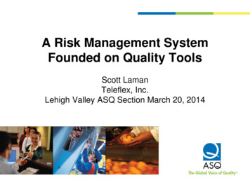
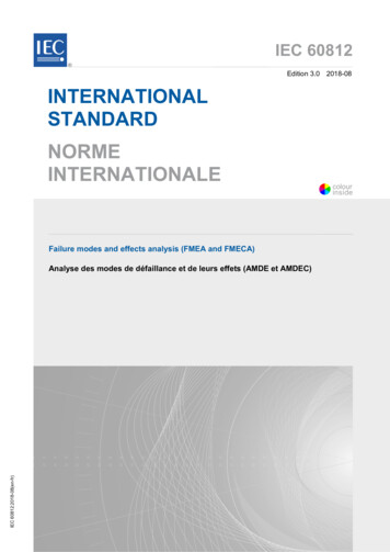
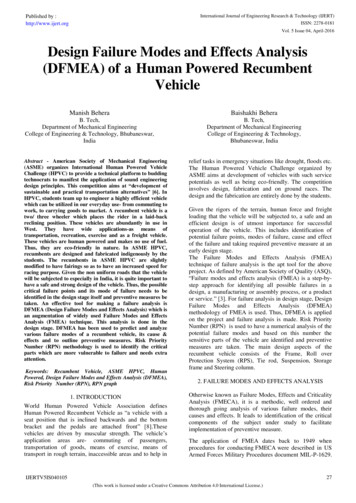
International Journal of Engineering Research & Technology (IJERT)ISSN: 2278-0181Published by :http://www.ijert.orgVol. 5 Issue 04, April-20166. PRIORITY GRAPHPriority Graph is a graphical representation of RPNs of thecomponents. After the above analysis, the priority graphwas plotted with RPN in y-axis and Components in x-axis.The graph gives a comprehensive view of the components400350300250200150100500with greater RPNs. Thus, extra care and recommendedpreventive measures will be taken for such criticalcomponents. Fig.1. shows the priority 1. RPN Graph7. DFMEA ASSESMENTA full-fledged DFMEA was carried out on the HumanPowered Recumbent Vehicle. The analysis brought forththe fact that the Frame, Handlebar, Knuckle, Rim, Cassette& Crank set and Steering Column are the criticalcomponents with high RPN which require first handattention and top notch design and testing.8. CONCLUSIONThe DFMEA was targetfully applied on thecomponents of the Human Powered RecumbentVehicles. The various analysis aspects as in Severity,Likelihood of Occurrence and Likelihood ofDetection were clearly outlined and defined. Based onthese aspects, a rating based analysis was done. RPNwas calculated for each. The analysis was plotted on agraph to spot the critical components. Requiredpreventive measures were recommended. Thesefindings were incorporated during the design andfabrication of our own Human Powered RecumbentVehicle. Fig. 2 shows the picture of our recumbentvehicle.Fig.2.Human Powered Recumbent Vehicle31IJERTV5IS040105(This work is licensed under a Creative Commons Attribution 4.0 International License.)
International Journal of Engineering Research & Technology (IJERT)ISSN: 2278-0181Published by :http://www.ijert.orgVol. 5 Issue 04, April-2016REFERENCES[1] Nancy R. Tague. “The Quality Toolbox”; Second Edition;ASQ Quality Press, 2004[2] Collins A. Jack, Busby Henry, Staab George. “MechanicalDesign of Machine Elements and Machines: A FailurePrevention Perspective”; Second Edition[3] American Society of Quality (ASQ), Failure Modes andEffects Analysis (FMEA); -tools/overview/fmea.html[4] 4. Six Sigma Green Belt Training Material, ICSL VSkills, p22, 23, 24, 147; www.vskills.in[5] Suresh. R, Sathyanathan. M, Visagavel. K, Kumar Rajesh.M. “Risk Assessment for Blast Furnace using FMEA”;International Journal of Research in Engineering andTechnology[6] ASMEHPVCINDIA2016RULES;http://www.hpvcindia.in/[7] -(hpvc)[8] va.org/[9] MEA&Reliability.pdf[10] http://www.ijera.com/papers/Vol3 issue2/BA32348350.pdfBIOGRAPHYManish Behera is currently pursuing B.Tech Degree inMechanical Engineering from College of Engineering andTechnology (BPUT), Bhubaneswar, Odisha, India. He iscurrently the member of American Society of MechanicalEngineering (ASME). He is serving as the Head ofOperations of ASME CET BHUBANESWAR CHAPTER.He is also the vice-captain of the team “The GutsyGladiators” that won 7th rank in innovation event of ASMEHPVC INDIA 2016 held in Vellore Institute ofTechnology. He is also a certified SIX SIGMA YELLOWBELT PROFFESSIONAL.Baishakhi Behera is currently pursuing B.Tech Degree inMechanical Engineering from College of Engineering andTechnology (BPUT), Bhubaneswar, Odisha, India. She iscurrently the member of American Society of MechanicalEngineers (ASME) and Society of Automotive Engineers(SAE). She is serving as the General Secretary of ASMECET BHUBANESWAR CHAPTER. She represented theteam “The Gutsy Gladiators” that won 7th rank ininnovation event of ASME HPVC INDIA 2016 held inVellore Institute of Technology. She is also a certified SIXSIGMA YELLOW BELT PROFFESSIONAL.32IJERTV5IS040105(This work is licensed under a Creative Commons Attribution 4.0 International License.)
The Failure Modes and Effects Analysis (FMEA) technique of failure analysis is the apt tool for the above project. As defined by American Society of Quality (ASQ), “Failure modes and effects analysis (FMEA