Transcription
Heating Cable –Testing ProceduresSeptember 11, 2010Company ConfidentialSEPTEMBER 2010Service Strategy11
Agenda System OverviewSystem Start-upStart upMechanical ChecksElectrical TestsDocumentationMaintenanceSEPTEMBER 2010 Testing––––Megger TestCold Resistance TestStabilized Current TestEnd of Circuit Voltage Test For Each Test––––What is itWhy do itWhen to do itHow to do it2
OverviewSEPTEMBER 20103
System Start-up General Considerations–––– All parties involved should have a representative present for start-up.All start-up info should be logged and signed off by appropriate parties.All test equipment used for start-up testing should be in good repair andCALIBRATED!Have all appropriate drawings, specifications, and instruction sheets on-hand forreference.fMechanical Inspection–––––––––SEPTEMBER 2010Inspect all insulation and weatherproofing. (Wet insulation is Bad!)Inspect all junction box, connection box and sensor connectionsVerify sensors are in appropriate locationsVerify all circuits have been properly groundedVerify all circuits are connected in proper panel locationsVerify proper circuit breakers are in placeVerify all circuit lengths are within manufacturers specified limitsVerify all proper safety warnings are in placeVerify all end seal, splice/tee locations are marked on lagging4
System Start-up Electrical Tests– Insulation Resistance (Megger) Before tracing pipesAfter installing terminationsBefore Insulating pipesAft InsulatingAfterIl ti pipesiBefore Energizing System– Circuit Voltage– Initial Current Note ambient temp and pipe temp– Stabilized Current (15 minutes of operation) Note ambient temp and pipe tempSEPTEMBER 20105
DocumentationSEPTEMBER 20106
Megger Test What is it? – Tests Insulation ResistanceBetween Conductive Coreand Grounding Braid– Detects damage that canresult in cable short toground– Insulation Resistance Tester Megger–––– Failure could trip circuitbreaker or cause fire When to do?––––––SEPTEMBER 2010Performed at the factoryAfter receipt at job siteAfter cable installAft InsulationAfterIl tiAt Start-upPeriodically permaintenance procedureEquipment1000VDC Minimum2500VDC BestDigital or Analog OKB ttBatteryOOperatedt d BestB tHow to do it– Disconnect cable fromterminals in junction box– One lead to ground braid– One lead to buss wire– One minute– Must have 50 Meg OhmsPlus at 1000VDC– Record tested value7
Megger TestOpen CoverRemove braid and lead from terminal blockSEPTEMBER 20108
Megger TestT t leadTestl d positionitiSEPTEMBER 2010RResultlt 50M50Mohmh9
Cold Resistance Test What is it? – Tests Resistance BetweenC bl BCableBuss wiresi– Quick test to verify cableoutput When to do?– Performed at the factory– After receipt at job site– Prior to installationSEPTEMBER 2010Equipment–––– Standard Multi MeterAuto Range to 50KohmDigital or Analog OKBattery Operated BestHow to do it– Take one foot samplep– Condition for one hour at 70Deg F /- 2 deg F– One lead to each buss wire– Set on Ohms– Compare to known values– Record10
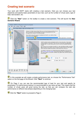
Cold Resistance TestResult 2.2KohmsTest lead positionSEPTEMBER 201011
Stabilized Current Test What is it? – Tests cable current at fullgvoltage– Insures cable power outputis correct for design andstable – Standard Multi Meter withp on currentclampattachement– Auto Range to 100 amps– Digital or Analog OK– Battery Operated BestInsulationWhen to do It?– After Insulation– At Start-up– PeriodicallyP i di ll permaintenance procedureEquipment How to do it–––––Watts Current * VoltageSEPTEMBER 2010–––Open UPC boxClClampontot one bbuss wireiEnergize circuitAllow circuit to run for 20minutes minimumTake current reading /recordDivide by circuit lengthMultiply by VoltageCompare to output at pipetemp12
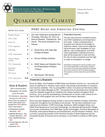
Stabilized Current TestOpen CoverClamp on buss wireRead ResultWatts Current * VoltageSEPTEMBER 201013
Stabilized Current TestWatts Current * VoltageComparepcalculated result to outputp chart at temppSEPTEMBER 201014
End of Circuit Voltage Test What is it?– Tests Voltage at end of Line– Verifies proper VoltageApplied– Verifies Buss wires aregood over entire length ofcable When to do?– At start-up– Periodically permaintenance procedure Equipment–––– How to do it––––––––SEPTEMBER 2010Standard Multi MeterAuto Range to 600 VoltsDigital or Analog OKBattery Operated BestDe-energize circuitRemove end capExpose buss wiresOne test lead to each busswireEnergize circuitR d voltageReadltCompare to desired valueRecord15
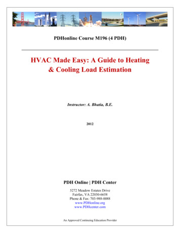
End of Circuit Voltage TestRemove CapSEPTEMBER 2010ExposepBuss Wires16
End of Circuit Voltage TestTest lead positionResult 120VacSEPTEMBER 201017
Maintenance General Considerations– All personnel should be qualified and trained to perform maintenancework.– All test equipment used should be in good repair and calibrated.– All inspection and test results should be documented on circuitmaintenancei tlog.l– Freeze Protection should be checked prior to cold weather each yearas a minimum.– Process Lines should be checked as the pprocess requires.q Mechanical Inspections– Follow same pprocedure as systemystart-upp Electrical Inspections– Follow same procedure as system start-upSEPTEMBER 201018
System Start – Megger Test Mechanical Checks Electrical Tests – Cold Resistance Test – Stabilized Current Test – End of Circuit Voltage Test Documentation Maintenance For Each Test – What is itWhat is it – Why do it – When to do it – How to do itHow to do it SEPTEMBER 2010 2. Overview SEPTEMBER 2010 3. System Start-up General Considerations – All .