Transcription
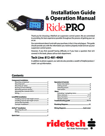
Installation Guide& Operation ManualThank you for choosing a RideTech air suspension control system. We are committedto providing the best experience possible throughout the process of getting your caron air.Our commitment doesn’t end with your purchase, in fact, it has only begun. This guideshould provide you with the information you need to properly install and set-up yoursuspension control system.However, if you find yourself having difficulty or if you have a question that isn’tcovered in this book, please call our tech department.Tech Line: 812-481-4969In addition to phone support, our web site also provides a wealth of helpful product /install / set-up information.ContentsComponent InstallationMounting compressor .2Mounting tank .2Mounting air valves .2Routing air lines & fittings .3Mounting pressure sensors.3Mounting the controls & ECU.3Wiring.3LevelPRO InstallationInstalling external ride height sensors.4Installing internal ride height sensors.4Sensor Rod Assembly .5Example installations .5AirPod InstallationMounting the unit .6Wiring.6Quick Start . 7Operation & ControlsButton description .8Setting presets .8Selecting presets.8Tank button.8MenuActivating / navigating menu .9Menu structure . 9-10Menu functions .11-12Remote control.12Troubleshooting guide .13-14Plumbing Diagrams.15Wiring Diagrams .back cover
Installing a RidePRO SystemRidePRO digital Part #: ARC4000digital ARC4100digital ARC4700digital ARC4800digital LevelPRO Part #: ARC4000L ARC4100L ARC4700L ARC4800LSTOPRemove the negative battery cable before beginningMounting the CompressorMounting the Air Tank All of our compressors are sealed for moisture and dust resistance sothey can be mounted anywhere on the vehicle. Although it is best tomount it in a place out of direct contact with rain and snow. It is OK tomount it underneath the vehicle but keep it inside the frame rails awayfrom water and debris thrown off the tire. The air tank can be mounted anywhere on the vehicle in any position,So long as the sensor is not pointed down. This is a dry compressor; therefore it is maintenance free and can bemounted in any position. It is best if mounted to something solid to reduce vibration andnoise. If mounting it to sheet metal or the bed of a truck usesound deadeningFilter / mufflermaterial between theinstall on inletcompressor and themounting surface. Use the rubbergrommets suppliedon the feet of thecompressor to reducevibration. Attach the grey wirefrom the main powerharness to the blackwire on the primarycompressor. The redwire connects to 12V There is an 1/8” port in the tank that will accept the tank pressuresensor.OKOKUse spacer forbetter coolingMounting the RidePro Air ValvesAlways userubber mounts The valves, like the compressor, are sealed and can be mounted in thesame locations. Although if the vehicle will be exposed to freezingtemperatures it is agood idea to mountthem in the enginebay if possible toreduce the possibilityof freezing. Thomas Compressors(black) will require a 20 amp fuse (each). They can be mountedin any position. Viair Compressor (silver) will require a 30 amp fuse (each). Attach the groundstrap to a good, cleanground (preferably theframe).Ensure agood groundis used The exhaust port willbe left open. The valve is held closed with the pressure in the tank. If tank pressuredrops below air spring pressure they will equalize, deflating all 4 airsprings.NOTE:The digital system switches ground on the compressors,the compressors are provided power at all times.( DO NOT INSTALL ADDITIONAL RELAY)The digital system monitors voltage and use of additional relay will cause error codes.2
Routing the Airline and Fittings Make all airline cuts with arazor or tubing cutter (part # 90001081).It must be clean and straight orit will not seal.Mounting the Air Pressure Sensors These sensors are voltage based and do not need to be grounded.Use Tubing Cutter(part # 90001081for straight ends. Use thread sealant when installing pressure sensors in valve block. Sensors can not be pointed down( debris can collect and cause false readings) All fittings are DOT approvedpush-to-connect style. Theyare very simple to use andare reusable. Firmly push theairline into the fitting to attach.To release the airline push the collar on the fitting back towards thefitting and pull the airline out. Use thread sealant on all fittings. Do not over tighten the fittings. This could result in breaking the fittingor damaging the air spring. All of our airlines are DOT approved so they are very strong. But keepthem away from any sharp edges. Also when passing through a hole inthe frame use a grommet.use threadsealant toavoid leaks Keep away from intense heat including mufflers and exhaust manifolds.Valve Connector Use zip ties or other fasteners to secure the airline.Power/RelayConnectorAir PressureHarness ConnectorMounting the ECU (Electronic Control Unit) & Control Panel The ECU is water proof and may be mounted in the engine bay or underthe vehicle. The control panel should be accessible from the drivers seat and may bemounted or left unmounted. The control panel cable uses mini USB connectors. Extensions canusually be found locally or purchased from RideTech.0.4603.8160.4602.477Main Power HarnessBlack wireA clean chassis ground3.8162.477Yellow wireIgnition(12 volts only when the key is on)Red wireConstant 12 volt1.723Grey WirePrimary Compressor Ground1.7235.0506.4616.461Height Sensor HarnessesBlue WireSecondary CompressorGround (OPTIONAL)DisplayConnector5.050Pressure HarnessDisplay / Controller HarnessRight FrontLevel SensorConnectorValve Block HarnessLeft FrontLevel SensorConnectorRight RearLevel SensorConnectorLeft RearLevel SensorConnectorMain Power3
Ride Height SensorsExternal LevelPRO Sensor Installation The LevelPro system uses 4 height sensors (one at each wheel). They are weather proof and may be mounted in any position as well as “clocked”in any position. (There is not a difference between the left and right sensors.) These sensors are typically mounted to the chassis / frame rail. A linkage with rubber ends connects the sensor arm and a suspension component. Onmost front suspensions the linkage will attach to the upper or lower control arm. On mostAttach to suspensionrear suspensions it will attach to the axle or control arm. The main goal when mounting the sensor is to achieve as much sensor rotation aspossible without exceeding the sensors limits. Although the sensor arm will rotate 180 degrees, it must remain in the middle 90 degreesthroughout suspension travel. See diagram below for sensor travel limits. It may be necessary to shorten the sensor arm and drill a new hole to ensure the arm isrotating enough during suspension travel to accurately determine vehicle height. The sensor arm can also be removed from the sensor and clocked in four differentpositions. It may also be necessary to bend the sensor arm and/or linkage to achieveproper clearance and alignment. The sensor will be mounted to the frame using ¼” self tapping screws or bolts. A specialshouldered bolt is supplied to attach the rubber rod ends to the suspension and thesensor arm, this will avoid over tightening.Attach to Make sure the sensor has adequate clearance from all suspension components throughout 90º ofChassiseffectivesuspension travel. Check tire clearance, lock to lock and throughout suspension travel.rangeTravel LimitsGoodTOO FAR! If the electrical range of travelis exceeded the system mayfunction erratically or not at all.! Also note that if the sensor hasGoodvery little travel the LevelProsystem may not perform to itspotential.! It may be necessary to shortenthe sensor arm to increasetravel.4
Ride Height SensorsAssembly of the LevelPRO Sensor Link Rods1- Once the linkage rod has been cutto the proper length assemble thelinkage rod with heat shrink tubingand the rubber end.2- Slide the heat shrink tubing over therubber end as far as it will go.4- Continue shrinking the tube to the roduntil secured. Be sure not to overheatthe tubing causing it to pull from therubber end.5- Once both sides of the linkage havebeen finished secure the linkage tothe sensor and suspension.3- Heat the shrink tubing with a heat gun(hair dryer or small torch will work).Begin by heating the rubber end first.The heat shrink is lined with adhesiveand will stick to the rubber when heat isapplied.Sensor Mounting Examples69 Camaro FrontRear Trailing Arm58-64 Impala Front65-70 Mustang RearTriangulated 4-Link RearC-10 Truck Rear5
Installing an AirPodAirPod Part #: APOD4000L APOD4000digital APOD4100L APOD4100digitalSTOP Remove the negative battery cable before beginning installation.MOUNT THE MAIN UNIT:1- Mount the base flat to the vehicle surface (do not bend the base)2- Secure the base with self tapping screws or bolts.3 - If Optional cover is used, Secure the cover to the airpod base using thesupplied screws.CONNECT AIR LINES:1 - Airline cuts must be straight and clean - use a razor blade ortubing cutter. (part # - 90001081)2 - All fittings are DOT approved, reusable, push-to-connect style.Firmly push the airline into the fitting to attach. To release theairline push the collar on the fitting back towards the fitting andpull the airline out.3 - All of our airlines are DOT approved so they are very strong.Secure the airline with zip ties, keep them away from any sharpedges and when passing through a hole in the frame use agrommet.CONNECT POWER HARNESS:1 - Connect the red power wire directly to thebattery.Use included fuse within 18” of battery.2 - Connect the yellow ignition wire to switched12v.(Fuse Panel is the best location)3 - Connect the black wire to chassis ground.CAUTION: Use 8 gauge wireor larger to extend red powerfeed if neededCONNECT LEVELPRO SENSORS(if equipped):See LevelPRO section for moreinformation on installing andcalibrating height sensors.CONNECT DISPLAY / CONTROLS:See control programming and additionalfeatures section for more information onusing the control panel.6Be sure to use includedfuse holder in the batteryfeed wire as close to thebattery as possible.POWER - REDSWITCHED- YELLOWGROUND - BLACKRF LF RR LR
CalibrationPress 3 to start setup.0Setup Required000Tank: 0Calibration:During the Calibration sequence the digital records information specific to the vehicle in which it is installed (inflate and deflate speed, if levelsensors are present, how long the compressors take to fill the storage tank, etc.) The digital then uses this information to attain the proper presetheights in the fewest possible steps, using the most intelligent method. For example, after calibration the digital knows that the front of thevehicle is heavier and therefore slower than the rear, so it will inflate the front first then allow the rear to catch up just as the vehicle is achievingride height.NOTE: The RidePRO digital system is a very intelligent system. Attempting to calibrate this system on a non running vehicle will cause errors.Trying to hook the system up for a “TEST RUN”? When the system is powered up it will work manually using the inflate and deflate buttons only.The preset buttons will not work until calibration is complete. Calibration should not be run until vehicle is running and driving.RidePRO SYSTEMS ( No Level Sensors)Calibration Steps: (items in red require user interface, other steps are automatically completed)These steps will require the car to be running to ensure full battery voltage!1. Start the vehicle2. Allow the compressor/compressors to fill the tank ( They will shut off @ 150psi )3. Press preset # 3 to start calibration.4. Release all air - this provides a solid starting point for the Calibration sequence5. Locating tank pressure sensor - locates and checks the tank sensor6. Locating air spring pressure sensors - locates and checks the air spring pressure sensors7. User must set Preset #2 - allows the user to set the Ride Height ( This can be changed later )8. Check vehicle speed to and from Preset #2 - the digital will utilize this information to achieve Ride Height in the fewest possible steps usingthe most intelligent method.9. Determines vehicle speed from lowered height to Preset #2 - the digital will utilize this information to achieve Ride Height in the fewestpossible steps using the most intelligent method10. Deflates down to Preset #1 - tests the system for deflating to Preset #111. Uses Calibration data to travel to Preset #2 - tests the system for inflating to Preset #2LevelPRO SYSTEMS ( with Level Sensors)Calibration Steps: (items in red require user interface, other steps are automatically completed)These steps will require the car to be running to ensure full battery voltage!1. Start the vehicle2. Allow the compressor/compressors to fill the tank ( They will shut off @ 150psi )3. Press preset # 3 to start calibration.4. Releasing all air - this provides a solid starting point for the Calibration sequence5. Locating tank pressure sensor - locates and checks the tank sensor6. Locating air spring pressure sensors - locates and checks the air spring pressure sensors7. User must raise to Max, then press and hold Preset #3 - sets the upper limit of suspension travel8. Locates level sensors - level sensors will be automatically displayed9. Determines suspension type - different suspension types will utilize different software to achieve preset heights10. User must set Preset #2 - allows the user to set the Ride Height11. Check vehicle speed to and from Preset #2 - the digital will utilize this information to achieve Ride Height in the fewest possible steps usingthe most intelligent method12. Determines how much air pressure is required to slightly lift the vehicle - this information allows the digital to more efficiently manageair usage13. Determines vehicle speed from lowered height to Preset #2 - the digital will utilize this information to achieve Ride Height in the fewestpossible steps using the most intelligent method14. Deflates down to Preset #1 - tests the system for deflating to Preset #115. Uses Calibration data to travel to Preset #2 - tests the system for inflating to Preset #216. Calibration complete7
Basic Operation & ControlsTankPressureLeft FrontLevel SensorPositionRight FrontLevel SensorPositionMenuButtonLeft FrontAir PressureRight FrontAir PressureLeft FrontInflateRight FrontInflateLeft FrontDeflate99995050PSILeft RearInflatePSIRight FrontDeflateINFLATE & DEFLATE BUTTONSYou have full manual control at any time. To inflate an air springsimply press and hold the corresponding “ ” button. To deflate anair spring simply press and hold the corresponding “-” button. Thecorresponding air spring will be inflated OR deflated until the buttonis released.PSIPSIRight RearInflate99995050PSILeft RearDeflateRight RearDeflateError WarningPreset #1Preset #2Preset #3IndicatorLeft RearAir PressureLeft RearRight RearLevel SensorLevel SensorPositionPositionPSIPSIPSIRight RearAir PressurePRESET BUTTONSThere are three preset buttons located on the lower portion of the display. These can be learned to any height,but normally they are set as: Deflated Setting Ride Height Inflated SettingSETTING PRESETSUse inflate and deflate buttons to obtain desired vehicle height. To store the height as a preset press and hold the preset button for 5 seconds ormore. The screen will display “Preset is saved” when completed99995050PSIPreset 2 savedPSIPSIPSISELECTING PRESETSTo select a preset press and hold the presetbutton for a half-second and no longer than5 seconds. (The delay is required to minimizeaccidental activation of presets.) The screenwill display “Preset selected” when activated.Press and hold for over 4.5seconds to store currentride height as a presetTANK BUTTONTank pressure can be viewed at any time by pressing the TANK button.The tank pressure will be displayed until the button is pressed again.899995050PSIPSIPreset 2 selectedPSIPSIPress preset for 0.5 second toactivate presetTANK PRESSURE:139 PSIPress TANK to exit.
Menu OptionsThe main menu is used to change system parameters, such as increasing the brightness of the screen, or themenu is used to access system information, such as viewing your preset pressures and level sensor settings.Main MenuAuto LevelingOFFDynamic LevelingDisplay OptionsSystem SetupWireless RemoteUPSELECTDOWNMENU STRUCTURETo enter the Main Menu simply press thebutton.Once in the menu you can scroll up using thebutton, or select a menu item by pressing thebutton, scroll down usingbutton.theYou may go back a screen by scrolling to the bottom of each page and selecting the “BACK” button, or bypressing thebutton.Main MenuLevel On StartONOFFDynamic LevelingONOFFDisplay OptionsTime Out FeatureOFF30 SECONDS60 SECONDS120 SECONDS300 SECONDSBACKScreen IntensityAUTOLOW INTENSITYMID INTENSITYMAX INTENSITYBACKKeypad IntensityAUTOLOW INTENSITYMID INTENSITYMAX INTENSITYBACKBACKSystem SetupCompressor On PSITURN ON PRESSUREBACKSystem InfoDISPLAY SW VERSIONECU SW VERSIONVOLTSBACKSystem AccuracySTANDARDMEDIUMHIGHBACKPreset SettingsView Preset 1L. FRONT PSI/VOLTAGER. FRONT PSI/VOLTAGEL. REAR PSI/VOLTAGER. REAR PSI/VOLTAGEBACKView Preset 2L. FRONT PSI/VOLTAGER. FRONT PSI/VOLTAGEL. REAR PSI/VOLTAGER. REAR PSI/VOLTAGEBACKView Preset 3L. FRONT PSI/VOLTAGER. FRONT PSI/VOLTAGEL. REAR PSI/VOLTAGER. REAR PSI/VOLTAGEBACKBACKRerun SetupARE YOU SURE YOU WANT TO RERUN SETUP?YESMenu Continued on Next Page. . .System Setup Continued on Next Page. . .NO9
MENU STRUCTURE (continued)Main Menu (Continued)System Setup (cont.)Lock PresetONOFFHide ErrorsONOFFBACKWireless RemoteLearn KeyfobsPress button 1 on each keyfob you want to useKeyfobs Found 0123BACKTroubleshootingLevel Sensor VoltagesL. FRONT VOLTAGER. FRONT VOLTAGEL. REAR VOLTAGER. REAR VOLTAGEBACKErrorsBACKAdvanced OptionsEnter CodeExit MenuMenu Options - DetailsAUTO LEVELDYNAMIC LEVELING:The Auto Level on Start feature is used to raise the vehicle to the #2Preset each time the ignition is turned on.Dynamic Leveling will automatically raise or lower the vehicle back tothe #2 Preset if the load changes while the vehicle is parked. As soonas the vehicle is in motion the system stops adjusting as it’s unsafe toalter air spring pressure while driving.ON:When vehicle is started it will return to the #2 Preset.OFF:When vehicle is started it will not automatically adjust to any setting10ON:The vehicle will return to the #2 Preset if the load changes.OFF:The vehicle will not adjust if the load changes.
Menu Options - DetailsDISPLAY OPTIONSDisplay Options allows you to change items such as the brightness of the screen or buttons as well as how long the screen will remainilluminated. OPTIONSLOW INTENSITY: The backlighting will remain at the lowest intensity.TIME OUT FEATURE:MID INTENSITY: The backlighting will remain at a medium intensity.The display screen and button backlights can remain illuminated at allMAX INTENSITY: The backlighting will remain at the brightest setting.times, or if you wish they can turn off after some time.KEYPAD INTENSITY:The intensity of the button backlighting can be automatically adjustedOFF: The display will remain on as long as the ignition is on.depending on ambient light conditions, or it can be changed to 330 SECONDS: The display will remain illuminated for 30 seconds.intensity levels.60 SECONDS: The display will remain illuminated for 1 minute.120 SECONDS: The display will remain illuminated for 2 minutes.300 SECONDS: The display will remain illuminated for 5 minutes.SCREEN INTENSITY:The intensity of the display screen backlighting can be automaticallyadjusted depending on ambient light conditions, or it can be changedto 3 intensity levels.AUTO: The backlight intensity will change with ambient lightconditions.SYSTEM SETUPSystem Setup allows you to change items such as system accuracy and compressor turn on pressure. You can also view system informationsuch as preset settings and software revision.COMPRESSOR ON PSI:The compressors can be configured to turn on anytime the pressuredrops below 125 to 140psi. Setting the turn on pressure higher willmake the compressors run more often, but for a shorter length of time.Setting the turn on pressure lower will make the compressors run lessoften, but they will run for a longer amount of time.SYSTEM ACCURACY:The System Accuracy feature allows the user to choose how precisethe system is when attempting to reach a preset destination. Thisfeature satisfies all drivers (some like to wait for the system to reachpreset before driving away while others want to start the car, throw itin drive and take off )STANDARD: The vehicle will reach the preset destination in as fewoperations as possible. This is acceptable for most applications.MEDIUM: The system will be slightly more precise than the Standardsetting which means it will take a few more steps to reach a moreprecise target.HIGH: This is the most accurate the system can be. It will take longerto reach the preset destination, but you can be assured that thevehicle is at the exact preset height.PRESET SETTINGS:Should you ever need to know the values that are saved for the threepreset settings they can be accessed here.If you are using an air only system you will only see pressure readingsfor each air spring.If you are using an air and level sensor system you will see both airpressure readings as well as level sensor voltage readings.RERUN SETUP:Should you ever need to recalibrate the system you may do so byrerunning the setup procedure.When you choose to rerun the setup you will be asked:“ARE YOU SURE YOU WANT TO RERUN SETUP?”You may select YES by pressing the “1” button, or select NO by pressingthe “3” button.SYSTEM INFO:This is where you find the software revision of both the display andECU as well as a volt meter to aid in troubleshooting.DISPLAY SW VER: This is the software version that is loaded into thedisplay.ECU SW VER: This is the software version that is loaded into the ECU.VOLTS: This is a digital voltmeter that will show you the voltage of thevehicle.Lock Presets:Lock presets gives the user the option to lock presets so they can notbe changed.Hide Errors:Gives you the option to keep all error codes from displaying on thescreen.11
WIRELESS REMOTE LEARN KEYFOBSMenu Options - DetailsThe Digital system has the capability of learning up to 4 remote keyfobs.Learning new keyfobs is as simple as entering the menu selecting remote function, and pressing the #1 button on each keyfob, one at a time,until all keyfobs are learned into the system. Each new keyfob will be recognized by the Digital system and the corresponding number will bedisplayed on the screen.REMOTE CONTROL INSTRUCTIONS1. Unplug the digital Display2. Plug the cable from the ECU into the smaller USB port of the Remote Module (USB Port; from ECU)3. Plug the supplied USB cable into the larger USB port of the Remote Module (USB Port; to Display)4. Plug the smaller end of the supplied USB cable into the digital Display5. Plug the antenna into the Remote Module (Antenna Port)6. Plug in the Ground Input harness if you are using custom switches (if you are not using customswitches you do not need to use the Ground Input harness.)USB PortGround Input7. Learn the keyfobs into the digital system by following the steps below.(to Display)PortProgramming Keyfobs:1- Once the Remote Module is installed you may learn the keyfobs into thedigital system.2- Enter the Menu via the digital Display3- Enter the “Wireless Remote” Menu4- Highlight the “Learn Keyfobs” Menu and Press # 2 (Select)5- Press the #1 preset button the first keyfob6- Press the #1 preset button on the second keyfobAntenna PortUSB port(from ECU)OPTIONALGround Input Harness:The digital Remote Module allows you to trigger the three presets with custom switches or any auxiliary devicethat supplies a ground output (car alarms, remote shaved door kits, etc.)If you are using custom switches:1- You will need to source momentary contact switches. Connect one side of each switch to ground.(A black ground wire is supplied in the 4 pin connector)2- Connect the other side of the switch to the corresponding colored wire of the Remote Module:Blue – Preset 1 Yellow – Preset 2 Grey – Preset 3 Black – Ground3- Once the digital system goes through Calibration the Display can be removed. The 3 ground inputs can be used at any time.TROUBLE SHOOTINGThe Digital system keeps a log of each error message that has been triggered. You may enter the Troubleshooting area of the menu for! indicated by a (on the main screen) Simply select the error you wish to resolve and the Digitalassistance in resolving any error. (errors aresystem will walk you through the same steps our tech support staff uses to help you resolve the issue.LEVEL SENSOR VOLTAGEThe level sensor voltage allows you to check the voltage at the level sensor at certain heights. If the level sensor is out of range it can be checkedhere.ADVANCED OPTIONSThe Advanced Options menu is a place where we keep tools and utilities to assist our staff in setting up or troubleshooting any area of theDigital. The Advanced Options menu is accessible only with a pass code.12
Troubleshooting GuideCompressor will not turn on.Compressor will not turn off.Diagnosis A: 12 volts not present atDiagnosis A: Tank pressure reads 0Red wire on compressor.psi all the time or staysat the same pressureregardless of actualSolution A: Check fuse andtank pressure.connections.(20 amp fuse onThomas compressor)Solution A: 1. Check harness and(30 amp fuse on Viairplugs.compressor)2. Replace pressuresensor.Diagnosis B: 12 volts present at redwire on compressor but Diagnosis B: Tank pressure buildsstill doesn’t run.normally but will notreach 150psi.Solution B: 1. Check connectionsbetween Black wire onSolution B: Replace compressor.compressor and Blue/Gray wire on ECU. Alsocheck Black wire fromECU to Ground.All 4 air springs leak down over aperiod of time.Diagnosis A:Check tank pressure.There is a leak in thesupply side of thesystem. This could beat the comp. , tank, orsupply ports on thevalve.Solution A:Spray all fittings withsoapy water. Tightenfitting and/or removeand replace threadsealant. Cut 1” offof end of airline andreinsert.Presets work,but does not achieve target.Diagnosis A: Leak between delivery porton valve block and air spring.Solution A:Air springs almost neverleak. Spray all fittingswith soapy water. Tightenfitting and/or remove andreplace thread sealant. Cut1” off of end of airline andreinsert.Diagnosis B: Exhaust valves leaking. Airseeps past exhaust valve andout exhaust port.Solution B:Usually caused by debrisstuck on valve seat. Inflateand deflate several times ordisassemble valve.Presets work,but does not achieve target.Diagnosis A: Air tank is too small.Air spring pressureequalizes with tankpressure beforeachieving presetpressure/height.Diagnosis C: Pressure sensors and/orairline are not attached tocorresponding air spring.(Ex: RF button must activateRF air spring and top rightnumber on display.)Solution A:Solution C:Reprogram #1 presetfor the highestpsi that allowsthe suspension tobottom out. Will giveit a “head start”.Diagnosis B: Tank pressure leaksdown.Solution B:NOTE:One air spring leaks down over aperiod of time.Fix leak on supplyside of system.Target on pressure based systems is or - 7 PSITarget on height based systems is or - 1/4”Swap airline at delivery porton valve and/or air pressuresensor harness’s.Diagnosis D: Mechanical height sensorsare out of range. Under“System Setup” check thepresets voltages. If oneor more are at 4.5v or .5vthen the sensor is travelingbeyond it’s range of travel.Solution D:Reduce or change travel ofsensor by either changinglinkage length, changingsensor arm length or byrotating sensor.13
Troubleshooting GuidePressure reading are notmoving, always reads 168 psi or0 psi.Diagnosis :ECU is not receiving aproper signal from thesensor.Height sensor bars read theincorrect corner.Diagnosis : Ex: When inflatingRF air spring LF barincreasesSolution:Solution :1. Check pressuresensor harnessconnections.Control panel switches do notactivate the correct air spring.Diagnosis :Ex: LF switch actuatesthe RF air spring.Solution :Swap airline at thevalve block.Swap height sensorharnesses at ECU.2. Replace sensor.Control panel switches activatethe correct air spring, but the airpressures read the wrong airspring.Diagnosis :Solution:Ex: Inflating the RF airspring changes thetop left psi readout onthe panelSwap pressure sensorharnesses at thesensors.Wireless remote control doesnot funct
CONNECT AIR LINES: 1 - Airline cuts must be straight and clean - use a razor blade or tubing cutter. (part # - 90001081) 2 - All ttings are DOT approved, reusable, push-to-connect style. Firmly push the airline into the tting to attach. To release the airline push the collar on the