Transcription
ReviewCHINA FOUNDRY SpecialVol. 18 No. 4 July 2021https://doi.org/10.1007/s41230-021-1099-2Rapid casting technology based on selective lasersinteringLi Yang, Shi-yan Tang, *Zi-tian Fan, Wen-ming Jiang, Xin-wang LiuState Key Laboratory of Materials Processing and Die & Mould Technology, School of Materials Science and Engineering, Huazhong Universityof Science and Technology, Wuhan 430074, ChinaAbstract: Selective laser sintering (SLS), as a kind of additive manufacturingtechnology, which uses a laser beam to scan and heat powder material layer by layerto form parts (models), is widely used in the field of casting, mainly for preparing castingcoated sand cores, investment casting patterns, etc. The SLS technique facilitates rapidcasting and shortens the casting production periods by eliminating mold preparation. Inthis study, we reached conclusions for the basic principles and characteristics of SLSmethods, and focused on the research status, key technology and development trend ofSLS in the fields of forming coated sand-casting molds and investment casting patterns.Key words: selective laser sintering; additive manufacturing; rapid casting; coatedsand; investment casting patternCLC numbers: TG221; Document code: A; Article ID: 1672-6421(2021)04-296-111 IntroductionLi YangPh.D, Postdoctoral Fellow (HuazhongUniversity of Science and Technology).His research interests include rapidcasting technology, and materials,technology and equipment of ceramicadditive manufacturing. He has obtainedthe Postdoctoral Innovation Post Fundingof Hubei Province, presided over oneInnovation Fund of Huazhong Universityof Science and Technology, participatedin one National Major Research &Development Program of China and twoNational Natural Science Foundation ofChina. He has published 16 researchpapers in journals and conferences, andpossesses three invention patents of China.E-mail: yanglicl@hust.edu.cnCorresponding author:*Zi-tian FanE-mail: fanzt@hust.edu.cnReceived: 2021-05-17Accepted: 2021-08-23296Selective laser sintering (SLS) technology adopts a high-power laser beam to selectivelyirradiate the surface of the target powder bed. The powders then are heated and sintered(i.e., interparticle fusion) for bulk joining. After one layer is completed, the platformwill descend in an increment of one-layer thickness, and a new layer of powder is spreadonto the previous surface for the next run of heating and joining, so that the 3D parts arestacked layer by layer, and finally the unfired powder is removed to obtain the parts [1].SLS was invented by Deckard and Beaman at the University of Texas at Austin, withthe very first patent filed in 1986 [2], and was further developed by the DTM company.The first SLS equipment was developed in 1988. The Sinter Station 2000, a commercialproduction facility, was launched by 3D Systems Company in 1992. The Germanycompany EOS successively launched three series of SLS forming equipment in 1994. Fordecades, the University of Texas at Austin and the DTM company (3D Systems) in theUnited States performed a lot of research works in the SLS field, including equipmentdevelopment, process and material development [3-4].Domestic research on SLS technology began in the 1990s. Beijing Longyuan AFSCo., Ltd. successfully developed the first AFS selective laser sintering machine in early1995. The research group in Huazhong University of Science Technology (HUST)carried out the research and development of the SLS equipment system, and launched thecommercial HK series powder sintering equipment [4]. Recently, the domestic institutionsengaged in SLS technology research mainly include: HUST, Beijing University ofAeronautics and Astronautics, Nanjing University of Aeronautics and Astronautics,Dalian University of Technology, Southwest Jiaotong University, North University ofChina and other universities and research institutions [5].SLS technology plays an important role in manufacturing complex, lightweight, thinwalled parts, and developing new products. The United States, Japan and Western Europeand other countries have studied the application of 3D printing technology in the fieldof traditional casting since the 1990s [6]. For example, Pratt & Whitney Laboratory in
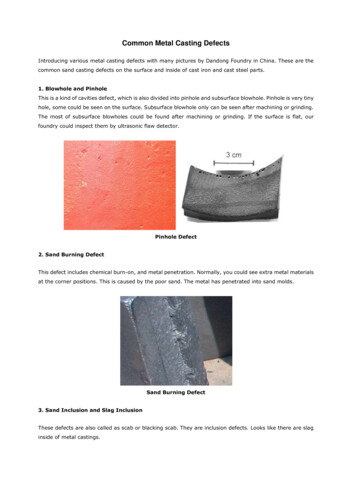
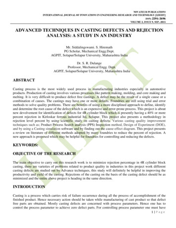
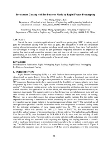
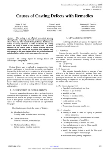
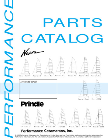
Special Review CHINA FOUNDRYVol. 18 No. 4 July 2021the United States manufactured more than 2,000 castings in1994 using 3D printing technology combined with traditionalcasting technology [7]. At the same time, HUST and BeijingLongyuan Co., Ltd. also began to apply SLS technology torapid casting [8-9]. For instance, the team from HUST usedthe self-developed SLS system to prepare coated sand moldsin 1998 [10]. Compared with other additive manufacturingtechnologies, SLS technology possesses the advantages ofabundant material selection, non-toxicity, and easy storage. Inaddition, the process is simple and does not require additionalsupport structures, which is especially suitable for smallbatches of personalized customization parts with complexshapes and structures [4].In this study, the basic principle and characteristics of SLSpowder technology were introduced, and the research status,key technologies and development trend of SLS in the fieldsof forming coated-sand mold casting and investment castingpattern were mainly described.in Fig. 1. It has a wide range of forming materials, includingcoated sand, polymer, ceramics and other powder materials.Figure 2 shows coated sand core, wax based casting patternand ceramic parts prepared by SLS technique [13]. At present,the major SLS forming equipment manufacturers, bothdomestic and abroad, include: 3D Systems, EOS, BeijingLongyuan AFS Co., Ltd., Huake 3D Technology Co., Ltd.,Farsoon Technologies, etc [11]. Table 1 shows some equipmentmodels and parameters.2 Basic principle and characteristicsof SLSThe working principle of selective laser sintering is shownFig. 1: Schematic diagram of selective laser sintering [12](b)(a)(c)Fig. 2: Images of different items formed by SLS of various materials: (a) coated sand; (b) wax pattern; (c) ceramics [13]Table 1: Manufacturers and parameters of SLS equipment at home and abroad [14-18]Manufacturer3D SystemsEOSBeijing Longyuan AFSHuake 3D TechnologyFarsoon TechnologiesBuild dimension(mm3)Laser typeModelLayer thickness(mm)Scanning speed(m·s-1)550 550 750CO2, 70 WsProTM 2300.08-0.1510381 330 460CO2, 70 WProX SLS 61000.08-0.1512.7700 380 380CO2, 70 WEOS P8100.126200 250 330CO2, 30 WFORMIGA P 110Velocis0.06-0.10-0.1251,050 1,050 650CO2, 120 WLaserCore-60000.08-0.356700 700 500CO2, 55 W or 120 WLaserCore-53000.08-0.3561,400 1,400 500CO2, 100 WHK S14000.08-0.38800 800 500CO2, 100 WHK S8000.08-0.381,000 500 450CO2, 100 WHT1001P0.06-0.315.2400 400 450Fiber laser 300 WFlight 403P0.06-0.320297
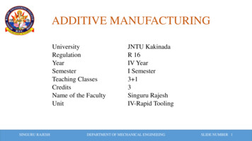
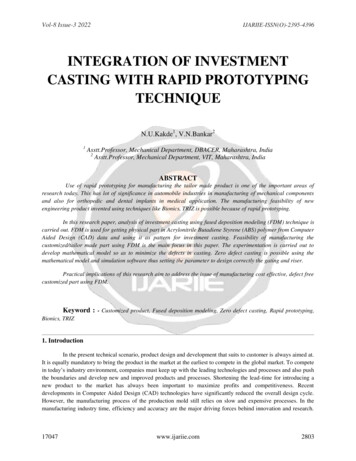
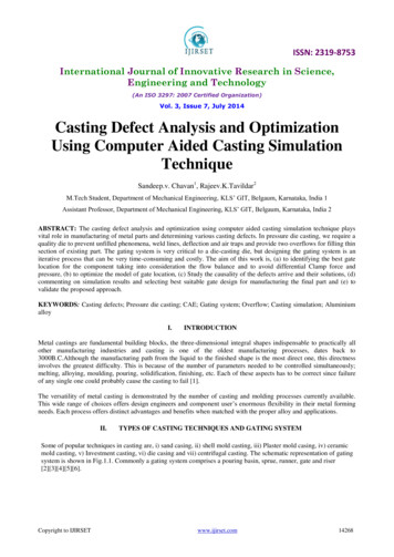
ReviewCHINA FOUNDRY SpecialVol. 18 No. 4 July 2021The application of SLS in the field of casting focuses onsand casting, investment casting, etc., specifically including:(1) using SLS technology to prepare investment patterns (waxpattern, resin pattern, etc.), and then combining investmentprecision casting to obtain metal castings; (2) directlypreparing the sand mold (core) for casting based on coatedsand as sintered material, followed by metal casting to obtainmetal castings.Due to the higher melting temperature of ceramic material,the laser beam adopted in SLS equipment can hardly sinterceramic particles together in a short period of time. Recentstudies [13] have focused on mixing ceramic powders withpolymer adhesives to prepare ceramic parts based on the SLSmethod, followed by debinding and sintering to obtain complexceramic shell (core); but a ceramic shell (core) formation basedon the SLS method has been rarely reported.2.1 SLS in sand castingSand-mold casting, as the widely adopted manufacturing methodin the traditional casting process, has great dependence on sandmolds to determine the metal casting quality. The traditionalmanufacturing process of a sand mold (core) is complex, andthe production cycle is long, especially for the sand mold (core)used in the production of various large and complex castings,which is often composed of multiple sand molds (cores). It iswidely recognized that the assembly positioning accuracy is low,the surface quality is poor, and the cutting allowance is large,which leads to a lot of waste of raw materials, greatly increasesprocessing cost, and seriously reduces production efficiency.SLS, as an additive manufacturing method, could directlyfabricate sand molds with complex structures by sintering thecoated sand particles, which has attracted great attention from(a)both academic and industry fields.The experimental study of direct sintering with coatedsand as sintering material began in Europe in 1996 (such asEOS company in Germany) [8]. At the same time, ProfessorFan systematically studied the process parameters of makingcoated sand mold (core) by SLS, analyzed the mechanism andcharacteristics of heat hardening of coated sand under laserirradiation, and poured a variety of metal castings [9, 19-22].It is an outstanding application of rapid prototyping technologyin the foundry industry that coated sand is used as sinteringmaterial, and the SLS method is used to directly form the mold(core) for casting [9, 23-24]. Compared with the traditional sandmold casting method, the complex and bulky casting productionprocess can be completed on the SLS machine, saving a lot oftooling equipment (forming machine, core making machine,transportation equipment, etc.), breaking through the bottleneckof complex sand mold (core) manufacturing difficulty and longproduction cycles [25-26]. As shown in Fig. 3, the sand molds ofa hydraulic multi way valve were prepared by SLS, and thecasting was obtained after pouring. The SLS prepared sandmold exhibited integrated appearance, and after casting, therelevant hydraulic valve casting with desired structures andsurface quality was obtained.2.2 SLS in investment castingInvestment casting can produce metal parts with a high surfacefinish and complex shape, and the corresponding preparationprocesses mainly include preparation of wax pattern, assemblyof wax pattern, preparation of multilayer ceramic shell,dewaxing, shell sintering, pouring, removal of ceramic shelland post-treatment [28-31], which has a long production cycleand many technological links.(b)(c)Fig. 3: SLS and sand casting: (a, b) sand mold of hydraulic multi way valve; (c) hydraulic valve casting blank [26]298
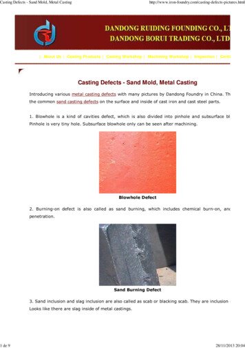
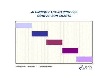
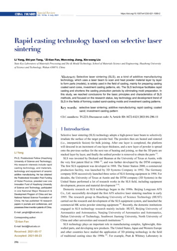
Special Review CHINA FOUNDRYVol. 18 No. 4 July 2021Directly forming polymer-based patterns (wax pattern, resinpattern, etc.) through SLS method provides a novel solutionfor investment casting pattern preparation [32-33]. SLS techniquehas been adopted in investment casting since the 1990s. DTMcompany was the first, and then HUST, Nanjing Universityof Aeronautics and Astronautics, and Beijing Longyuan AFSCo., Ltd. in China, carried out relevant research [7, 34-35]. Acomposite manufacturing procedure mixing SLS techniquewith investment casting can break through the limit oftraditional pattern design, save the pattern development andmanufacturing process, and shorten the production cycle. Asshown in Fig. 4 [12], the casting polystyrene (PS) pattern isobtained by using SLS method and then followed by surfacedipping wax, wax pattern assembly, shell making and pouring,after that, a rapid die-less manufacturing of a engine cylinderblock is realized.(a)(b)(c)(d)Fig. 4: SLS combined with investment precision casting: (a) wax pattern of SLS cylinder body; (b) wax patternassembly; (c) shell making; (d) cylinder block casting [12]3 Key technologies in SLSSLS can rapidly prepare complex prototype parts andfunctional parts without additional support structure basedon large variety of materials. It plays an important role in thefield of additive manufacturing, and its main application inthe casting field is the preparation of a coated sand mold andinvestment pattern, replacing the wax pattern in sand moldcasting and investment casting.3.1 Materials adopted in SLS technique3.1.1 Precoated sand materialsAccording to the sintering and binding mechanism, coatedsands adopted in SLS technology contain sand particles andbinders that cover around the sand particles. The shape and sizedistribution of sand particles directly influence the formability,normally with a spherical shape and average diameter lessthan 0.20 mm. Besides, binders used for coated sands arecarefully formulated to combine the properties of rapidlybinding the sand during laser processing and then improvingstrength during the drying processing. The coated sandsadopted in SLS method are prepared using thermoplastic orthermosetting resin including phenolic resin coated quartzsand, zirconium sand or pearl sand [34]. Normally, the coatedsands suitable for SLS method have good thermal conductivity,formability and thermoset, small diameter (less than 0.20 mm),low gas evolution, and narrow softening temperature range.Furthermore, after laser sintering, the sand molds should havesufficient strength, and the waste residues should be easilyremoved.3.1.2 Materials for investment patternsDifferent from general patterns for investment casting, SLSbased pattern material as a polymer possesses high molecularweight, high melting temperature, no fixed melting point anda wide melting range. Due to the high viscosity of the moltenpolymers, high temperature is required to realize the dewaxing,thus, common water boiling or steaming cannot be adopted todewax.The main materials used to prepare the investment patternsare amorphous polymer materials, which possess an irregularand amorphous molecular chain, high melting viscosity,and correspondingly low sintering rate, resulting in lowdensity, porous structure and poor strength of SLS formedparts. However, due to the small shrinkage deformation ofamorphous polymer in the SLS forming process, the formingparts have high dimensional accuracy. Therefore, amorphouspolymers are usually used to prepare products with low299
ReviewCHINA FOUNDRY SpecialVol. 18 No. 4 July 2021strength requirements but high dimensional accuracy, such aspolycarbonate (PC), polystyrene (PS), high impact polystyrene(HIPS), etc., which are used in investment casting.3.2 SLS formation processThe SLS equipment system is mainly composed of three parts:computer control system, host system and cooling system [9].(1) Computer control system is in charge of three-dimensionalmodel processing, real-time control and simulation in themachining process.(2) Host system consists of working cylinder, powderfeeding cylinder, powder spreading system, galvanometer laserscanning system, temperature control system, fuselage andcasing.(3) Cooling system is adopted to cool the laser device,improve the stability of laser energy, protect the laser, extendits service life, and cool the galvanometer scanning system toensure its stable operation.In the SLS process, the powder under the laser irradiationgenerally goes through three stages: heating process, sinteringprocess, and cooling process [36], as shown in Fig. 5. For coatedsand and polymer materials, different forming requirementsand mechanisms are required. The forming process of twodifferent materials is discussed briefly below.Specific heat flow (W·g-1)T c peak3.2.2 SLS formed investment patternsSLS sinteringwindow:ΔT Tm onset - Tc onsetΔHcTc onsetCoolingTm onsetHeatingBThe heat curing of coated sand under laser irradiation isdifferent from that of a shell mold (core) in casting production.When the surface of coated sand is scanned by laser beam,the conversion of light energy absorbed by the surface ofcoated sand to heat energy occurs instantaneously. At thismoment, the heat energy is only limited to the laser irradiationarea on the surface of coated sand. Through the subsequentheat conduction, the heat energy transfers from the hightemperature region to the low temperature region. Therefore,a temperature gradient is formed between the surface and theinner layer, and the surface temperature of the coated sandcontacted by the center of the laser beam is usually the highest.Although the instantaneous temperature of laser heating isvery high, the duration is short, and thus, it is difficult tothoroughly melt and solidify the resin on the surface of coatedsand, resulting in partial solidification [9, 39].After scanning the sand surface with laser beam, thesolidification degree of coated sand is related to the spotdiameter d0, scanning distance P, and thickness of sintered sandlayer δ. When the laser output power and scanning speed areconstant, the corresponding thickness h0 of the specific coatedsand can solidify and the softening bond depth h W can beregarded as constant. To generate connection among layers, thethickness of sintered sand layer δ should meet the requirementof δ hW [9, 39].AΔHmTm peakTsTemperature ( C)Fig. 5: Heating/cooling process of powders in SLS forming [36](Tc: crystallization temperature, Tconset: starting temperature of crystallization,Tcpeak : maximum temperature of crystallization, Tm: melting temperature,T monset : starting temperature of melting; Tmpeak: maximum temperature ofThe sintering mechanism of polymer powders in the SLSprocess is shown in Fig. 6 [40]. During the sintering process,the powder at the center of the laser spot reaches the meltingpoint first to form a melting pool rapidly. Then, with thecontinuous action of the laser energy, the unmelted powderin the zone of action begins to melt and flows to the moltenpool. When the laser moves away rapidly, the molten poolsolidifies with the decrease of temperature, and the whole partgradually cools down. The new layer is sintered by the laserand simultaneously bonded to the previous layer. This processrepeats until the final 3D physical part is produced.In the SLS forming process, the preheating temperatureof amorphous polymer material should not exceed its glassmelting, ΔHc: heat release of crystallization process, ΔHm: heat adsorptionof melting process)3.2.1 SLS formed coated sandDuring laser sintering, the binder on the surface of sand particlesmelts, solidifies and hardens to form a connecting bridge asthe medium among the sand particles to connect the dispersedsand particles [36-38]. Due to the difference between SLS formedcoated sand mold/core and traditional sand mold/core, thefollowing points should be considered in the process design ofSLS mold/core: (1) the sintering area of the first layer shouldnot be too small; (2) an inverted trapezoid structure shouldbe avoided to prevent warpage; (3) a sintering island shouldbe avoided in the sintering process; (4) a cantilever structureshould be avoided [9].300Fig. 6: Sintering mechanism of polymer powders of SLSprocess
Special Review CHINA FOUNDRYVol. 18 No. 4 July 2021transition temperature (T g) to reduce the warpage duringsintering formation. Theoretically, increasing the laser energydensity facilitates improving the density and strength of thesintered parts, but too high a laser energy density will reducethe strength of the sintered parts, deteriorate the dimensionalaccuracy and appear warpage [4]. Therefore, the main processparameters (laser power, spot size, scanning distance, scanningspeed, single layer thickness, powder bed temperature, etc.) ofSLS forming should be comprehensively considered to obtainthe investment pattern with better performance and surfacequality.3.2.3 SLS forming process simulationThe forming process of SLS is extremely complex. During theforming process of coated sand and polymer molds (cores),the laser heat source melts the material through heat transfer,convection and radiation. The finite element method can beused to simulate the thermal effect of the sintering processand the flow process of the molten powder material. In recentyears, the numerical simulation of the SLS has been a greatconcern to experts and scholars at home and abroad. The finiteelement model is established by finite element software tosimulate the temperature field and stress field of the SLS andto optimize the process parameters.Liu [41] carried out the multi-field coupling simulationanalysis of the coated sand sintering process to obtain thetemperature field data and a multi-particle model for sinteringneck. In addition, the variation law of processing parametersand binder ratio on the simulation results was discussed, andthe results indicated that as the sintering time was 400 ms,strong sintering necks among particles were generated, and asthe binder content (thermoplastic phenolic resin) was 6%, thesize of sintering neck reached 35 μm. The simulation resultsprovide theoretical support for the preparation of coated sandmaterials and optimization of sintering process parameters.Yan et al. [4] established a numerical simulation technologyroute for the composite process of cold isostatic pressing (CIP)and furnace sintering (FS) for selected laser sintering aluminaceramics. It lays the foundation for the SLS/CIP/FS compositeprocess to form complex ceramic parts and improves theforming accuracy of the parts.Meng et al. [42] developed the finite element simulationsoftware and investigated the effects of laser power, laserscanning rate and preheating temperature on the SLS peaktemperature during the numerical examples. The peaktemperature increases with the increase of laser power andpreheating temperature, and decreases with the increase oflaser scanning rate. The scanning path has negligible effect onthe peak temperature of polymer powder during SLS process.Peyre et al. [43] carried out a dual experimental-numericalapproach to estimate thermal cycles and sintering thicknessobtained during SLS of PA12 and PEKK. The numericalcalculations indicate that most of the incident laser light iseither reflected or diffused in the powder bed.In summary, recent simulation on the SLS process hasfocused on the temperature field concerning SLS processconditions and material parameters, but few works discussthe flow of melting model and bonding mechanism. Futureresearch on finite element simulation on flow models ofcoated sands and polymer molecules during the SLS processshould be carried out, which will greatly benefit enhancing thesurface and dimension accuracy. Simulation combining theSLS process and specific casting process remains as anotherpromising field in further research.3.3 Post-treatment for SLSPost-treatment (heating curing, surface finishing, dip coating,etc.) is necessary for SLS prepared samples to improve thesurface quality and enhance the strength. There are differentpost-treatment methods corresponding to different SLSmaterials.3.3.1 Post-treatment for SLS formed coated sandThe initial strength of coated sand hardened by laser beamscanning irradiation is relatively weak, and the correspondingexplanations are: (1) the irradiating time of laser beam is veryshort; (2) the thermal conductivity of coated sand is low;(3) the maximum heating temperature of beam irradiation isnot allowed to be too high (when the maximum temperatureis higher than 300 C, the resin film is heated and carbonized).The thickness of the sintering layer, the thermal conductivityof the material, and the irradiation temperature of the laserbeam (mainly depending on the output power and scanningspeed of the laser beam) have great influence on the sinteringstrength. Besides, the coated sand mold (core) formed by SLSmust be cured to meet the requirements of metal casting.In addition, the surface of the sand mold is rough due tothe step effect during formation. For the SLS mold (core)with split sintering, the inner wall of the mold cavity can bepolished after heat preservation treatment to reduce the surfaceroughness of the mold cavity; for the SLS mold (core) withintegral sintering, a coating procedure is necessary to improvesurface quality. After coating, the mold (core) should be driedtwice to remove the moisture and volatile matter in the coating.3.3.2 Post-treatment for SLS formed investment patternDue to the high porosity, low strength and rough surface ofthe investment pattern parts formed by SLS, it is necessaryto carry out post-treatment. At present, the widely adoptedmethod is wax or resin infiltration, which could enhancesurface accuracy and strength concurrently, and also benefitsubsequent polishing. In addition, in order to meet therequirements of investment casting, the SLS pattern must becompletely removable or burnt out during dewaxing.4 Practical applications of SLS inrapid castingAs previously mentioned, the applications of SLS method inrapid casting mainly include sand-mold casting and investmentcasting. In this section, several practical applications areintroduced in detail.301
ReviewCHINA FOUNDRY SpecialVol. 18 No. 4 July 20214.1 SLS application in sand-mold castingThe application of SLS-based rapid casting has focused onmold forming. Currently, the poor formability of coated sandmold (core) remains as an important problem at this stage, andcurrent research on SLS molding coated sand focuses on thematerial selection, optimization of process parameters, andimprovement of mold (core) strength and accuracy.Wen et al. [44] prepared a large sand mold for a complex six-(a)(c)cylinder diesel engine cylinder head by SLS technology basedon new adhesive coated alumina sand, and finally obtainedcastings with surface quality and dimensional accuracy tomeet the design requirements. The sand mold and castingsare shown in Fig. 7 [44]. The materials and method proposednot only shortened the trial production cycle of the six-cylinderengine from five months for the traditional casting method to 10days, but also reduced the cost and improved the casting quality.(b)(d)Fig. 7: SLS-based sand mold and casting: (a, b) sand mold; (c, d) casting of cylinder head of six-cylinder diesel engine [44]Liang et al. [45] prepared coated zircon sand by thermal orcold coating method, and studied the influence of the singlescanning area, and the laser power of SLS on tensile strengthof the coated zircon sand molds. The results showed that withthe same resin content, the tensile strength of the SLS formedby the thermal coating method was higher than that of thecold coating method. As the single scanning area increased,the corresponding tensile strength of the coated zircon sandmold was decreased. Besides, as laser power increased, thecorresponding tensile strength was enhanced, but as the laserpower exceeded 45 W, the sand mold surface quality wasdecreased due to sand clogging. As the binder content of115/170 mesh coated zircon sand was 2%, the scan area wasabout 1900 mm2, appropriate laser power was 35 W, the zirconcoated sand molds were successfully prepared, and the titaniumcastings with clear outline and bright surface were cast.Xu et al. [46] studied the influence of laser energy densityon the precision and tensile strength of SLS resin coatedsand. The coated sand was coated with 1.5wt.% resin with aparticle size of 75-150 μm. The experimental results showedthat as the energy density range of laser sintering was 0.0240.032 J·mm-2, the tensile strength and dimensional accuracy ofthe sample were the best, and the composite coated sand moldwith clear shape and high molding accuracy was successfullyprepared, as shown in Fig. 8.Cheng et al. [47] studied the optimization design of SLSprocess parameters of a precoated sand mold. The effectsof laser power, scanning speed, layer thickness, scanningdistance, and their interactions on the dimensional accuracy302Fig. 8: Composite coated sand mold prepared by SLS [46]of coated sand mold SLS were studied. The results showedthat the dimension error along the length and width of thedie was dominant. By using Taguchi's parameter design, thebest parameter setting was settled to minimize the size error.The optimum parameters were obtained: laser power 11 W,scanning speed 1,200 mm·s-1, layer thickness 0.5 mm, andscanning spacing 0.25 mm. The dimensional accuracy of thecombination of these parameters could be increased by about25% on average.Although the sand particles and binder system adopted inthe SLS technique are similar to those adopted in conventionalsand molding method, after optimizing processing parameters,the sand molds or cores prepared through the SLS method showcomparative properties compared to conventional methods, asshown in Table 2.
Special Review CHINA FOUNDRYVol. 18 No. 4 July 2021Table 2: Comparisons of materials and properties of SLS method and conventional methodMethodsSand particleBinder systemMixture of phenolic100-210 μm Al2O3sand particles: regularresin andspherical shapehexamethylenetetramineSLS techniqueConventional sandmoldingProcessing conditionsLaser power: 50 W;layer thickness:0.25-0.30 mm;Scanning speed: 4 m·s-1Zircon sand:90-125 μmThermoplastic phenolicresinLaser power: 35 W;Scanning area:3 19 cm2Spherical Baozhusand: 75 to 150 μm,angular coefficient 1.1Thermoplastic phenolicresin, methenaminecuring agent and KH550coupling agentLaser power: 30-40 W;Scanning speed:1.5-2.0 m·s-1Phenolic resinCuring temperature:85 C;Holding time: 120 minSpherical sands:100-270 μmPropertiesReferenceTensile strength:6.85 0.46 MPa;[44]Gas content at 1,000 C:21.83 0.58 mL·g-1Tensile strength:3.2 MPaGas content: 30 mL·g[45]-1Tensile strength:0.34 MPaDimensional accuracy: 0.25%Tensile strength:1.35 MPa;Gas content:7.83 mL·g-1[46][48]4.2 SLS application in investment castingAnother important application of SLS technology in thecasting field is to prepare the investment pattern. Polycarbonatewas firstly developed for SLS forming polymer patternsbecause of its excellent laser sintering performance and highstrength. However, the melting point of polycarbonate isrelatively high, and the fluidity is not good, so it needs a highercalcination temperature. Nowadays, polystyrene and highimpact polystyrene are widely used as raw materials in SLStechnology to prepare an "investment pattern".Sun et al. [49] prepared polystyrene-wax composite patternsbased on SLS techni
the casting field is the preparation of a coated sand mold and investment pattern, replacing the wax pattern in sand mold casting and investment casting. 3.1 Materials adopted in SLS technique 3.1.1 Precoated sand materials According to the sintering and binding mechanism, coated sands adopted in SLS technology contain sand particles and