Transcription
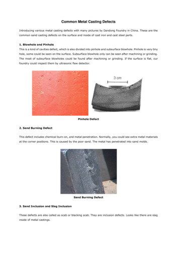
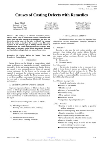
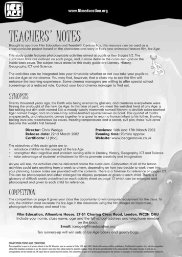
Investment Casting with Ice Patterns Made by Rapid Freeze PrototypingWei Zhang, Ming C. LeuDepartment of Mechanical and Aerospace Engineering and Engineering MechanicsUniversity of Missouri – Rolla, Rolla, MO 65409-0050, E-mail: mleu@umr.eduChao Feng, Rong Ren, Renjie Zhang, Qingping Lu, Jubu Jiang, Yongnian YanDepartment of Mechanical Engineering, Tsinghua University, Beijing 100084, P. R. ChinaABSTRACTOne of the most promising applications of rapid freeze prototyping (RFP) is making metalparts by investment casting with the built ice parts. The integration of RFP and investmentcasting allows fast creation of complex net-shape metal parts directly from their CAD models.The advantages of doing so include no part geometric complexity limitation, no experience ofparting line design and assembling needed, clean and low-cost of process operation, and goodperformance. In this paper, we will present our recent study on binder selection, slurry making,ceramic shell making, and the casting results of the metal parts.KEYWORDSSolid Freeform Fabrication, Rapid Prototyping, Rapid Tooling, Rapid Freeze PrototypingIce Patterns, Investment Casting1. INTRODUCTIONRapid Freeze Prototyping (RFP) is a solid freeform fabrication process that builds threedimensional ice parts directly from the CAD models. To make a functional part (metal orplastic), some traditional shape duplication processes are needed, which is similar to some otherSFF processes. Previous studies have demonstrated the feasibility of making plastic parts fromice patterns by Ultra-Violet (UV) light curable silicone molding, sand casting, and investmentcasting[1-4]. Investment casting appears to be the most promising application and there are somestudies related to this application. In the late 1940s, the Mercast process used frozen mercury tomake net-shape parts. The mercury pattern was first formed in a special aluminum mold and wasthen invested in alcohol/silica slurry, which eventually formed the mold cavity for casting.Mercast was a successful process that yielded excellent quality castings. But the molds wereexpensive and mercury is hazardous to health, eventually the process was forced into disuse. Dryice was also used as frozen pattern in the cast processes developed later[4]. The industrial use ofthese processes provided valuable information on the low-temperature investment casting slurryfor the potential application of rapid freeze prototyping. In 1991, an investment castingtechnology, which was patented in 1991 (US Patent # 5,072,770), has demonstrated thepossibility and advantages of investment casting with ice patterns. The technology, called FreezeCast Process (FCP), was developed by DURAMAX Co. It starts with the building of solidmaster and silicone mold. Then ice patterns are made with the mold and dipped into refrigeratedethyl silicate slurry and stuccoed. After repeating the dipping and drying processes, a ceramicshell is made and then it is put in room temperature and allow the ice pattern to melt, drain, anddry. The shell is obtained and needs to be heated before ready to pour molten metal. Figure 1illustrates the operation steps of the process. FCP has several advantages over the competing66
casting processes, including low cost, high quality, fine surface finish, no shell cracking problem,easy process operation, and faster run cycle. One major concern in the FCP process is ice patternmaking[4-6]. The traditional method of making ice patterns is by injecting water in a mold andmaking it frozen. Some main issues in this method include compensation of water expansionduring freezing, air bubble removal, ice pattern de-molding, and part complexity limitations.With RFP it is possible to make accurate ice patterns directly from CAD models in a short time,without the cost and other issues of mold making. This is especially valuable in case that a smallamount of complex metal parts and thus ice patterns are needed.Make a Soft MoldMake Ice PatternsDipping Pattern inSlurry to MakeCeramic ShellMake a Master PartCast a Metal PartFiring the ShellMelt Ice PatternFigure 1. Freeze Cast Process Operation StepsThough FCP has demonstrated the success of using ice patterns to make metal parts byinvestment casting, there is no detailed information reported yet. The following sections arebased on our recent study, conducted mainly at Tsinghua University with close collaborationwith University of Missouri – Rolla. The study was aimed to find the best slurry composition(including binder, catalyst, ceramic powder, and separating agent), operating process andcondition, and required processing of ceramic shells.2. MATERIAL FOR LOW TEMPERTURE INVESTMENT CASTINGThe slurry used for investment casting with ice patterns (operating at a low temperature)should have different features from slurry used for regular investment casting. For example, theslurry for low-temperature investment casting should contain no water, not freeze at sub-zerotemperatures, and has medium drying speed.2.1 BinderBinder is one of the major slurry materials. Water glass, ethyl silicate, and silica gel are themost often used binder materials for investment casting. However, in order to be suitable forlow-temperature investment casting, the binder material should not freeze, not lose effectiveness,and have good fluidity at a sub-zero temperature. The ceramic shell made with water glass haslow strength and low accuracy, thus it is not considered for our study. Silica gel is made withwater glass and contains 40 50% water. It will freeze once it is put in low-temperatureenvironment. So it is not possible to use silica gel as the binder for our study either. Only ethylsilicate satisfies the requirements and is used as the binder in our study[7].Pure ethyl silicate can be used to produce a binder but it is more usual to employ acondensed or concentrated form containing about 30% to 40% silica by weight. In ourexperiment, the 40# ethyl silicate, which contains 40% silica by weight, is used. The ethylsilicate directly received from the vendor has no binding property. To be used as binder, the ethyl67
silicate must be chemically decomposed by reaction with water. The reaction produces alcoholand silica in an active state-the colloidal state which contains silica particles larger than asolution but smaller than a slurry[8]. By strictly controlling the amount of each composition, wecan obtain a stable colloid which contains no free-state water. Since ethyl silicate is not solublewith water, the reaction only occurs on the contacting surfaces and is thus slow. Alcohol issoluble with both ethyl silicate and water. By adding alcohol, the reaction speed can besubstantially increased. The composition is listed in Table 1. The adding of hydrochloric acid isto decrease the pH value and keep the colloid stable.Table 1. Composition of the binderDistilled water 40# ethyl silicate Alcohol Hydrochloric acid12 ml200 g232 g3.2 ml2.2 Ceramic PowderFire-proof ceramic powder is another important factor for the success of shell making.Good powder can result in smooth surface finish, high accuracy, and good property of thecastings. Factors that needs to be considered when choosing the powder material include thedensity, melting point, linear expansion coefficient, chemical composition, cost, etc. In practice,the fire proof powder material usually has several particle sizes with a certain mixing ratio. Theratio of fine/medium/coarse powder is critical for the shell quality. In order to obtain smoothceramic shell surface, a certain amount of fine grade powder is needed. Table 2 gives the mixingratio of our ceramic powder.Table 2. Mixing ratio of the clay based alumino-silicates powder270 mesh 200 mesh 70/100 mesh 30/60 mesh30%30%35%5%During the heating and firing treatment of the ceramic shell afterwards, alcohol and waterwill evaporate, resulting in volumetric shrinkage, tiny holes, and tiny cracking. The morepercentage of the alcohol and water, the more serious the shrinkage and defects. So increasingthe powder percentage in the slurry (i.e. reducing water and alcohol percentage) will help reducethe shrinkage and defects caused during heating and firing treatment. In our study, we try toincrease the powder percentage as long as the fluidity can satisfy the casting requirement. Thepercentage we use is (Powder : Binder) 300g : 100 ml.2.3 CatalystCatalyst is required to make the binder for low-temperature investment casting. Withoutcatalyst, the gelling of the slurry directly mixed with powder can take days or longer. The gellingtime depends on temperature, binder composition, and pH value. Among these three factors, pHvalue is the most important one. Existing studies indicate that the slurry is the most stable whenpH 2.0, thus the gelling time is the longest. When pH 5.0 6.0, the slurry is the most unstableand the gelling is the fastest. When pH 1.0, the slurry is also unstable.Adding catalyst can change the pH value of the slurry from its stable value to its unstablevalue, thus improving the gelling speed and productivity. The adding amount of catalystdetermines the gelling speed. Practical shell making operation needs moderate gelling speed. A68
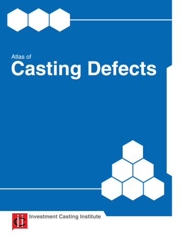
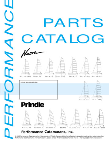
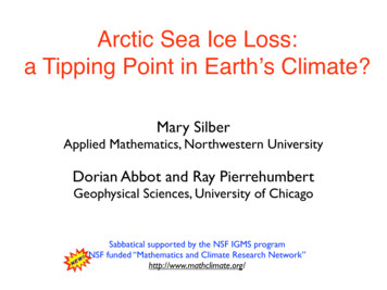
too fast gelling speed usually results in worse slurry fluidity, causing it difficulty to fill the wholecavity.The catalyst can be either acid (to change pH value towards 1.0) or alkaline (to change pHvalue towards 6.0). The popular acid catalyst includes H2SO4, HCl, H 3PO4. The alkaline catalystincludes NaOH, Ca(OH)2, MgO, CaO, Mg(OH)2, Na 2CO3 and various organic materials. In ourstudy, we use alkaline catalyst.2.4 Separating AgentSeparating agent is needed for investment casting with ice patterns. The reason is that theslurry contains alcohol and water. The alcohol and water will interact with the ice patternsurface. The decomposition process releases heat which causes more decomposition. As a result,the ice pattern surface will be seriously damaged. The separating agent material must satisfy thefollowing requirements:§ Not soluble with water or alcohol.§ Not reacts with water or alcohol.§ Not freeze at sub-zero temperatures.§ Have good coating property on ice surface at low temperatures.§ Non-toxic and no pollution.In our experiment, we use the mixture of silicate oil and kerosene (1:1 ratio). Beforecoating the ice patterns, the separating agent is cooled to the ice pattern temperature.3. INVESTMENT CASTINGEXPERIMENTSSince the following study isfocused on the process of investmentcasting with ice patterns, the icepatterns can be built either by rapidfreeze prototyping or by traditionalmolding method. In order to evaluatethe casting accuracy, the ice patternshould be simple and easy to measure.In this study, we use a cylindrical icepattern made by traditional moldingmethod. The ice pattern is made with asteel mold with a diameter of 30 mm,as shown in Figure 2. Separating agentis coated on the outer and interiorcylinders before injecting water to helpremove the ice pattern after freezing.01-base02-outer cylinder 03-interior cylinder04-sealing ring 05-fixing axleFigure 2. Steel mold for making cylindrical ice patterns3.1 Ceramic Shell MakingThe steps to make a ceramic shell with an ice pattern are as follows:§ Prepare binder with composition listed in Table 1 and mix ceramic powder materialwith mixing ratio given in Table 2.69
§§§§§§§Measure 20 ml binder, 60 g powder mixture, and 3 ml catalyst. Put them separately in alow-temperature environment of –5 C and allow them to cool down.Make cylindrical ice pattern with steel mold shown in Figure 2 and measure thediameter of the obtained ice pattern.Cover the ice pattern with the outer cylinder (part 02 in Figure 2) and coat the interiorsurface of the outer cylinder with separating agent.Mix binder with powder and then add the catalyst.When the slurry is about to gel, inject the slurry into the outer cylinder and keepvibrating to let the air in the slurry out.After the slurry has completely set, take the mold out and put in room-temperatureenvironment to melt the ice pattern and drain the water.Take the ceramic shell out of the outer cylinder and measure the interior diameter of theshell cavity and observe the surface quality.The shell making experiments have shown that the shell dimensions keep changing withtime at room temperature, as given in Table 3.Table 3. Ceramic shell diameter (mm) vs. time at room temperatureSamplesOriginal size24 hours 48 hours 72 hours(after 60329.7629.6029.5629.52429.7629.6229.5829.54It can be seen from Table 3 that the shells all have the largest diameters originally and thenthe sizes become smaller and smaller at room temperature. The sizes change most significantlyduring the first 24 hours. The sizes vary 0.12 0.20 mm during the first 24 hours, 0.04 0.06mm during the second 24 hours, and 0.02 0.04 mm during the third 24 hours. The shrinkage iscaused by the evaporation of the residual water and alcohol in the shell. To make the shelldimension get stable quickly, we select to fire the shell after removing from the mold. Table 4gives the shell diameter variation with time at room temperature. Comparing Table 4 with Table3, we can see that after firing treatment, the shell dimension becomes more stable. The variationin 48 hours is negligible.Table 4. Ceramic shell diameter (mm) vs. time at room temperature with firing treatmentSamplesOriginal sizeFiring 30 min. and48 hours(after demolding) cooled down 7829.803.2 Investment Casting Experimental ResultsThe ceramic shell obtained above still needs to be fired at a higher temperature for a longertime because the firing treatment mentioned above is only for the purpose of keeping shelldimensions stable and the firing treatment is short (only 30 min.) and mostly occurs on the70
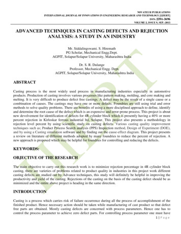
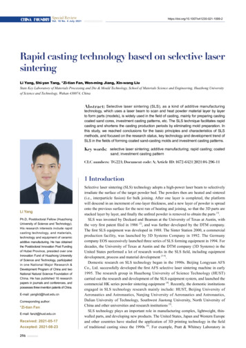
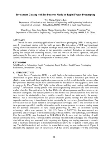
surface region. To make the shell ready for casting, we fire the shell at 600 C for 2 hours andkeep the temperature at 200 C when casting. There are three reasons for firing the green shellbefore casting[8]: A) to remove residual pattern material and solvents remaining in the ceramicshell, B) to sinter the structure of the ceramic, and C) to present the shell for casting at apredetermined and consistent temperature to reduce the temperature difference between moltenmetal and shell.After firing, the shells are used for casting. In this study, we used casting aluminum ZL 103as the cast material. Casting temperature is set at 638 C. The obtained metal part (cylinder) ismeasure and compared with the initial ice pattern and ceramic shell. Table 5 lists the results of 7test samples. The dimensional variation due to firing (600 C for 2 hours) is 0.026% in average.The dimensional variation between ceramic shells and cast metal parts is 2.26% in average. Andthe dimensional variation between original ice patterns and cast metal parts is 2.84% in average,with maximum and minimum variation of 4.01% and 2.14% respectively.Samples1234567Table 5. Dimensional comparison of investment casting with ice patternsRelative errorRelative errorCast PartShell Diameter Shell DiameterDiameter compared with compared withafter firingbefore firingice patternceramic nt casting with ice patterns made by rapid freeze prototyping is the same as theprocess described above. Figure 3 shows the ice pattern made by rapid freeze prototyping, theobtained ceramic shell, and the cast metal part.(a) Ice pattern made by RFP(b) Ceramic shell(c) Cast metal partFigure 3. Investment casting with ice patterns made by RFP71
4. CONCLUSIONInvestment casting with ice patterns has some different requirements from regularinvestment casting (with wax pattern) both in the material and the operating process. It requiresthe binder not to freeze at sub-zero temperatures and not to react with ice. Making ceramic shellfrom ice patterns needs low temperature to avoid ice pattern melting. The study hasdemonstrated the feasibility of making metal parts by investment casting with ice parts made byrapid freeze prototyping. Binder materials satisfying the special requirement has been developed.Further study will be focused on developing better binder material that can result in betterceramic shell accuracy and dimensional stability.ACKNOWLEDGEMENTThe authors at Tsinghua University gratefully acknowledge the support of the NationalNatural Science Foundation of China.REFERENCES1) Zhang, W., Leu, M. C., Ji, Z., and Yan, Y. N., “Rapid Freezing Prototyping with Water,”Materials and Design, Vol. 20, pp. 139-145, June 1999.2) Zhang, W., Leu, M. C., Sui, G. H., and Ji, Z., “An Experimental and Analytical Study of IcePart Fabrication with Rapid Freeze Prototyping,” Proceedings of the 10th Annual SolidFreeform Fabrication Symposium, University of Texas at Austin, Austin, TX, pp. 591-598,August 1999.3) Gavrilin, I. V., “Ice pattern casting,” Liteinoe Proizvodstvo No. 9 Sept. 1994 Mezhdunarodnaya Kniga, Moscow, Russia, pp.14-15, 1994.4) Yodice, A., “Freeze Process Cuts Casting Costs,” Advanced Materials & Processes, Vol.155, No. 4, pp.35-37, 1999.5) Yodice, A., INVESTMENT CASTING PROCESS, U.S.A Patent, 5,072,770, Dec. 17, 1991.6) Yodice, A., “Freeze Cast Process Ready for Licensing,” INCAST, p19-20, Dec 1998.7) Wu, Xiaolu. The study of Investment Precision Casting based on ice rapid prototype, Masterthesis, Tsinghua University, Beijing, China, June 1998.8) Beeley, P. R. and Smart, R. F., Investment Casting, The Institute of Materials, London, 1995.72
these processes provided valuable information on the low-temperature investment casting slurry for the potential application of rapid freeze prototyping. In 1991, an investment casting technology, which was patented in 1991 (US Patent # 5,072,770), has demonstrated the possibility and advantages of investment casting with ice patterns.