Transcription
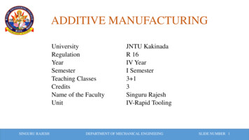
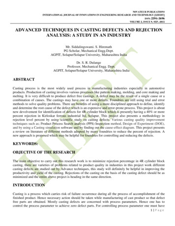
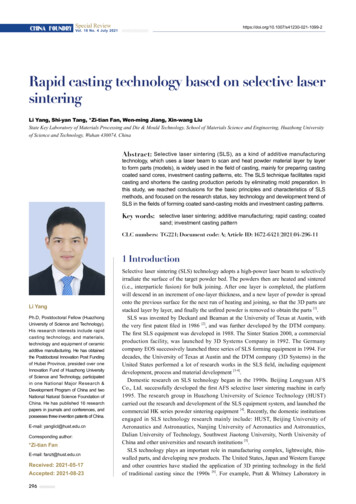
Investment Casting – Rapid Tooling Approach1SIVADASAN M, 2N. K. SINGH ,3ANOOP KUMAR SOODNational Institute of Foundry Forge Technology Ranchi 834 003,Jharkhand,IndiaE-mail: msdn100@gmail.comAbstract— Investment casting is synonym with producing precision components and investment casters usually take upthe order if the volume is huge enough. This is due to high and unjustifiable tooling cost and long lead times associatedwith the development of metal moulds for producing wax (sacrificial) patterns for customized single casting or smallquantity production. One of the feasible solutions is opt rapid tooling. In so- called rapid investment casting the most criticalprocess will be building the investment shell and protecting it from thermal crack. This work investigates the shell crack andcounter. In this work pattern are modeled on rapid prototyping machine. During the ceramic shell preparation cracking isreported. Hence a remedy is explored as to control the thermal expansion of the pattern build material-acrylonitrilebutadiene styrene (ABS) by using different build styles. Thermal expansion of five distinct styled ABS rapid samples weretested on Dilatometer. The investigation indicates the possibility of 63% reduction in thermal expansion of the pattern,which is very very encouraging.Keywords: Investment Casting (IC), Rapid Prototyping (RP), Rapid Tooling (RT), Precision Castings, Fused DepositionModeling (FDM), Acrylonitrile Butadiene Styrene (ABS),thermal expansion, Percentage Linear Change(PLC),Dilatometer.1. IntroductionThe Investment Castings (IC) was knownto our ancestors as an art of making toys and toolsdate back to four thousand years even. IC is synonymwith precision castings [ 1,2]and has several criticalstages of production. Fig.1( i & ii ) is pictorialrepresentation of the major stages ( a to j) involved.People engaged with IC understand the enormouscalendar time they elapse to arrive at the first casting– it runs to months. In this, majority of the time isspent on developingthe Tooling successfully .Customarily by default the prototype development ortooling for wax pattern is costly and lengthy henceinvestment casters usually take up the order only ifthe volume is huge enough.At the same time reduction of productdevelopment cycle time is a major concern inindustries to remain competitive in the market placeand hence focus has shifted from traditional productdevelopment technology to rapid fabricationtechniques like rapid prototyping (RP) . RP process iscapable of building part of any complicated geometryin least possible time without incurring extra cost dueto absence of tooling. Another advantage with RP isFig.1(i)a&b Design & development of the mould for wax pattern isthe critical delay factor in ICFig .1(ii)International Journal of Mechanical and Industrial Engineering (IJMIE), ISSN No. 2231 –6477, Vol-1, Issue-4, 201299
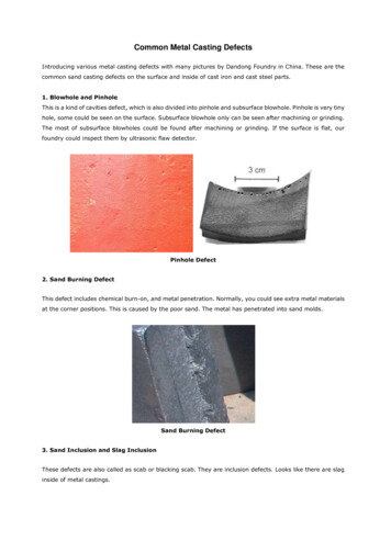
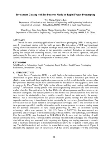
Innovating Investment Casting – Rapid Tooling Approach-the scope of unlimited –no –cost design iterations ondigital data. RP offers several other benefits.[ 3,4]Although RP is an efficient technology fullscale application and exploitation has not gainedmuch attention because of various reasons, primarilycompatibility of presently available materials with RPmachines and unavailability of authentic datarequired by metal casters. When RP & IC are linkedsuitably this may lead us to exploit full potential ofboth besides countering disadvantages. [5,6,7,8,9,10].But there are four principal issues which theauthors have experienced when experimented RPwith Investment Casting .i) Residue deposit after shell firing.ii) Pattern contraction/ expansion in x, y & z buildaxes.iii) Shell Cracking during firing.iv) Ra. value on pattern to command required Ra. onthe casting.The authors believe above issues are to beaddressed well before we offer RP to Investmentcasters. Though partial, a few researchers[11] claimsuccess, no published work known to the authorshas successfully addressed all above problems andauthors have taken up the work of resolving theseissues to popularize the RP in industry and academiaas well. Our previous work [12] reports suitability ofABS pattern for preparing the IC shell. Present workfocuses on expending /firing the pattern and issuesassociated with it. The experiment is done in twoparts. First part - a set of acrylonitrile butadienestyrene (ABS) patterns are generated onSTRATASYS’ fused deposition modeling (FDM) RPmachine. The patterns are converted into castingsthough IC route and shell cracking tendencyobserved. In the second part five test patterns of size12ømm*12mm are generated on FDM machinesemploying different build styles to minimize theseverity of thermal expansion and their respectivethermal expansion values are estimated on the OrtonDilatometer model DIL2016.Fig. 2 Schematic description of FDM processTable.1 FDM process parametersSl12345SettingsRaster AngleAir GapSlice ThicknessRaster widthEnvelop TemperatureValue45 degree0.0 mm0.4064mm0.4064mm80 Cart I ( ABS patterns are generated and convertedinto castings through IC route.)Patterns are prepared in ABS Fig.3 (i).Pattern Tree is made Fig.3 (ii & iii) . Shell isprepared Fig.3(iv) with subsequent dipping andstucco and fired. The mould is poured in planecarbon steel and components are made , as - cast asshown in Fig.3 (v)2. ProcedurePattern PreparationThe 3D (Three dimensional) CAD modelsare modeled in CATIATM software and imported toFDM Vantage SE Machine in STL format. Here theprocess parameters are set as per the values given inTable 1 and parts are fabricated using ABS as a builtmaterial. For material deposition FDM uses twonozzles, one for model material deposition and otherfor support material deposition. These two nozzleswork alternately to each other. Fig. 2 provides theschematic description of FDM machine partfabrication methodology. A few parts are generatedwith solid (fills the part interior completely) and fewparts are generated with sparse (honeycomb typeinternal structure) interior fill style.Fig. 3 (i)Fig. 3 (ii)Fig.3(iii)International Journal of Mechanical and Industrial Engineering (IJMIE), ISSN No. 2231 –6477, Vol-1, Issue-4, 2012100
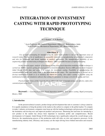
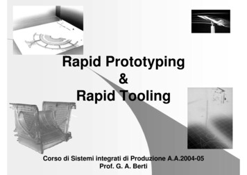
Innovating Investment Casting – Rapid Tooling 64SparsefillairgapnaRastertorasterair art II( ABS test samples are generated on FDMand tested on Dilatometer)Five test samples Fig.4(i&ii) of size (12 ømm*12mm) are modeled on FDM machine for testingthe thermal expansion. Different parameters and buildstyles are used to generate distinct internal webstructure in the sample. A few build parameters aredisplayed for the information of the enthusiasticreaders as in the Table.2.Fig.4(i)Orton Dilatometer Fig.5 is a versatile pieceof equipment designed to measure the thermalExpansion/Percentage Linear Dimensional Change ofany solid material( ceramics,glass,metal,polymers etc)as a function of temperature.Standard Orton Dilatometer [13 ]is a digital,horizontal, single sample bench top system comprisedof a furnace with silicon carbide heating element (1600C), fused quarts sample holder system,thermocouple , sample displacementsystem(consisting of Probe Rod, Linear VariableDimensional Transducer and counter -Fig.4(ii)-weighed pulley.),Control board for furnace and dataacquisition with Orton software. Sample in the holderis pushed into furnace and heated from roomtemperature to 100 C. the expansion of the sample isprobed and transmitted to LVDT, it generates signalcorresponding to the change in sample length andcontinuously sends that signal to the Orton BoardComputer along with the thermocouple output. As aresult, the PLC(percentage linear change)Vs.International Journal of Mechanical and Industrial Engineering (IJMIE), ISSN No. 2231 –6477, Vol-1, Issue-4, 2012101
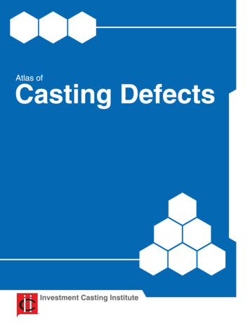
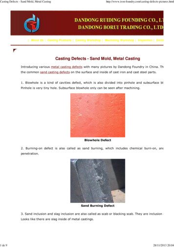
Innovating Investment Casting – Rapid Tooling Approachtemperature of the test sample is obtained from thedisplay continuously. The readings against eachsample is recorded as shown in the Table.3.Let us now see the Dilatometer output. Fig.7is the PLC Vs Temperature graph generated forsample R1. One can read the softening temp and thecorresponding percentage linear expansion from thegraph as 81 C & 0.363 respectively. Similar graphsare generated for other four samples. In this context itis important to understand the thermal expansion ofthe ceramic shell also. The ceramic shell will alsoexpand but the thermal expansion of ceramic shellbelow the softening temperature of ABS ( i.e below80 C) is negligible. Hence the expansion of ABS willbe the only deciding factor of shell cracking. Theresult got from the dilatometer for test samples ofvaried internal web structures indicate that we couldattain more than fifty percentage reduction ( 63%)in thermal expansion from sample solid build R1. tosparse build sample R5.,controlling the sparse air gap,and it is a very encouraging result which might helpus to control the shell cracking to nil.Fig.7Fig. 5Table.33. ResultUnlike other casting processes IC involvespattern investing (burying) in the ceramics andexpending (firing) it out later. These two factorshence decide the suitability of ABS replacing wax.Author’s previous work had investigated and reportedthe first factor and in this work it is found that thereare complications in the second factor ie. in firing, in%linearSofteChange,PLCning L/Lo 28690.290R412.2230700.195R512.2227690.133which shells are found with cracks.Fig.6. This may bedue to the differential thermal expansions of ABSused for the pattern and the ceramic used for theinvestment shell build up.SampleInitialLengthLo mmStartTemp,oC4. DiscussionABS softening starts in the temperaturerange of 70C to 80C and then collapsing impends.Hence the researchers working on this issue ofcontrolling the shell cracking tendencies, ininvestment casting, need to bother the thermalproperties of the ceramic shell within this range only.It is clear that as the thermal expansion of theceramic shell is negligible bellow the softeningtemperature (80C) of ABS, the critical factor to becontrolled is the thermal expansion of ABS. Ourinvestigation proves this control is possible throughthe manipulation of ABS patterns build styles.Fig.6International Journal of Mechanical and Industrial Engineering (IJMIE), ISSN No. 2231 –6477, Vol-1, Issue-4, 2012102
Innovating Investment Casting – Rapid Tooling Approach[6] Peter D Hilton,Paul F.Jacobs. “Rapid Tooling Technologiesand Industrial Applications”, Marcel Dekker,Inc,New York 2000 pg 1-13.5. Conclusion and scope for further research.The study is a part of our investigation tointegrate RP with IC and itexplored theapplicability of FDM generatedABS patternsuitability for IC . This work focused on thermalcracking tendency of IC shell. The results indicate ameans to control the cracking tendency of IC shells.However, before commercialize the process,continued research is required to establish the scalefactor for ABS in xyz directions and to establish asuitable post finishing operation on the ABS todeliver thesurface qualities, precision castersdemand. The ABS used on FDM machine beingproprietary there is an urgent need for documentingits coefficient of thermal expansionto win theconfidence of Cast Houses before FDM based RTis transferred to its potential users.[7].[8]Paul Blake,Colin Gouldsen “Investment Casting UsingFDM/ABS Rapid Prototype Patterns”, 2000.C. W. Lee, C. K. Chua ,C. M. Cheah,L. H. Tan , C. Feng.“Rapid investment casting: direct and indirect approaches viafused deposition modeling”.Int J Adv Manuf Technol (2004)23: 93–109.[9] Mohd. Hasbullah Idris and Safian Sharif, Wan Sharuzi WanHarun,Universiti Teknologi Malaysia.“Evaluation of ABSPatterns Produced from FDM for Investment CastingProcess” APIEMS2008- Procee. 9th Asia Pasafic IE & MgmtSystem Conf- 2008.[10] Graham Troman, Developments in RapidProfessional Engg Publishing, London -2003.[11]. W.L. YaoU, Ming C. Leu‘Analysis and design of internalweb structure of laser stereolithography patterns forinvestment casting’ Materials and Design 21 2000 101- 109.AcknoeledgementThe authors wish to thank Director NationalInstitute of Foundry Forge Technology, Ranchi forthe encouragement in doing this work and oweindebtedness to HoD Deptt. of Foundry Tech and hisWorkshop staff.[12].Sivadasan M, N K Singh, A K Sood,”Use of fused depositionmodeling process for investment Precision casting – a viablerapid tooling.” secondInternational Conference onadvancement in Mechanical engineering in Sept2012,www.worldairco.org under print.[13]. The Edward OrtonDocuments.Rererences[1]Investment Casting Hand Book.InvestmentInstitute.Illinois1968.pg 156-158[2]Investment Casting Edited by Peter R Beeley & Robert .Institute of Metals-1995[3]Anoop Kumar Sood, R.K.Ohdar,S.S. Mahapatra,”Parametricappraisal of mech. property of fused deposition modelingprocessed parts”, Materials and Design 31 (2010) 287-295.Jr. Ceramic Foundation, USA. SaleCasting [4] Kenneth G Cooper,NASA. “Rapid Prototyping TechnologySelection and Application”. Marcel Dekker -2001. Pg- 153.160.[5]Rafiq Noorani “Rapid PrototypingAplication”John Wile ,2006.PrinciplesCasting,andInternational Journal of Mechanical and Industrial Engineering (IJMIE), ISSN No. 2231 –6477, Vol-1, Issue-4, 2012103
Customarily by default the prototype development or tooling for wax pattern is costly and lengthy hence investment casters usually take up the order only if the . Innovating Investment Casting - Rapid Tooling Approach International Journal of Mechanical and Industrial Engineering (IJMIE), ISSN No. 2231 -6477, Vol-1, Issue-4, 2012