Transcription
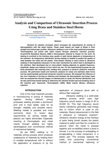
International Academic ResearchJournal of Engineering SciencesVol. no.1 issue no 1, February 2016, Page No.13-33ISSN No: 2414 - 6242 (Print)Analysis and Comparison of Ultrasonic Insertion ProcessUsing Brass and Stainless Steel HornsKamalaesh UKDepartment of Production EngineeringPSG College of Technology, Coimbatore 641004 Indiakamalaeshuk1@gmail.comDr. Elangovan SDepartment of Production EngineeringPSG College of Technology,Coimbatore 641004 IndiaAbstractDemand for plastics increases which increases the requirements for joining ofthermoplastics with the metal inserts. These metal inserts are made of Brass in formstraight and helical gear profiles. Ultrasonic welding is one of the most preferred processes.Thermoplastics are joined with metal inserts through ultrasonic insertion process.Acrylonitrile Butadiene Styrene (ABS) a thermoplastic material is chosen for the work. Asheating is confined to the interface area, quality of weld mainly depends on temperature atthe interface. So temperature distribution during welding is studied to predict the quality ofweld between the metal and the plastic. Visco-elastic heating is most critical to ultrasonicwelding of thermoplastics because it is the main mechanism by which heat is developed atthe interface. Heat developed due to visco-elastic heating depends on applied frequency,amplitude, design and material of horn which we use. For the experimental purpose we usethree parameters like inserting time, holding time, pressure to perform ultrasonic insertionprocess. We performed modal and harmonic analysis for brass and stainless steel hornsand we experimentally performed ultrasonic insertion process. We analyzed the influence oftwo horn materials in forming an effective joint between the thermoplastic and brass insertthen we analyzed the thermal images of inserted parts to study the thermal distribution andwe also performed tensile testing to determine the ultimate tensile load and breaking load ofthe inserted part. Keywords: Thermoplastic (ABS); Metal inserts (Brass); Ultrasonicinsertion.INTRODUCTIONOne of the most important processin manufacturing is joining of materialstogether.Amongdifferentjoiningprocesses welding provides a permanentjoint and is most widely used for itsstrength, reliability and versatile nature.Welding metals is possible and morecommonlydone.Inrecentdaysrequirements for joining metals andplastics are highly demanded. Especiallyinserting of thermoplastic and metalinserts through welding are highlyadvantageous over conventional methodof mechanical fastening.As per AWS, welding is, "Amaterials joining process which producescoalescence of materials by heating themto suitable temperatures with or withoutthe application of pressure or by theapplication of pressure alone with orwithout filler materials"Ultrasonic welding is a solid-statewelding process which uses highfrequency sound waves in range of 20 to20,000 Hz. This high frequency soundwaves (vibrations) generates heat energydue to friction which is used to joinmaterials. Recent advancement in the fieldof ultrasonic is "ultrasonic insertion".Ultrasonic vibration energy at the interfaceof parts being joined causes the plasticmaterial to soften and flow for a fraction ofsecond, when the metal is pressedtogether and re-solidified where a bond isformed. It is the process of embedding orencapsulating a metal component in aplastic part. This process replaces thecostly, time consuming, conventionalmethod of mechanical fastening of
14International Academic Research Journal of Engineering Sciencesthermoplastic with metal component. Thethermoplastic part to be assembled isplaced together with the brass insert,metal on top of the plastic part, in asupportive nest called a fixture. A horn isbrought into contact with the upper metalinsert. A controlled pressure is applied tothe parts using horn against the fixture.The horn vibrates vertically 20,000(20 kHz) or 40,000 (40 kHz) times persecond, at distances measured inthousandths of an inch (microns), for apredetermined amount of time called weldtime. This vibratory mechanical energy isdirected to limited points of contactbetween the two parts. The mechanicalvibrations are transmitted through thethermoplastic materials to the jointinterface to create frictional heat. Whenthe temperature at the joint interfacereaches the melting point, plastic meltsand flows, and the vibration is stopped.This allows the melted plastic to begincooling. The clamping force is maintainedfor a predetermined amount of time toallow the parts to fuse as the meltedplastic cools and solidifies. This is knownas hold time. Once the melted plastic hassolidified, the clamping force is removedand the horn is retracted. The plastic partis now joined with the metal insert andthen it is removed from the fixture as onepart.A. Ultrasonic inserting processUltrasonic Insertion is the assemblyprocess of embedding a metal componentin a thermoplastic part. A hole is premolded into the thermoplastic part slightlysmaller than the O.D. of the insert it is toreceive. As ultrasonic energy is applied tothe insert, frictional heat is generated dueto the insert vibrating against the plastic.The plastic melts, permitting the insert tobe driven into place. The insert issurrounded by molten plastic, which flowsaround the knurls, flutes, and undercutson the O.D. of the insert.FebruaryB. Ultrasonic inserting methods1. The horn can touch the insert,driving it into the plastic part.2. The horn can touch the plastic part,driving it over the insert.C. Process parameter guidelines.The following basic guidelines forultrasonic insertion should be taken intoconsiderationwhendevelopinganultrasonic insertion process: Low to medium amplitude - thetotal gain of the horn/boostercombination should be between1.5 to 2.5. Low to medium pressure - 100 to280 kPa with pressure increasedaccordingly for large or multipleinserts. Pre trigger should be active. Slow down speed of the carriageassembly, to allow melting to occurand to prevent cold pressing theinsert in place. Rigid fixing providing amplesupport during welding. After seating, the top of the insertshould be flush or slightly abovethe surface of the part formaximum pullout strength andtorque resistance.D. PlasticsPlastics are based on polymersand they are created by bondingmonomers together.A monomer is a smallmolecule that combines chemically toother monomers to form a polymer.Example: An ethylene monomerforms a long chain monomer due toindividual ethylene monomers joinedtogether. This produces the polymerpolyehtylene.E. Advantages of ultrasonic insertingprocessUltrasonic insertion offers severaladvantages over the other insert assemblytechniques including
2016Kamalaesh UK, Dr. Elangovan SShort cycle time-typically less thanone second. Reduced molding cycle times. Multiple inserts can be driven atone time. Idealforautomated,highproduction operations. Repeatability, consistency, andcontrol over the process. Moreconsistentresultsascompared with direct thermalprocesses.F. Applications Instrument panels Door panels Electronic panels Steering wheels Engine components Door handles and house holddevices LITERATURE REVIEWMore than 20 national andinternational journals from 1994 to 2014regarding joining of plastics and metalshave been studied. Some of them arepresented below. Rooparani et al [1],(2007),discussed about the modal andharmonic analysis of various horn profilessuch as catenoidal, stepped, cylindrical,Gaussian and Bezier and analyzed theamplitude gain at output end and VonMises stresses developed on the horn. Tovalidate the simulated results five differenthorns are made of aluminum alloy andexperiments are conducted. StandardABS plastic parts are welded and thetemperature developed at the joint isrecorded using sensors and Dataacquisition system. It was observed thathighest temperature at the interface isobtained when using Bezier horn andwelded joint had higher strength ascompared to other horn profiles. Thedifference in the simulated and measuredtemperature value for stepped horn is 50%and Bezier horn is 40%. It was observedby tensile testing that weld strength is15increased with increase in interfacetemperature. The stepped horn had only75% energy utilization as compared to85% of the Bezier horn. The horns likeCylindrical, Gaussian and Catenoidalwhich are found to have an amplitude gainof less than or equal to two can be usedfor applications involving amorphouspolymers and moderately strong joints.The stepped and Bezier profile hornswhich are having an amplitude gain ofthree can be used for applicationsinvolving semi-crystalline polymers and forwelding components in the far field. Butamong the two Bezier is preferredbecause of low Von Mises stress in thenodal region and better energy utilization.It is observed that Bezier horn profile ishaving maximum displacement followedby the stepped horn and the catenoidalhorn. As the end diameters of the hornsare same, it is evident that the amplitudegain depends on the horn profile.In the work of Ramani, (2004),adhesion between low-carbon-steel andinjection-moldedpoly-carbonatewasinvestigated. They revealed that the fastcooling leads to the development of higherresidual stresses and they found thatextent of residual stresses can be greatlyreduced by proper design of the injectionover-molding process.In the work of Sasaki et al, (2006),adhesion of injection over-molded polyamide 6 (PA6) thermoplastic polymer andstainless steel plates pre-coated withtriazinetrithiolpolymer(TTP)wasinvestigated. Adhesion strength betweenPA6 and the pre-coated 417 stainlesssteel plates was found to be relativelylarge. They also revealed the formation ofiron and the stainless steel. Furthermore,formation of chemical bonds throughnucleo-philic substitution terminal aminogroups in PA6 was observed.Laput [10], (2012), they discussedabout adhesives for assembly of hard tobond plastics and found that polyolefin
16International Academic Research Journal of Engineering Sciencesplastics are the most common type of hardto bond plastics due to their low surfaceenergy.Bolt [11], (2014), performed anexperimental study to examine theapplication of displacement controlledUltrasonic Plastic Welding (UPW) duringcreation of joints between aluminium orsteel and carbon fiber reinforcedpolyamide 6 [CFR-PA6].Dunn [12], (2012), performedwelding in resin by catalytic bondexchange reaction and found that longerholding at higher temperature will yieldbetter recovery of properties and it issuitable to repair polymer structure andrecyclethethermosetwasteinengineering applications.Menon [13], (2011), The mainambition was to study the bondingcharacteristic between stainless steel andsilane layer. Silanes are the most commoncoupling agent for metal to plasticbonding. They found that characterizationof interfacial zone between stainless steelinserts and silane depends more onvarious properties of stainless steel andsilane solutions.Eckel [14], (2001), This reportstudies the feasibility of a new techniquewhoseadvantagesovercomethedrawbacks of using mechanical fastenersor chemical adhesives for joiningthermoset (TS) composites. This newtechnique is also called as fusion bondingwhere two thermosets are joined in shortertime.Grewells [15], (1994), This paperprovides general introduction to welding ofplastics and its developments, followed bydiscussion about ultrasonic welding andalso about other different types of welding.Grujicic [16], (2007), found amethod of joining a thermoplastic materialto a thermoset material and a resultantthermoplastic-thermosetcompositeformed from such method are studied. Atleast one of the thermoplastic material andFebruarythe thermoset material includes particlessulpho glass or sulpho-phosphate glassparticles that melt, when the thermoplasticmaterial and the thermoset material areheated during the joining operation. Theparticles further produce a solid bondbetween the materials after the particleshave been solidified during cooling, afterthe joining operation and finally is bonding technique is alsoknown as a fast welding technique wherein the order of seconds an effective joint iscreated by means of fusion bonding ofthermoplastics.This is a result of visco-elasticheating, interfacial friction induced byperpendicular ultrasonic vibrations of asonotrode which is pressed over thewelding overlap. The potential ofapplication of this welding technique lies inreduction of joining times in assembly line,while maintaining high joint strengths withlow variation and also they found that thewelding strength for hybrid welds washigher when compared to the non-hybridweld for same input.In this paper they have comparedselected properties of plastics, metals andthe results determine applications ofjoining of moulded pieces from plasticsand metal element. Metal inserts areapplied for the improvement of somestrength properties in mould pieces fromplastics. From this they revealed thatplastics have several times greatercoefficient of heat expansion andcontraction is several times greater thanthat of metals in the range of temperaturesfor transformation of materials and forchilling of mould pieces.Pereira [17], (2012), This paperdescribes about the various joiningtechnologies that are used in aerospaceapplications such as fusion bonding,ultrasonic welding, resistance welding,induction welding and many more. Finally
2016Kamalaesh UK, Dr. Elangovan Sthey found out that each method waseffective in different applications indifferent fields and has its own advantagesand disadvantages.Nakazawa [18], (1994), describesabout the mechanism of adhesion ofepoxy resin to cold rolled steel, galvanizedsteel and galvannealed steel and also theproperties were compared using tensiletest, shear test, impact test. They foundthat galvanized steel adhesive joints areinferior to other two steels joints.Raos [20], (2002), This paperdescribes about the various process ofjoining plastics and composites and alsoabout welding evaluations and testing.PROBLEM IDENTIFICATION ANDOBJECTIVEA. Problem identification Conventional method of mechanicalfastening (hammering) of metal insertinto a plastic part provides very lowtorsional resistance and tensilestrength. Weldqualitybetweenthethermoplastic part and metal insertmainly depends on temperature at theinterface of metal and thermoplastic. Proper horn design and material usedfor horn fabrication plays a vital role intheweldpropertiesandperformance(quality) of welding inultrasonic insertion process. Animproper horn design will not developsufficient temperature at the plasticmetal interface for the plastic toplasticize and flow. Tensile strength study and thermaldistribution study of inserting processis very important to predict the qualityof insertion. The major problem faced by theindustries with respect to ultrasonicinserting process is poor insertingquality of metal into plastic and lowweld strength between the metal insertand thermoplastic.17B. Objectives To understand the mechanism ofultrasonic Insertion and to study thevariousprocessparametersinfluencing the ultrasonic insertingprocess. To perform modal and harmonicanalysis for different designs ofbrass and stainless steel horns. To analyze the deformation fordifferent horn designs and fordifferent horn materials duringultrasonic inserting process usingANSYS software. To record thermal images andanalyze the thermal distribution inthe inserted component. To perform tensile testing todetermine the ultimate tensile loadand breaking load. To join thermoplastics with metalinserts through ultrasonic insertionprocess. To produce a hybrid product whichovercomes the conventional methodof using mechanical fastening to joina metal insert with thermoplastics.EXPERIMENTAL PROCEDUREA. Experimental procedureSoftwares used, Pro Engineer ANSYS Mechanical APDL 14.0 Win Tensile CATIA V5R17 Moldflow Plastics Insight 3.1Materials used, Thermoplastic (ABS) Metal Insert(Brass)Machines/Instruments used, Ultrasonic plastic welding machine(1500 W, 20 kHz) manufactured byM/s National Indosonic Tensile Testing Machine (Model:TKG-EC-10kN) (ZWICK 1484) Thermal ImagerStandardized samples were used in allthe experiments of ultrasonic insertion. A
18International Academic Research Journal of Engineering SciencesZWICK 1484 tensile tester was used tomeasure the strengths of the jointsbetween insert and the plastic material.Test procedures according to ASTMstandard D638-97 (Standard Test Methodfor Tensile properties of plastics) wereused.When screws or bolts are threadeddirectly into plastic components, failurescan occur due to stripped threads orplastic creep. In situations where jointstrength and the ability to assemble anddisassemble without degradation ofcomponents is required, threaded insertsprovide a serviceable component whichsatisfies the above needs.Modal and harmonic analysis of fourdifferent horns were performed. We keptthe length of horn as constant anddesigned four different horns by varyingthe taper angle and the stepped length outof which three models turned out to be afailure theoretically. The fourth model wassuccessful after analysis using thesoftware where the frequency andamplitude were both in acceptable range.When the experiment was performedpractically, the brass horn could not insertthe metal insert completely insidethermoplastic part, the metal insert wasinserted into the thermoplastic partiallyand hence practically turned out to be afailure too. Here are the parameters forthree trials of ultrasonic insertion usingbrass horn. Trial 1Inserting time: 2 secHolding time: 2.5Pressure: 3bar Trial 2Inserting time: 3 secHolding time: 3.5Pressure: 3bar Trial 3Inserting time: 3 secHolding time: 3.5Pressure: 4barFebruaryThe failure of ultrasonic insertionusing brass horn is due to change inproperties due to alloying elementspresent in brass which makes the brassmaterial incapable to efficiently transmitthe vibrations. Since brass horn could notperform ultrasonic insertion we use horn ofdifferent material to perform the insertion.Stainless steel horn is chosen to performthe analysis, insertion process and hencethe results are compared with that doneusing brass horn. Modal and harmonicanalysis of a stainless horn is made usingAnsys software and the theoretical resultswere successful. Then the ultrasonicinsertion is done using stainless steel hornwhich turned out to be successful. Here isthe parameter for ultrasonic insertionusing stainless steel horn. Trial 1Inserting time : 3 secHolding time : 3.5Pressure: 4barB. TestingThen the two tests were performed1. Tensile testing using tensile testingmachine2. Thermal distribution analysis usingthermal imager Open the Win Tensile software andcreate a new file.Enter the header details andspecimendetailslikewidth,thickness ,load , distance betweengrips etc and give okThe given component is loaded inthe tensile testing machine usingspecially designed fixtureA M10 bolt is inserted inside theinsert and the tightenedThen the machine is on and givethe command "yes" to go onlineand then press" tear load"See when the display in thecomputer shows zeroThen go to parameter selectionand then perform the test
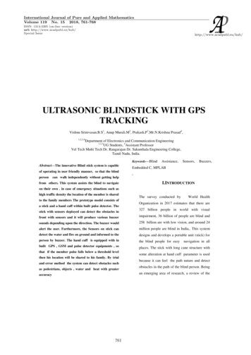
2016Kamalaesh UK, Dr. Elangovan SNow browse the file and print therequired graphs and store them inwordD. Specimen detailsSpecimen width: 135.40Specimen thickness : 3.14Distance between grips : 225E. Test conditions Load at yield Elongation at yield Yield stress Elongation at break Load at break Percentage elongation Reduction in cross section area Proof stressF. Thermal distribution analysisUsing thermal imager the value ofheat generated on the interface of themetal insert and thermoplastic material isrecorded as thermal images. This value iscompared with the theoretical value,Q (W * ² * È)/2 Q average power dissipated W 2*3.14*f f applied frequency maximum strain È loss modulus Q (2*3.14*19032*(44.4*10 /26*10 ³)² *0.42*10 )/2Q 73232327.35 J/m³ Initial gauge length 232 mm Final gauge length 250.69 mm Initial width 135.39 mm Final width 135.39 Initial thickness 3.14 mm Final thickness 3.14 mm Peak load 5.225 kN Maximum crosshead travel 8.23 mm Tensile strength 12.29 N/mm² Load at yield 4.208 kN Cross head travel at yield 7.13 mm Yield stress 9.90 N/mm² Load at break 0.086 kN Cross head travel at break 18.39mm % Elongation19 8.06%The peak load is 5.225 kN which is theultimate load which the component (insertwelded with plastic) can withstand beforethe material at the interface starts yielding.The load at break is 0.086 kN which is theload at which the insert completely comesout of the plastic part. Hence the plasticpart with metal insert can withstand acomparable amount load before failurewhich is achieved by a successful weldedjoint between the plastic and the metal. Emissivity 0.95 Background temperature 22ºC Image range 34.3ºC to 112.0ºC Average temperature 35.8ºC Temperatureatplastic-metalinterface 93.5ºCTemperature at plastic-metal interfaceof the component is 95.7ºC which isapproximately closer to 105ºC where105ºC is the approximate (ABS beingamorphous has no true melting point)temperature required temperature for theplastic to plasticize which is required forthe plastic to flow and fill the grooves andflutes of the insert completely without anyair gaps by which a successful weldedjoint is achieved on cooling.CONCLUSIONSA detailed process study is done onUltrasonic plastic welding and insertingprocess and its guidelines.Carried out a study on the specification ofthe system.Modal and Harmonic analysis of differenthorns of two different materials (Brass andStainless steel) have been performed.Ultrasonic insertion of metal insert intothermoplastic is performed experimentally.Thermal distribution of the insertionprocess is analyzed by both theoreticaland practical methods using thermalimager.Tensile testing of the component is madeby which ultimate tensile load and
20International Academic Research Journal of Engineering Sciencesbreaking load of the metal insert andthermoplastic is determined. FUTURE SCOPEDesign and fabrication of fixture forholding different inserts.Design and fabrication of horn inStainless steel and Aluminium.Optimization of various insertingprocess parameters.Interpretation of results.REFERENCESK.S. Suresh, M. Roopa Rani, K. Prakasanand R. Rudramoorthy (2007),"Modelingoftemperaturedistribution in ultrasonic welding ofthermoplastics for various jointdesigns", Journal of MaterialsProcessing Technology / 186(2007) 138–146.William D Callister, ―Material science andengineeringǁ, 2007Richard L Little, ―Welding and weldingtechnologyǁ, Tata McGraw-Hill,2011Sidney H Avner, ―Introduction to physicalmetallurgyǁ, Tata McGraw-Hill,2012Ever J Barbero, ―Introduction tocompositematerialsdesignǁ,Taylor & FrancisGroup, 2011Sanjay K Mazumdar, ―Compositemanufacturingǁ, CRC Press .com/patents/US7645642Christine Marotta, Mike william andSnicoleLaput, "Adhesives for theassembly of hard-to-bond plastics".Bolt S, "Ultrasonic plastic welding ofcarbon fiber reinforced polyamide6 to aluminium and steel anexperimental study", 2014.FebruaryKai Yu, Philip Taynton, Wei Zhang, Martin,DunnandJerryHQi1,"Reprocessing and recycling ofthermoset polymers based onbond exchange reaction".Karnan Menon, "Characteristics of Silanebonding to stainless steel", 2011.Stephen H Mcknight, Bruce K Fink,Douglas A Eckel and John WGillespie,"Processingandcharacterization of welded bondsbetweenthermosetandthermoplastic composites", 2001.Grewell D and Benatar A, "Welding ofplastics: Fundamentals and NewDevelopments".Grujicic M A, Sellappan V A, Omara M A,Norbert Seyr B, Marc Erdmanncand Jochenholzleitner C, "Anoverview of the orload-bearingautomotive components", 2007.Anahipereiradacosta,EdsonCocchieriBotelho, Michelle LealiCosta, NilsonEiji Narita and JoseRicardo Tarpani, "A review erospace applications", 2012.Makoto Nakazawa, "Mechanism ofAdhesion of Epoxy Resin to SteelSurface", 1994.ElzbietaKopciuszewskaandStanisławBorkowski, "Joining ofmetal elements with mouldedpieces from plastics".MladenSercer and PeroRaos, "Joining ofPlastics and Composites".
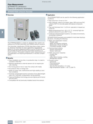
2016Kamalaesh UK, Dr. Elangovan S21Table 1: Tensile Testing Machine SpecificationsDescriptionSl.NoValue1Maximum capacity10KN2Least count displacement0.1 mm3Accuracy of load4Grip separation 1% of indicated load from 4% to 100or load cell capacity25-75 mm5Straining rate1 mm/min to 100 mm/min6PowerSingle phase 220v 50 Hz AC7Motor0.5HpTable 2: Ultrasonic Plastic Welding Machine SpecificationsSl. NoDescriptionValue1MakeUltraweld,National Indosonic, Pune2Input power3Output power1500W4Output frequency20 kHz5Max. Amplitude60 microns6Max. Pressure10 bar7Stroke length230V,50Hz Single phase100 mmFigure 1: Ultrasonic insertion process setup
22International Academic Research Journal of Engineering SciencesFigure 2: Chemical bonding in monomers and polymersFigure 4: Ability to join different materialsFebruary
2016Kamalaesh UK, Dr. Elangovan SFigure 5: MethodologyFigure 6: Ultrasonic Plastic Welding Machine23
24International Academic Research Journal of Engineering SciencesFigure 7: Thermoplastic part modelFigure 8: Thermoplastic part fill timeFigure 9: Thermoplastic part temperature (3D)February
2016Kamalaesh UK, Dr. Elangovan S(a) First design(b). Second design(c) Third design25
26International Academic Research Journal of Engineering Sciences(d) Fourth designFigure 8: Different Brass horn designs - Part modelsFigure 9: Failed modalanalysis for brass horn of first designFigure 10: Failed harmonic analysis for brass horn of first designFebruary
2016Kamalaesh UK, Dr. Elangovan SFigure 11: Failed modalanalysis for brass horn of second designFigure 12: Failed harmonic analysis for brass horn of second designFigure 13: Failed modal analysis for brass horn of third design27
28International Academic Research Journal of Engineering SciencesFebruaryFigure 14:Failed harmonic analysis for brass horn of third designFigure 15: Successful modalanalysis for brass horn of fourth designFigure 16: Successful harmonic analysis for brass horn of fourth design
2016Kamalaesh UK, Dr. Elangovan SFigure 17: Selected brass horn designFigure 18: Tensile Testing Machine (TKG EC 10 - kN)29
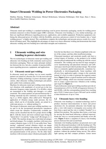
30International Academic Research Journal of Engineering SciencesFigure 19: Stress Vs Elongation graphFebruary
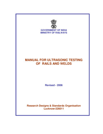
2016Kamalaesh UK, Dr. Elangovan SFigure 20: Load Vs Elongation graph31
32International Academic Research Journal of Engineering SciencesFigure 21: Stress Vs Strain graphFebruary
2016Kamalaesh UK, Dr. Elangovan SFigure 22: Thermal image indicating thermal distribution33
weld between the metal and the plastic. Visco-elastic heating is most critical to ultrasonic welding of thermoplastics because it is the main mechanism by which heat is developed at the interface. Heat developed due to visco-elastic heating depends on applied frequency, amplitude, design and material of horn which we use.