Transcription
PART IIPACS FUNDAMENTALS
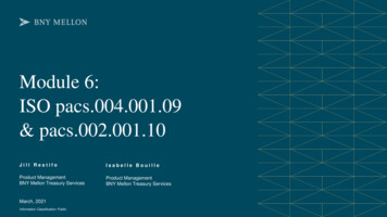
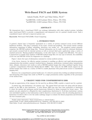
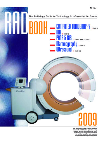
CHAPTER 7Picture Archiving and CommunicationSystem Components and WorkflowThis chapter discusses the basic components of PACS, namely the general architecture, requirements, and functions of the system. The chapter shows how the currentclinical PACS architectures— stand-alone, client/server, and Web-based—illustratethe three prevailing PACS operation concepts. The chapter ends with considerationof teleradiology with regard to PACS and enterprise PACS. Figure 7.1 shows how thetopics of this chapter are positioned with relation to other chapter topics of Part II.7.1PACS COMPONENTSThe major components in PACS consist of an image and data acquisition gateway, aPACS server and archive, and several display workstations (WSs) integrated togetherby digital networks. PACS can be further connected with other healthcare informationsystems by database gateways and communication networks as shown in Figure 7.2.7.1.1Data and Image Acquisition GatewaysPACS acquires images sent from imaging modalities (devices) and related patientdata from the hospital information system (HIS) and the radiology information system(RIS). There are two types of gateways (GW) to the PACS server and archive,the database GW (Fig 7.2, green) for textual data, and the image acquisition GW(Fig. 7.2, yellow) for imaging data. A major task in PACS is to acquire imagesreliably and in a timely manner from each radiological imaging modality via theacquisition GW, and relevant patient data, including study support text informationof the patient, description of the study, and parameters relevant to image acquisitionand processing through the database GW.Image acquisition is a major task in PACS. Because the imaging modality is notunder the control of a single PACS manager, the imaging modalities supplied by manufacturers each have their own DICOM-compliant statements (see Chapter 9). Worse,some older imaging modalities may not even be DICOM compliant. For the manyimaging modalities to connect to a PACS requires many hours of labor-intensivework and the cooperation of modality manufacturers. Next, image acquisition is aslow operation because patients’ examinations are the documents involved in thePACS and Imaging Informatics, Second Edition, by H. K. HuangCopyright 2010 John Wiley & Sons, Inc.219
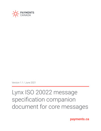
220PICTURE ARCHIVING AND COMMUNICATION SYSTEM COMPONENTS AND WORKFLOWPART II PACS FUNDAMENTALSPACSFundamentalsChapter 7Image/dataAcquisition GatewayChapter 10Communication &NetworkChapter 8PACS Controller &Archive ServerChapter 11DICOM, HL7 andIHEChapter 9DisplayWorkstationChapter 12HIS/RIS/PACSIntegration & ePRChapter 13Figure 7.1 Position of Chapter 7 in the organization of this book. Color codes are usedto highlight components and workflow in chapters of Part II.Generic PACSComponents & Data dalitiesAcquisitionGatewayPACS Server& ArchiveApplicationServersPACSWorkstationsWeb ServersFigure 7.2 PACS basic components (yellow) and data flow (blue: internal; green andred: external between PACS and other information systems); other information systems(light blue). Application servers and Web servers connected to the PACS controller enrichthe PACS infrastructure for other clinical, research, and education applications. HIS:hospital information system; RIS: radiology information system.acquisition process. Inevitably it takes the imaging modality and the radiologicaltechnician considerable time to acquire the necessary data for image reconstructionand to compile a complete image file (Section 4.2). Last, images and patient datagenerated by the modality sometimes contain format information unacceptable for theon-site PACS operation. To address their problem, an acquisition gateway computer,as some manufacturers called it (modality integration unit, MIU), is often placedbetween the imaging modality(s) and the rest of the PACS network to isolate the hostcomputer in the radiological imaging modality from the PACS. Isolation is necessarybecause traditional imaging device computers lack the necessary communication andcoordination software that is standardized within the PACS infrastructure. If, thehost computers do not contain enough intelligence to work with the PACS server
PACS COMPONENTS221to recover various errors, the acquisition gateway computer has three primary tasks:It acquires image data from the radiological imaging device can convert the datafrom the manufacturer specifications to a PACS standard format (header format,byte ordering, and matrix sizes) that is compliant with the DICOM data formats andthen forward the image study to the PACS server or display WSs.Interfaces of two types connect a general-purpose PACS acquisition gateway computer with a radiological imaging modality. With peer-to-peer network interfaces,which use the TCP/IP (Transmission Control Protocol/Internet Protocol) Ethernetprotocol (Chapter 8), image transfers can be initiated either by the radiological imaging modality (a “push” operation) or by the destination PACS acquisition gatewaycomputer (a “pull” operation). The pull mode is advantageous because, if an acquisition gateway computer goes down, images can be queued in the radiological imagingmodality computer until the gateway computer becomes operational again, at whichtime the queued images can be pulled and normal image flow resumed. Providedthat sufficient data buffering is available in the imaging modality computer, the pullmode is the preferred mode of operation because an acquisition computer can beprogrammed to reschedule study transfers if failure occurs (due to itself or the radiological imaging modality). If the designated acquisition gateway computer is down,and a delay in acquisition is not acceptable, images from the examination can beautomatically re-routed to another networked designated backup acquisition gatewaycomputer or a WS.The second interface type is a master-slave device-level connection such as thede facto old industry standard DR-11 W. This parallel-transfer direct-memory accessconnection is a point-to-point board-level interface. Recovery mechanisms againdepend on which machine (acquisition gateway computer or imaging modality) caninitiate a study transfer. If the gateway computer is down, data may be lost. Analternative image acquisition method must be used to acquire these images (e.g.,the technologist manually sends individual images stored in the imaging modalitycomputer after the gateway computer is up again, or the technologist digitizes thedigital hard copy film image). These interface concepts are described in more detailin Chapter 11.There is a way to speed up the image review process after the image examinationis completed. If the imaging modality and the PACS are produced by the samemanufacturer, the image file can be transmitted to the PACS WS immediately afterthe image file is ready for the radiologist to review because PACS will readilyaccept the same manufacturer’s imaging modality. Chapter 10 elaborates more onthe concept and structure of the GW.7.1.2PACS Server and ArchiveImaging examinations along with pertinent patient information from the acquisitiongateway computer, the HIS, and the RIS are sent to the PACS server via the gateways.The PACS server is the engine of the PACS and consists of high-end computersor servers. The PACS server and archive have two major components: a databaseserver and an archive system. Table 7.1 lists some major functions of a PACS server.The archive system can accommodate short-term, long-term, and permanent storage.These components will be explained in details in Chapter 11.
222PICTURE ARCHIVING AND COMMUNICATION SYSTEM COMPONENTS AND WORKFLOWTABLE 7.1 Major functions of the PACS server and archive Receives images from examinations (exams) via acquisition gatewaysExtracts text information describing the received exam from the DICOM image headerUpdates the database management systemDetermines the destination workstations to which newly generated exams are to be forwardedAutomatically retrieves necessary comparison images from historical exams from acache storage or long term library archive systemAutomatically corrects the orientation of computed or digital radiography imagesDetermines optimal contrast and brightness parameters for image displayPerforms image data compression if necessaryPerforms data integrity check if necessaryArchives new exams onto long-term archive libraryDeletes images that have been archived from the acquisition gatewayServices query/retrieve requests from WSs and other PACS controllers in the enterprisePACSInterfaces with PACS application servers7.1.3Display WorkstationsA workstation (WS) includes communication network connection, local database,display, resource management, and processing software. High-quality WSs for radiologists to make primary diagnosis are called diagnostic WS, the others are generallycalled review WS. The fundamental workstation operations are listed in Table 7.2.Until three years ago there were four types of display workstations categorizedby their resolutions: (1) high-resolution (2.5 K 2 K or higher resolution) liquidcrystal display (LCD) for primary diagnosis at the radiology department, (2)medium-resolution (2000 1600 or 1600 1K) LCD for primary diagnosis ofTABLE 7.2 Major functions of PACS workstationsFunctionDescriptionCase preparationAccumulation of all relevant images and information belonging to a patient examinationCase selectionSelection of cases for a given subpopulation through DICOMquery/retrieveImage arrangementTools for arranging and grouping images for easy reviewInterpretationMeasurement tools for facilitating the diagnosisDocumentationTools for image annotation, text, and voice reportsCase presentationTools for a comprehensive case presentation, including 3-Dimage display for a large 3-D file, and fusion imagesImage reconstructionTools for various types of image reconstruction for properdisplay
PACS COMPONENTS223sectional images and at the hospital wards, (3) physician desktop WS (1K to 512)LCD, and (4) hard copy/copying WS for copying images on CD or print on film orpaper. In a stand-alone primary diagnostic WS (Chapter 12), current and historicalimages are stored in local high-speed magnetic disks for fast retrieval. WS also hasaccess to the PACS server database for retrieving longer term historical images ifneeded. Chapter 12 elaborates more on the concept and applications of WS.Over the past three years, as more affordable WS became available in the market,the aforementioned WS categories are no longer applicable. An average-incomeconsumer can purchase a very good PC (personal computer) with 1K LCD displayfor less than US 1000. The classical PACS WS model has evolved to the clientserver model concept. Network computing is now gradually dominating PACS WSdeployment. In this model, the terms thick client, thin client, smart client, and fatclient emerge and become popular on manufacturers’ PACS WS list. A thick clientPACS WS has local storage and many image processing functions and only needsto communicate with the server occasionally; a thin client PACS WS, on the otherhand, has no local storage, very minimal image processing functions, and needs thesupport from the server continuous. In between are the smart client and fat clientWSs. We will discuss this model in Chapter 12 in more detail.7.1.4Application ServersApplication servers (see Fig. 7.2, light blue) are connected to the PACS serverand archive. Through these application servers, PACS data can be filtered to different servers tailored for various applications, for example, Web-based imageviewing server (Chapter 12), radiation therapy ePR server (Chapter 23), image-guidedsurgery ePR server (Chapter 24), CAD server (Chapters 25, 26), and education server(Chapter 28).7.1.5System NetworksA basic function of any computer network is to provide an access path by which endusers (e.g., radiologists and clinicians) at one geographic location can access information (e.g., images and reports) from another location. The required networking datafor system design include location and function of each network node, frequency ofinformation passed between any two nodes, cost for transmission between nodes withvarious speed lines, desired reliability of the communication, and required workflowthroughput. The variables in the design include the network topology, communicationline capacities, and flow assignments.At the local area network level, digital communication in the PACS infrastructuredesign can consist of low-speed Internet (10 Mbits/s signaling rate), medium-speed(100 Mbits/s) or fast (1 Gbit/s) Internet, and high-speed asynchronous transfer modetechnology (ATM, 155–622 Mbits/s and up). In wide area networks, various digitalservice (DS) speeds can be used, which range from DS-0 (56 kbits/s) and DS-1(T1, 1.544 Mbits/s) to DS-3 (45 Mbits/s) and ATM (155–622 Mbits/s). There is atrade-off between transmission speed and cost.The network protocol used should be standard, for example, the TCP/IP (Transmission Control Protocol/Internet Protocol; Chapter 8) and DICOM communicationprotocol (a higher level of TCP/IP). A low-speed network is used to connect the
224PICTURE ARCHIVING AND COMMUNICATION SYSTEM COMPONENTS AND WORKFLOWimaging modalities (devices) to the acquisition gateway computers because the timeconsuming processes of imaging acquisition do not require high-speed connection.Sometimes several segmented local area Internet branches can be used in transferringdata from imaging devices to a GW. Medium- and high-speed networks are used onthe basis of the balance of data throughput requirements and costs. A faster imagenetwork is used between GWs and the PACS server because several GWs may sendlarge image files to the server at the same time. High-speed networks are alwaysused between the PACS server and WSs.Process coordination between tasks running on different computers connected tothe network is an extremely important issue in system networking. The coordinationof processes running either on the same computer or on different computers isaccomplished by using interprocessor communication methods with socket-levelinterfaces to TCP/IP. Commands are exchanged as American Standard Codefor Information Interchange (ASCII) messages to ensure standard encoding ofmessages. Various PACS-related job requests are lined up into the disk residentpriority queues, which are serviced by various computer system DAEMON(agent) processes. The Queue software can have a built-in job scheduler that isprogrammed to retry a job several times by using either a default set of resourcesor alternative resources if a hardware error is detected. This mechanism ensuresthat no jobs will be lost during the complex negotiation for job priority amongprocesses. Communications and networking will be presented in more detail inChapter 8.7.2PACS INFRASTRUCTURE DESIGN CONCEPTThe four major ingredients in the PACS infrastructure design concept are systemstandardization, open architecture and connectivity, reliability, and security.7.2.1Industry StandardsThe first important rule in building a PACS infrastructure is to incorporate as manyindustry de facto standards as possible that are consistent with the overall PACSdesign scheme. The idea is to minimize the need of customized software. Furthermore, using industry standard hardware and software increases the portability of thesystem to other computer platforms. For example, the following industry standards,protocols, computer operating systems, programming languages, workflow profilesshould be used in the PACS infrastructure design: (1) UNIX operating system, (2)WINDOWS NT/XP operating system, (3) C and C programming languages,(4) Java programming language platform (Just Another Vague Acronym), (5) XML(extensible markup language) for data representation and exchange on the WorldWide Web, (6) SQL (structured query language) as the database query language, (7)X WINDOW platform for graphical user interface (GUI), (8) TCP/IP communication protocols, (9) DICOM standard for image data format and communication, (10)HL7 (Health Level 7) for healthcare database information and textual data formatexchange, (11) IHE (Integrating the Healthcare Enterprise) for workflow profiles,and (12) ASCII text representation for message passing.
PACS INFRASTRUCTURE DESIGN CONCEPT225The implications of following these standards and protocols in PACS implementation are several. First, implementation and integration of all future PACS componentsand modules become standardized. Second, system maintenance is easier becausethe concept of operation of each module looks logically similar to that of the others.Moreover, defining the PACS primitive operations serves to minimize the amountof redundant computer code within the PACS system, which in turn makes thecode easier to debug, understand, and search. It is self-evident that using industrialstandard terminology, data format, and communication protocols in PACS designfacilitates system understanding and documentation among all levels of PACS developers. Among all standards, HL7 and DICOM are the most important; the formerallows interfaces between PACS and HIS/RIS, the latter interfaces images among various manufacturers. Following the IHE workflow profiles allows for smooth PACScomponents interoperation. These topics will be discussed in more detail in Chapter 9.7.2.2Connectivity and Open ArchitectureIf PACS modules in the same hospital cannot communicate with each other, theybecome isolated systems, each with its own images and patient information, andit would be difficult to combine these modules to form a total hospital-integratedPACS. That is why packaging a mini-PACS system with the purchase of a modalitylike CT or MR is not a good idea in a long run.Open network design is essential, allowing a standardized method for data andmessage exchange between heterogeneous systems. Because computer and communications technology changes rapidly, a closed architecture would hinder systemupgradability. For instance, suppose that an independent imaging WS from a givenmanufacturer would, at first glance, make a good additional component to an MRIscanner for viewing images. If the WS has a closed proprietary architecture design,then no components except those specified by the same manufacturer can be augmented to the system. Potential overall system upgrading and improvement wouldbe limited. Considerations of connectivity are important even when a small-scalePACS is planned. To be sure that a contemplated PACS is well designed and allowsfor future connectivity, the following questions should be kept in mind all the time:Can we transmit images from this PACS module to other modules, and vice versa?Does this module use HL7 standard for textual data and DICOM for images?Does the computer in the module use a standard communication protocol?7.2.3ReliabilityReliability is a major concern in a PACS for two reasons. First, a PACS has manycomponents; the probability of a failing component is high. Second, because thePACS manages and displays critical patient information, extended periods of downtime cannot be tolerated. In designing a PACS, it is therefore important to use faulttolerant measures, including error detection and logging software, external auditingprograms (i.e., network management processes that check network circuits, magneticdisk space, database status, processer status, and queue status), hardware redundancy,and intelligent software recovery blocks. Some fail recovery mechanisms that can beused include automatic retry of failed jobs with alternative resources and algorithms
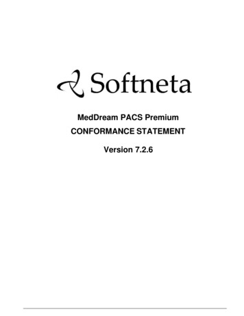
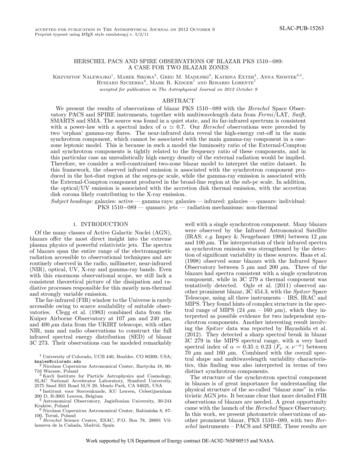
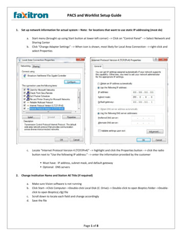
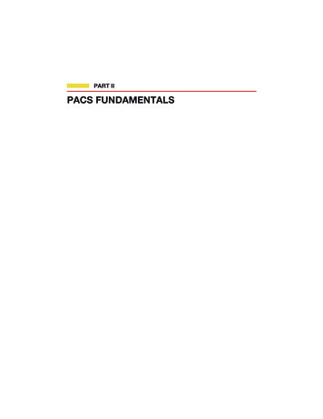
226PICTURE ARCHIVING AND COMMUNICATION SYSTEM COMPONENTS AND WORKFLOWand intelligent bootstrap routines (a software block executed by a computer whenit is restarted) that allow a PACS computer to automatically continue operationsafter a power outage or system failure. Improving reliability is costly; however, itis essential to maintain high reliability of a complex integrated information system.This topic will be considered in depth in Chapter 16.7.2.4SecuritySecurity, particularly the need for patient confidentiality, is an important consideration because of medicolegal issues and the HIPAA (Health Insurance Portabilityand Accountability Act) mandate. There are, in general, three types of data violation: physical intrusion, misuse, and behavioral violations. Physical intrusion relatesto facility security, which can be handled by building management. Misuse andbehavioral violations can be minimized by account control and privilege control.Most sophisticated database management systems have identification and authorization mechanisms that use accounts and passwords. Application programs may supplyadditional layers of protection. Privilege control refers to granting and revoking theuser’s access to specific tables, columns, or views from the database. These securitymeasures provide the PACS infrastructure with a mechanism for controlling access toclinical and research data. With these mechanisms the system designer can enforcepolicy as to which persons have access to clinical studies. In some hospitals, forexample, referring clinicians are granted image study access only after a preliminaryradiology reading has been performed and attached to the image data. Examplesof using fingerprint identification and facial verification are given in Chapters 24and 27.An additional security measure can be implemented in data security and datacommunication security in which image digital signature can be embedded in theimage during its storage and transmission. If implemented, this feature would increasethe system software overhead, but data transmission through open communicationchannels is more secure. Image security is discussed in Chapter 17.7.3A GENERIC PACS WORKFLOWThis chapter emphasizes PACS workflow. For this reason, whenever appropriate, adata workflow scenario will accompany the PACS model at its introduction. Thissection discusses a generic PACS workflow starting from the patient registeringin the HIS, RIS ordering examination, technologist performing the exam, imageviewing, reporting, to image archiving. Compare this PACS workflow with the PACScomponents and workflow is depicted in Figure 7.2, and the radiology workflowshown in Figure 3.1. Clearly, PACS has replaced many manual steps in the film-basedworkflow. Now follow the PACS workflow numerals shown in Figure 7.3:1. Patient registers in HIS, with radiology exam ordered in RIS, and exam accession number automatically assigned.2. RIS outputs HL7 messages of HIS and RIS demographic data to PACS broker/interface engine.3. PACS broker notifies the archive server of the scheduled exam for the patient.
A GENERIC PACS WORKFLOW227A Generic PACS WorkflowPACS )(10)PACS 4)(9)PACS Review WSs(11)Figure 7.3 Generic PACS workflow. Compare the PACS workflow with the PACScomponents and workflow shown in Figure 7.2, and radiology workflow depicted inFigure 3.1.4. Following on prefetching rules, historical PACS exams of the scheduled patientare prefetched from the archive server and sent to the radiologist reading workstation (WS).5. Patient arrives at modality. Modality queries the PACS broker/interface enginefor the DICOM worklist.6. Technologist acquires images and sends the PACS exam of images acquiredby the modality and patient demographic data to quality control (QC) WS ina DICOM format.7. Technologist prepares the PACS exam and sends to the radiologist the diagnostic WS as the prepared status.8. On its arrival at the radiologist reading WS, the PACS exam is immediatelysent automatically to the archive server. Archive server database is updatedwith the PACS exam as the prepared status.9. Archive server automatically distributes the PACS exam to the review WSsin the wards based on patient location as received from the HIS/RIS HL7message.10. Reading radiologist dictates a report with the exam accession number on thedictation system. The radiologist signs off on the PACS exam with any changes.The archive database is updated with changes and marks the PACS exam assigned-off.11. Transcriptionist fetches the dictation and types a report that corresponds to theexam accession number within RIS.
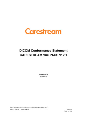
228PICTURE ARCHIVING AND COMMUNICATION SYSTEM COMPONENTS AND WORKFLOW12. RIS outputs HL7 message of results report data along with any previouslyupdated RIS data.13. Radiologist queries the PACS broker for previous reports of PACS exams onthe reading WSs.14. Referring physicians query the broker for reports of PACS exams on the reviewWSs.7.4CURRENT PACS ARCHITECTURESThere are three basic PACS architectures: (1) stand-alone, (2) client-server, and (3)Web-based. From these three basic PACS architectures, there are variations andhybrid design types.7.4.1Stand-alone PACS Model and General Data FlowThe stand-alone model described here is also called thick client model. The threemajor features of the stand-alone model are as follows:1. Images are automatically sent to the designated diagnostic and review WSsfrom the server.2. WSs can also query/retrieve images from the archive server.3. WSs have short-term cache storage.Data workflow of the stand-alone PACS model is shown in Figure 7.4. The numeralsindicate the following:1. RIS notifies the imaging modality and the PACS server of a patient registration.Stand-Alone Model41RIS8PACSServer3: Archive6Q/R5 (Prefetch)12Diagnostic WS7: Local Storage4Review WS7: Local StorageImagingModalityFigure 7.4 Stand-alone PACS model and general data flow. The data flow starts whenRIS notifies imaging modality and the PACS server that a patient has registered (1).Images are sent from the modality to the PACS server (2), PACS server archives theimages (3) and sends to WSs automatically (single-headed red arrows, 4) along withprefetched images (single-headed red arrows, 5); images can also be query/retrieve bythe WSs (double-headed red arrows, 6). All WSs have local storage (7). Diagnosticreports are sent back to the PACS server or directly to RIS (purple arrow, 8).
CURRENT PACS ARCHITECTURES2292. After the examination, the modality sends images to the PACS server.3. PACS server archives the images.4. Multiple copies of the images are distributed to selected diagnostic and reviewWSs. The server performs this image distribution function automatically basedon the default setting.5. Server also prefetches pertinent historical images and sends copies to selectedWSs.6. WSs can also use DICOM query/retrieve function through the server to obtainimages for review. In addition, if automatic prefetching fails, a WS canquery/retrieve historical images from the server.7. Each WS contains a local storage to hold a preset number of PACS exams.8. WS returns the diagnosis to the server then to the RIS.Advantages1. If the PACS server goes down, imaging modalities or acquisition GWs havethe flexibility to send images directly to designated WSs so that radiologistscan continue reading new cases.2. Because multiple copies of the PACS exam are distributed throughout thesystem, there is less risk of losing PACS image data.3. Some historical PACS exams will still be available in WSs because they havelocal storages.4. System is less susceptible to daily variations of network performance becausePACS exams are preloaded onto the WS’s local storage and available forviewing immediately.5. Modification to the DICOM header can be performed if necessary during thequality control before archiving.Disadvantages1. Users must rely on correct image distribution and prefetching of historicalPACS exams based on the preset default table, which is not possible all thetime.2. Because images are sent to designated WSs, each WS may have a different worklist, which makes it inconvenient for radiologists to read/review allexaminations assigned to him/her at any WS in one setting.3. Users sometime need to use query/retrieve function to retrieve pertinent PACSexams from the archive, this task can be a complex function compared to theclient/server model.4. Radiologist may duplicate the reading of the same case from a different WSbecause the same exam may be sent to several WSs.7.4.2Client-Server PACS Model and Data FlowThe client-server model described here is also called thin client model, the threemajor features of the client/server model are as follows:
230PICTURE ARCHIVING AND COMMUNICATION SYSTEM COMPONENTS AND WORKFLOW1. Images are centrally archive in the PACS server.2. From a single worklist at the client WS has a sinlge worklist of all examinationswhere a user selects the patient and images via the PACS server.3. WSs have no local storage, images are flushed after reading.Data flow of the client-server PACS model is shown in Figure 7.5. The numeralsindicate the following steps:1.2.3.4.RIS notifies the imaging modality and the PACS server of a patient registration.After the examination, the modality sends images to the PACS server.PACS server archives the images.Client WSs have access to the complete worklist from where images, andexams can be retrieved from the PACS server and archive. For more efficientimage retrievals, the worklist can be shortened by a preset filter.5. Once the exam is selected, images from the PACS archive are loaded directlyinto the image memory of the client WS for viewing. Prefetched historicalexams are loaded to the WS in the same manner.6. Once the user has completed reading/reviewing the exam, the image data areflushed from memory, leaving no image data in image memory of the clientWS.7. WS returns the diagnosis to the server and then to the RIS.Advantages1. Any exams are available on any PACS WS at any time, making it convenientto retrieve and to read/review.Client-Server Model4, 51R
A Generic PACS Workflow RIS Modality PACS Broker PACS Archive PACS Diagnostic Workstation (1) (2) (5) (7) (4,8) (10) (9) (11) PACS Review WSs (14) (12) (13) (6) (3) Dictation System QC WS Figure 7.3 Generic PACS workflow. Compare the PACS workflow with the PACS components and workflow shown in Figure 7.2, and radiology workflow depictedin .