Transcription
INTERNATIONAL JOURNAL OFCOASTAL & OFFSHORE ENGINEERINGIJCOE Vol.1/No. 3/ Autumn 2017 (29-40)Available online at: http://ijcoe.org/browse.php?a code A-10-157-1&sid 1&slc lang enOn-Bottom Stability Design of Submarine Pipelines – A ProbabilisticApproachHadi Amlashi1Downloaded from ijcoe.org at 13:12 0430 on Wednesday June 16th 20211Schlumberger, Oslo, Norway, hadi.amlashi@gmail.comARTICLE INFOABSTRACTArticle History:Received: 18 Oct. 2017Accepted: 15 Jan. 2018Un-trenched submarine pipelines will experience the wave and current loadsduring their design lifetime which potentially tend to destabilize the pipelineboth horizontally and vertically. These forces are resisted by the interaction ofthe pipe with the surrounding soil. Due to the uncertainties involved in thewaves, currents and soil conditions, there will be a complex interactionbetween the wave/current, pipeline and seabed that needs to be properlyaccounted for. The design of submarine pipelines against excessivedisplacements due to hydrodynamic loads (DNV-RP-F109) is defined as aServiceability Limit State (SLS) with the target safety levels as given in DNVOS-F101 (2013). In this paper, uncertainties associated with the on-bottomstability design of submarine pipelines are investigated. Monte CarloSimulations (MCS) are performed as the basis for the probabilistic assessmentof the lateral stability of the pipeline located on the seabed. Application of themethod is illustrated through case studies varying several design parameters toillustrate the importance of each design parameter for exceeding a giventhreshold of the SLS criterion. Uncertainties in the significant wave height andspectral peak period are found to be important parameters in describing theUtilization Ratio (UR) distribution. Type of the soil has also an impact on thedistribution of UR, i.e. how the passive soil resistance in the pipe-soilinteraction model is accounted for. Therefore, the definition of characteristicvalues of both loads and resistance variables are important for the UR.Keywords:Submarine pipelinesOn-bottom Lateral StabilityServiceability Limit State (SLS)DNV-OS-F101DNV-RP-F109Monte Carlo Simulation (MCS)WaveCurrentSoil Passive Resistancetechnically sound basis for the on-bottom lateralstability design of submarine pipelines [2,3]. Otherresearches performed are: (1) the AGA project [4],and (2) a research project at the Danish HydraulicInstitute (DHI) [5]. Based on these researches, severalpipe-soil interaction models were introduced.In a typical pipe–soil interaction model, the total soillateral resistance to pipeline movement, 𝐹𝐻 , isassumed to be the sum of the sliding (friction)resistance component (𝐹𝑓 ) and the soil passiveresistance component (𝐹𝑅 ), i.e.1. IntroductionOffshore pipelines have long since been an efficientmeans of transport for oil and gas. Submarinepipelines as installed upon seabed are subject to wavesand currents. Moreover, uncertain or unknown soilconditions are a common cause of construction delaysand cost escalations for submarine pipeline projects.There exists a complex interaction betweenwaves/currents, the pipeline, and the seabed that needsto be properly accounted for.To mitigate the lateral instability of a pipeline leftexposed on the seabed, either the pipeline should bestabilized using an appropriate concrete weightcoating or a thicker wall thickness, or beanchored/trenched locally. Both methodologies areexpensive and complicated from design andconstruction/installation point of view.Several studies have been performed to investigate themajor physical phenomena involved in predicting thelateral stability of un-trenched pipelines on the seafloor. Among, was the Pipeline Stability Design(PIPESTAB) JIP [1] which included both analyticaland experimental investigations to arrive at a𝐹𝐻 𝐹𝑓 𝐹𝑅 𝜇(𝑊𝑠 𝐹𝐿 ) 𝐹𝑅(1)where 𝜇 friction (resistance) coefficient; 𝑊𝑠 pipeline submerged weight per meter, 𝐹𝐿 lift forceupon pipeline per meter and 𝐹𝑅 soil passiveresistance per meter which depends on the soilbuoyant weight and the contact area between thepipeline and the soil. The lateral soil resistance (𝐹𝐻 )should balance the designed wave/current loads uponthe pipeline, which can be calculated with the wakemodel proposed by [6] considering the oscillatoryflow over the pipeline.29
Hadi Amlashi / On-Bottom Stability Design of Submarine Pipelines – A Probabilistic ApproachDownloaded from ijcoe.org at 13:12 0430 on Wednesday June 16th 2021The outcome of the above-mentioned researches hasbeen the basis for further development of DNV-RPF109 (2011) [7]. For the lateral on-bottom stability,three different design methods are described in DNVRP-F109 (2011):uncertainties are important for correctly accounting ofthe passive soil resistance.From the design point of view, the stability ofsubmarine pipelines against excessive displacementdue to hydrodynamic loads is normally ensured by theuse of a Load and Resistance Factors Design Format(LRFD), as given e.g. in DNV-RP-F109 (2011). Theexcessive lateral displacement due to the action ofhydrodynamic loads is defined as a ServiceabilityLimit State (SLS) with the target safety levels given inDNV-OS-F101 (2013) [9]. If this displacement leadsto significant strains and stresses in the pipe itself,these load effects should be dealt with in accordancewith relevant codes, e.g. DNV-OS-F101 (2013).Generally, SLS criterion is a condition which, ifexceeded, renders the pipeline unsuitable for normaloperations. In DNV-OS-F101 (2013), exceedance of aSLS category are evaluated as an Accidental LimitState (ALS).To document how the variability in hydrodynamicloads and the soil behaviour and their interactions areaccounted for in the traditional design practices, aprobabilistic approach is therefore introduced.In this paper Monte Carlo Simulations (MCS) areperformed as the basis for the probabilistic assessmentof the lateral stability of the pipeline located on theseabed. Application of the method is illustratedthrough case studies to illustrate the importance ofeach design parameter for exceeding a given thresholdof the SLS criterion.1) Dynamic lateral stability analysisThe dynamic lateral stability analysis is based on atime domain simulation of the pipe response,including hydrodynamic loads from an irregular seastate, soil resistance forces, boundary conditions andthe dynamic response of pipeline. Usually, thedynamic analysis forms the basis for the validation ofother simplified methods such as the generalizedanalysis method. Therefore, it is normally used for thedetailed analysis of critical areas along a pipeline,such as pipeline crossings, riser connections etc.,when the uncertainties in the design parameters callsfor a detailed assessment.2) Absolute lateral static stability methodAn absolute static requirement for the lateral onbottom stability of pipelines is based on the staticequilibrium of forces that ensures the resistance of thepipe against motion is sufficient to withstandmaximum hydrodynamic loads during a sea state, i.e.the pipe will experience no lateral displacement underthe design extreme single wave-induced oscillatorycycle in the sea state considered. One should,however, note that this approach does not account forthe increased passive resistance that is built up due tothe pipeline penetration caused by the wave-inducedflow. The absolute stability method may be relevantfor e.g. pipe spools, pipes on narrow supports, casesdominated by current and/or on stiff clay.2. On-bottom Stability - Design MethodologyThe on-bottom stability design of submarine pipelinesis normally performed using DNV-RP-F109 (2011)together with DNV-OS-F101 (2013). Design methodsand acceptance criteria for vertical and lateral stabilityof pipelines on the seabed are briefly explained below.Vertical StabilityFor the vertical stability, a simple design equation,based on sinking in the sea water, is presented. Thecriterion is defined based on a single safety factor onthe total weight per unit length as bellow:3) Generalized lateral stability methodThe generalized lateral stability method is based on anallowable displacement in a design spectrum ofoscillatory wave-induced velocities perpendicular tothe pipeline at the pipeline level. This can beperformed for No-Break Out (NBO), i.e. displacement 0.5 diameter or a multiplier of pipeline diameter(limited by 10).The soil behaviour in each application is not always inaccordance with its soil classification. This isparticularly true when the particle size distributionfalls near the classification boundary of coarse/finesoils and soil classification alone may not fullycapture the soil behaviour for aspects of design andoperation [8]. Therefore, proper knowledge of howthe soil classification is carried out and its limitations,is required in order to use the geotechnical survey datacorrectly and efficiently. This is particularly importantwhen performing the on-bottom lateral stabilityanalysis of a pipeline subject to waves and currents.This is because the interaction between waves,currents and soils and their corresponding𝑊𝑑𝑟𝑦 γ𝑤 𝑏(2)ors𝑔 γ𝑤(3)where s𝑔 is the pipe specific density defined as 1 𝑊𝑠 𝑏 and γ𝑤 is the weight safety factor. Normally, asafety factor of γ𝑤 1.1 is used. The 𝑊𝑠 is thesubmerged weight of the pipeline defined as 𝑊𝑠 𝑊𝑑𝑟𝑦 𝑏, the buoyancy 𝑏 𝜌𝑤 𝑔𝜋 𝐷 2 4 and 𝐷 is theouter diameter including all coatings. The dry weightof the pipeline (𝑊𝑑𝑟𝑦 ) reads:𝑊𝑑𝑟𝑦 𝑊𝑠𝑡𝑒𝑒𝑙 𝑊𝑐𝑜𝑎𝑡𝑖𝑛𝑔 𝑊𝑐𝑜𝑛𝑡𝑒𝑛𝑡30(4)
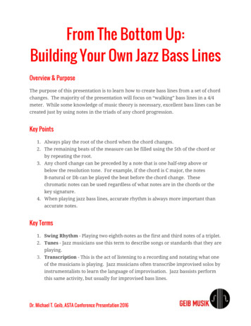
Hadi Amlashi / IJCOE 2017, 1(3); p. 29-40This approach is very time consuming and requiresthe design data to be available, i.e. in later designphases (detail design) where optimization of thepipeline weight may be possible due to the availabilityof site-specific environmental data.Lateral StabilityFor the lateral stability, both Coulomb frictionresistance and the passive resistance from soil areaccounted for. A general design criterion is presentedas below:(5)A typical Displacement curve established based on dynamic simulationswhere 𝑌 is the non-dimensional lateral pipedisplacement (𝑌 𝑦/𝐷), the vector X contains maindesign parameters influencing the accumulateddisplacement (y) and 𝑌𝑎𝑙𝑙𝑜𝑤𝑎𝑏𝑙𝑒 is the allowed nondimensional lateral displacement (scaled to the pipediameter). The 𝑌𝑎𝑙𝑙𝑜𝑤𝑎𝑏𝑙𝑒 shall be defined based ondesign conditions, but generally the total accumulateddisplacement is limited to 10-pipe diameter.For the lateral on-bottom stability, three differentdesign methods are presented:1) A dynamic lateral stability analysis2) An absolute lateral static stability method.3) A generalized lateral stability method basedon database results from dynamic analysesThese methods are briefly addressed and theuncertainties involved are discussed subsequently.100Log(Dimentionless displacement Y)Downloaded from ijcoe.org at 13:12 0430 on Wednesday June 16th 2021𝑌(𝑿) able)101Min. allowedsubmerged weight0,1110100Log (Dimensionless weight parameter)Figure 1 A typical Normalized Displacement versusNormalized Weight (typically shown for results from dynamicanalyses)Dynamic lateral stability analysisThe most complete approach for on-bottom lateralstability of a pipeline is to perform a dynamicsimulation.The dynamic response of a pipeline depends on waveto current ratio, wave period and soil type andpenetration (passive resistance). Due to highnonlinearities involved in the response of the pipeline,a complete sea state should be used. In lack of properfull sea state data, a 3-hours sea state data shall beused.Time-domain simulations are performed to calculatethe accumulated lateral displacement of a pipelinesubjected to hydrodynamic loads from waves, currentsand soil resistance forces.A typical result from the dynamic on-bottom stabilityanalyses is shown in Figure 1. An envelope curve istypically established based on many analysis cases tocalculate the maximum allowable displacement. Timeincrements should be small enough to capture theactual nonlinear behaviour of the pipe-soil interaction.Furthermore, the axial force (due to internal pressureand temperature) and end effects should properly beaccounted for. Also, the wave directionality togetherwith the maximum wave height and thesequence/number of waves must be accounted for.Hence, many analyses should be performed toestablish a representative envelope curve. Normally, aparametric study is performed to cover a displacementranges of zero to several diameters of the pipeline.It should be noted that the 𝑌𝑎𝑙𝑙𝑜𝑤𝑎𝑏𝑙𝑒 may further belimited due to the excessive bending of the pipelineand other constraints.However, in earlier phases of design, e.g. feasibilityand/or conceptual design stages, simpler yet reliabledesign approaches are required to ensure the onbottom stability of the pipeline accounting for theuncertainties in environmental loads and the soilbehaviour.Absolute lateral stability methodThe absolute lateral stability criteria, in DNV-RPF109 (2011), are defined in terms of UR (UtilisationRatio) as described below:𝜇𝐹 𝐹 𝑈𝑅𝐴𝑆,1 γ𝑆𝐶 𝜇𝑊𝑍 𝐹𝑌 1𝑠𝐹 𝑅𝑈𝑅𝐴𝑆,2 γ𝑆𝐶 𝑊𝑍 1𝑠(6)(7)where, γ𝑆𝐶 Safety factor for Safety Class and 𝜇 Friction coefficient. The design Peak load coefficients(𝐶𝑧 and 𝐶𝑦 ), ref. to Eqs. (13) and (14) and arecalculated from design tables in DNV-RP-F109(2011) by interpolations of design parametersKeulegan-Carpenter number (𝐾 𝑈 𝑇 𝐷) andsteady to oscillatory velocity ratio (𝑀 𝑉 𝑈 ) fora single design oscillation.The above criteria can be stated in terms of minimumrequired submerged weight (𝑊𝑠,𝑟𝑒𝑞. ). It means, thecriterion can read:𝑊𝑠𝑊𝑠,𝑟𝑒𝑞. 1(8)The relation between the Utilisation Ratio (𝑈𝑅) andthe minimum required submerged weight (𝑊𝑠,𝑟𝑒𝑞. ) for31
Hadi Amlashi / On-Bottom Stability Design of Submarine Pipelines – A Probabilistic Approachboth lateral and vertical stabilities, in Eqs. (6) and (7) ,can then be written as follow:𝑈𝑅𝐴𝑆,1 𝑈𝑅𝐴𝑆,2 𝜇𝑊𝑠,𝑙𝑎𝑡,𝑟𝑒𝑞. 𝐹𝑅𝜇𝑊𝑠 � 1 1Downloaded from ijcoe.org at
displacements due to hydrodynamic loads (DNV-RP-F109) is defined as a Serviceability Limit State (SLS) with the target safety levels as given in DNV-OS-F101 (2013). In this paper, uncertainties associated with the on-bottom stability design of submarine pipelines are investigated. Monte Carlo Simulations (MCS) are performed as the basis for the probabilistic assessment of the lateral stability .