Transcription
2005Elements of DesignCHAPTER 3ELEMENTS OF DESIGN3.0 INTRODUCTIONThe design of highways and streets within particular functional classes is treated separately inlater chapters. However, common to all classes of highways and streets are several principalelements of design, which include sight distance, superelevation, traveled way widening, grades,and horizontal and vertical alignments. These alignment elements are discussed in this chapter,and, as appropriate, in the later chapters pertaining to specific highway functional classes.The alignment of a highway or street produces a great impact on the environment, community,and highway user. The alignment is comprised of a variety of elements joined together to createa facility that serves the traffic in a safe and efficient manner, consistent with the facility’sintended function. Each alignment element should complement the others to produce aconsistent, safe, efficient, and environmentally responsible design.3.1 SIGHT DISTANCE3.1.1 General ConsiderationsA critical element in assuring safe and efficient operation of a vehicle on a highway is the abilityto see ahead. Sight distance is the distance along a roadway throughout which an object ofspecified height is continuously visible to the driver. This distance is dependent on the height ofthe driver's eye above the road surface; the specified object height above the road surface; andthe height and lateral position of sight obstructions such as cut slopes, guardrail, and retainingwalls within the driver's line of sight. Sight distance of sufficient length must be provided toallow drivers to avoid striking unexpected objects in the traveled way. Certain two-lanehighways should also provide sufficient sight distance to allow drivers to occupy the opposinglane for passing without hazard.Sight distance falls into three categories: Stopping (applicable on all highways)Passing (applicable only on two-lane highways)Decision (applicable at complex locations)3.1.2 Stopping Sight DistanceStopping sight distance is the sum of two distances: The distance a vehicle travels from the instant the driver sights an object necessitating a stopto the instant the brakes are applied (brake reaction distance), andThe distance required to stop the vehicle from the instant brake application begins (brakingdistance).3-1
Elements of Design2005Stopping sight distance is measured from the driver’s eyes, which are assumed to be 3.5 feetabove the pavement, to an object 2 feet high on the road. Distances greater than the minimumstopping sight distance provide an additional measure of safety and should be considered wherepractical.Stopping sight distances may be determined directly by calculating braking distance and brakereaction distance, and adding these values together, as described in the PGDHS (1). Table 3-1 ofthis Guide shows sight distances for level roadways and roadways with grade for various designspeeds. See also section 3.1.2.1 for adjustments for grades .Passing SightDistance(2-Lane Road)Stopping Sight Distance (Design Values)DesignSpeedNo gradeadjustment% Down Grade% Up GradeCrestSag(mph)Dist. 49560Crest VerticalCurveDist. le 3-1 Sight DistanceK LAWhere:L Length of curve, ftA Algebraic difference in intersecting grades, in percent3-2
2005Elements of DesignK value is a coefficient by which the algebraic difference in grade may be multiplied todetermine the length in feet of the vertical curve that will provide minimum sight distance.Values of K 167 or greater should be checked for drainage.3.1.2.1 Effect of Grade on Stopping Sight DistanceThe safe stopping distances on upgrades are shorter; those on downgrades are longer. Designspeed is used in calculating downgrade corrections; average running speed in calculating upgradecorrections. The different criteria for descending and ascending grades are based on the effectgrades have on the speed of individual vehicles, particularly trucks; the effect these vehicles haveon the overall speed of the traffic stream; and the premise that many drivers, particularly those inautomobiles, do not compensate completely for the changes in speed caused by grades.On nearly all roads and streets, the grade is traversed by traffic in both directions, but the sightdistance at any point on the highway generally is different in each direction, particularly onstraight roads in rolling terrain. As a general rule, the sight distance available on downgrades islarger than on upgrades, more or less automatically providing the necessary corrections forgrade. Exceptions are one-way roads or streets, as on divided highways with independent designprofiles for the two roadways, for which the separate grade corrections are in order and therefinement in design is in keeping with the overall standards used.For those areas where there is a high volume of trucks, review “Variations for Trucks” inChapter 3 of the PGDHS (1). See Table 3-1 for grade adjustments.3.1.3 Decision Sight DistanceExhibit 3-3 (1) provides values for appropriate decision sight distances at critical locations andfor criteria in evaluating the suitability of the sight lengths at these locations.Stopping sight distance may not be adequate when drivers are required to make complex orinstantaneous decisions, when information is difficult to perceive, or when unexpected orunusual maneuvers are required. In these instances, stopping sight distances may not providesufficient visibility distance for drivers to corroborate advance warnings and to perform thenecessary maneuvers. Decision sight distance provides the greater length that drivers need.Decision sight distance is the distance required for a driver to: Detect an unexpected or otherwise difficult to perceive information source or hazard in aroadway environment that may be visually cluttered. Recognize the hazard or its threat potential. Select an appropriate speed and path. Initiate and complete the required safety maneuver safely and efficiently.3-3
Elements of Design2005Drivers need decision sight distances whenever there is a likelihood for error in eitherinformation reception, decision making, or control actions. The following are examples ofcritical locations where these kinds of errors are likely to occur and where it is desirable toprovide decision sight distance: Interchange and intersection locations where unusual or unexpected maneuvers are required. Changes in cross section such as toll plazas and lane drops. Areas of concentrated demand where there is apt to be "visual noise" whenever sources ofinformation compete, as those from roadway elements, traffic, traffic control devices, andadvertising signs.3.1.4 Sight Distance on Horizontal CurvesSight distance on horizontal curves may be obtained with the aid of Figures 3-1 and 3-2 andTable 3-1 of this Guide and Exhibit 3-8 (1). For passenger vehicles, it is assumed that thedriver’s eyes are 3.5 feet above the center of the inside lane (inside with respect to the curve) andthe object is 2 feet high. The line of sight is assumed to intercept the obstruction at the midpointof the sight line and 2 feet above the center of the inside lane. The middle horizontal sightlineoffset (HSO) is obtained from Figure 3-1.Horizontal sight distance may be measured with a straightedge, as indicated in Exhibit 3-8 (1).3-4
2005Elements of DesignAs a matter of general case, consider the following:Figure 3-1 General Case – Stopping Sight Distance on Horizontal CurvesWhere:Ri radius from centerline (C.L.) of inside lane (feet).HSO horizontal sightline offset (feet) (lateral distance from centerline of inside lane toROW line or obstruction.S available stopping sight distance (feet)3-5
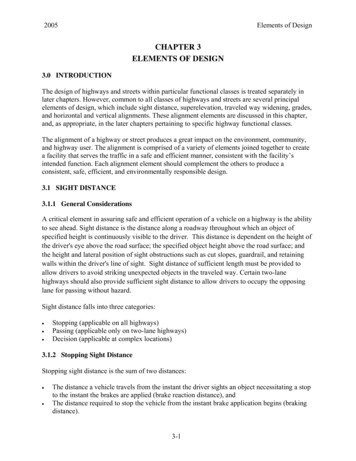
Elements of Design2005To obtain Stopping Sight Distance, consider the following:Figure 3-2 [Exhibit 3-53 (1)] Design Controls forStopping Sight Distance on Horizontal CurvesNote: this figure does not consider the effects of grade.3-6
2005Elements of DesignFigure 3-3 Example of Horizontal Stopping Sight Distance on a Two-Lane Roadway12 1426.5 ft212HSO 33.5 27.5 ft21426.51426.5 27.5cos 1 S 561 ft28.651426.5Ri 1432.5 3-7
Elements of Design2005Figure 3-4 Example of Horizontal Stopping Sight Distance on a Ramp12 1438.5 ft212HSO 33.5 39.5 ft21438.5 39.51438.5 S 676 ftcos 11438.528.65Ri 1432.5 3-8
2005Elements of DesignFigure 3-5 Example of Horizontal Stopping Sight Distance on Divided Highways1212 12 1408.5 ft221212HSO 67.5 12 43.5 ft221408.51408.5 43.5cos 1 S 702 ft28.651408.5Ri 1432.5 Note: If a divided highway has median barrier, the horizontal stopping sight distance for theinside lane of the opposite direction should also be checked and shoulder widening considered.See Design Aid 100.3-9
Elements of Design20053.1.5 Sight Distance on Vertical Curves3.1.5.1 Crest Vertical CurvesStopping sight distance is measured when the height of eye and the height of object are 3.5 feetand 2 feet respectively.When S is less than L,S 2158LA(i)When S is greater than L,S L 1079 2A(ii)L length of vertical curve, in feetA algebraic difference in grades, in percentS Sight distance, in feetFigure 3-6 Example of Crest Vertical Curve3-10
2005Elements of DesignGiven:Try (ii):L 400 feet, find S, K and design speedL 1079 400 1079 2A22.49S 633 ft L(400) OKL 400K 160.6A 2.49From Table 3-1 for a K(CREST) value of160.6, V 60 mph.S V.A 1.0 - (-1.49) 2.49Since it is unknown whether S L or S L,try (i):(2158)(400)2158 L A2.49S 589 ftS (589) L(400) No GoodS 3.1.5.2 Sag Vertical CurvesHeadlight sight distance is the basis for determining the length of sight distance. Prior tocalculating the following formula, review Exhibit 3-74 (1) to ascertain if S is less than or greaterthan L.When S is less than L,3.5 L 12.25L2 1600 ALS 2A(iii)When S is greater than L,S AL 4002 A 3.5(iv)Where:L length of sag vertical curve, in feetS light beam distance, in feetA algebraic difference in grades, in percent3-11
Elements of Design2005Figure 3-7 Example of Sag Vertical CurveGiven:L 300 feet, check if curve is adequate for a design speed of 40 mph, and find S.A 2.5 - (-2.0) 4.5L 300K 66.7A 4. 5From "Sag K" column of Table 3-1, with K(Sag) value of 66.7, V 40.9 mph. Curve is adequate for a design speed of 40 mph.Since it is unknown whether S L or S L, try each equation or consult Exhibit 3-74(1).try (iii):3.5 L 12.25L2 1600 ALS 2A(3.5)(300) (12.25)(300) 2 (1600)(4.5)(300) (2)(4.5) 317, which is 300 No good!Try (iv):S AL 400 (4.5)(300) 400 318 ft, which is 300 .OK!(2)(4.5) 3.52 A 3.53.1.6 Passing Sight DistancePassing sight distance is the minimum sight distance required for the driver of one vehicle topass another vehicle safely. Passing sight distance is considered only on two-lane roads. Passingsight distance is measured between an eye height of 3.5 feet and an object height of 3.5 feet.Table 3-1 presents minimum passing sight distances for various design speeds.3-12
2005Elements of DesignGenerally, it is impractical to design crest vertical curves to provide for passing sight distancebecause of the high cost where crest cuts are involved and the difficulty of fitting the requiredlong vertical curves to the terrain, particularly for high speed roads.Passing sight distance calculations are for design purposes only to assist in providing as manypassing opportunities as possible. Actual passing and no-passing zone locations for striping needto be field measured and placed in accordance with the Manual on Uniform Traffic ControlDevices (MUTCD) (2).3.1.6.1 Passing Sight Distance on Crest Vertical CurvesDesign values of crest vertical curves for passing sight distance differ from those for stoppingsight distance because of the different height criterion; i.e., 3.5 feet for the height of object forpassing sight distance compared to 2 feet for stopping sight distance. The following formulasapply:When S is less than L,2800LS AWhen S is greater than L,L 1400S A2For minimum passing sight distances, the required lengths of crest vertical curves aresubstantially longer than those for stopping sight distances, as evidenced by the values in Table3-1. These lengths are significantly greater than the lengths necessary for stopping sightdistances.3.1.6.2 Passing and Stopping Sight Distances at UndercrossingsIf economically feasible, passing sight distance should be maintained as the highway passesunder a structure. On occasion, topographic conditions may result in a pronounced sag curve andthe underside of the structure may limit the sight distance. Such conditions may best be checkedgraphically on the profile using the vertical clear dimension of the structure, the height of the eyefor a truck driver as 8 feet and the height of object as 2 feet for the taillights of a vehicle.Minimum stopping sight distance must be maintained. See Exhibit 3-76 (1).3.2 HORIZONTAL ALIGNMENT3.2.1 General ControlsHorizontal alignment should provide for safe and continuous operation of vehicles at a uniformdesign speed for substantial lengths of highway.The major considerations in horizontal alignment are:3-13
Elements of Design 2005TopographyType of facilityDesign speedProfile gradeSubsurface conditionsExisting highway and cultural developmentLikely future developmentsLocation of the highway terminalsRight of waySafetyConstruction costsEnvironmental issuesGeological featuresDrainageAll the above considerations should be balanced to produce an alignment that is appropriate forthe location and functional classification of the highway. (Functional classification is explainedin Chapter 1.)To a large extent, topography controls both curve radius and design speed. In mountainous areasor areas subject to icing, consideration should be given to locating the road so that a southernexposure will be obtained wherever possible.Geological features that may affect design, such as potential slide areas and subsurface water,should be investigated by the Materials and Geotechnical Branch.Sight distance, compatible with the selected design speed, is required for proper design. Stoppingsight distances are discussed in 3.1 Sight Distance.Horizontal alignment must afford at least the minimum stopping sight distance for the designspeed at all points on the highway, as given in Table 3-1.Every effort should be made to exceed the minimum curve radii. Minimum curve radii should beused only when the cost of realizing a higher standard is not consistent with the benefits. Thefinal considerations for the safety of any curve should be the combination of the factors ofradius, sight distance, and superelevation (see section 3.2.3).To avoid the appearance of inconsistent distribution, the horizontal alignment should becoordinated carefully with the profile design. General controls for this combination are discussedin section 3.4.3.2.2 Types and Properties of Horizontal Alignments3.2.2.1 Simple Curves3-14
2005Elements of DesignA simple curve is a circular arc joining two tangents.Figure 3-8 Simple CurveWhere:R radius of curve, ftL length of curve in stations deflection angle between the tangents, decimal degreesT length of tangent, ftE external distance, ft3.2.2.2 Spiral CurvesSpiral curves provide a gradual change in curvature from a straight to a circular path. Spiraltransitions are not required but may be used on all roadways including ramps whererecommended by the CDOT Standard Plans - M & S Standards (3) on superelevation, whichalso includes minimum transition lengths to be used with any given curvature and speed.3-15
Elements of Design2005Figure 3-9 Spiral CurveP is any point on the spiral curve.Equations for the spiral curve are as follows: Ts (Rc ρ )TAN k 2 3-16
2005Elements of Design 1 1 ρE s (Rc ρ ) COS 2 R ρ c Rc cos2Ls 200 θ sDc2 Lθ Ls θs LD Ls Dc (y ls30.5818θ s 0.1266 10 4 θ s100x ls(100 0.3046 10 2 θ 32 )100)Where L is in feet and θ is measured in decimal degrees.ρ 0.001454θsLsk Ls(0.5 - 5.0770 10-6θs2)where θ is measured in decimal degrees.Where:TS point of change from tangent to spiralSC point of change from spiral to circleCS point of change from circle to spiralST point of change from spiral to tangentL spiral arc from the TS to any point on spiralLs total length of spiral from TS to SCθ central angle of spiral arc Lθs central angle of spiral arc Ls, called "spiral angle"Φ spiral deflection angle at the TS from initial tangent to any point on spiralD degree of curve of the spiral at any point3-17
Elements of Design2005R radiusDc degree of curve of the shifted circle to which the spiral becomes tangent at the SCRc radius of curve of the shifted circle to which the spiral becomes tangent at the SC total central angle of the circular curve c central angle of circular arc of length Lc extending from SC to CSy tangent offset of any point on spiral with reference to TS and initial tangentys tangent offset at the SCx tangent offset of any point on spiral with reference to TS and initial tangentxs tangent distance for the SCρ offset from the initial tangent to the PC of the shifted circlek abscissa of the shifted PC referred to the TSTs total tangent distance distance from PI to TS, or from PI to STEs total external distanceFor further information on spiral curves, see Route Location and Design by T .H. Hickerson (4).3.2.2.3 Reverse CurvesTwo consecutive circular curves constitute a reverse curve if they join at a point of tangencywhere their centers are on opposite sides of the common tangent. True reversing curves shouldbe avoided, although they may at times be used in designing detours. In cases of reversingcurves, a sufficient tangent should be maintained to avoid overlapping of the requiredsuperelevation runoff and tangent runout (see section 3.2.3).3-18
2005Elements of DesignFigure 3-10 Reverse Curves3-19
Elements of Design2005PRC Point of Reversing Curvature.In Case 1, the two parallel tangents are to be connected by a reversed curve (such as in a detour).R1, R2, and p are given.From triangle 1,From which,L1 sin R1L1 R1 sin andR1 m2 cos R1m2 R1 (1 cos )p m2 m1p R1 (1 cos ) R2 (1 cos )p (R1 R2 )(1 cos )p 1 cos R1 R2(i)andD L1 L2D R1 sin R2 sin D ( R1 R2 ) sin From triangle 2,L2 sin R2andR2 m1 cos R2(ii)(iii)m2 R2 (1 cos )From equations (i) (ii) and (iii) and the ordinary functions of a simple curve, all ordinary cases ofreversed curves between parallel tangents can be solved.In Case 2, the two tangents, intersecting with the angle θ, are to be connected by the reversedcurve in which T1, R1, and R2 are known, and the tangent distance T2 and the central angles ofthe two branches ( 1 & 2) are required.In triangle 1, the base T1 and the angles are known, from which the sides d and m can becomputed.In triangle 2, the hypotenuse is Rl -m, and the angles are known from which the base p and thealtitude n are determined.In triangle 3, the base is R2 p, and the hypotenuse is Rl R2, from which the angles 2 and band the distance q can be found.Then 1 θ 2and T2 d n q3-20
2005Elements of Design3.2.2.4 Compound CurvesTwo consecutive circular curves constitute a compound curve if they join at a point of tangencywhere both curves are on the same side of the common tangent.A compound curve on open highways should be avoided, particularly where a simple curve canbe obtained at small extra cost. Where topography makes their use necessary, the ratio of theflatter radius to the sharper radius should not exceed 1.5:1. For compound curves at intersectionsor on ramps, the ratio of the flatter radius to the sharper radius should not exceed 2:1. When thisis not feasible, an intermediate simple curve or spiral should be used to provide the necessarytransitions. Refer to the PGDHS (1), Chapter 3 for more discussion on compound curves atintersections3-21
Elements of Design2005Figure 3-11 Compound Curve3.2.2.5 Alignment on BridgesEnding a curve on a bridge is undesirable and adds to the complication of design andconstruction. Likewise, curves beginning or ending near a bridge should be placed so that no partof the spiral or superelevation transitions extends onto the bridge. Compound curves on a bridgeare equally undesirable. If curvature is unavoidable, every effort should be made to keep thebridge within the limits of the simple curve.3-22
2005Elements of Design3.2.2.6 Curvature ZoningIn addition to the specific design elements for horizontal alignment discussed under previousheadings, a number of general controls are recognized in practice. These controls are not subjectto theoretical derivation, but they are important for efficient and smooth-flowing highways.Excessive curvature or poor combinations of curvature limit capacity, cause economic lossesbecause of increased travel time and operating costs, and detract from a pleasing appearance. Toavoid such poor design practices, the general controls that follow should be used where practical.Consistent alignment should always be sought. Sharp curves should not be introduced at the endsof long tangents. Sudden changes from areas of flat curvature to areas of sharp curvature shouldbe avoided. Where sharp curvature is introduced, it should be approached, where practical, by aseries of successively sharper curves. Broken-Back CurveA broken-back curve consists of two curves in the same direction joined by a short tangent(under 1,500 feet). Broken-back curves are undesirable. If used, a simple curve, a compoundcurve or spiral transitions should be used to provide some degree of continuoussuperelevation. Lengths need to be adequate to transition superelevation correctly.The “broken-back” arrangement of curves should be avoided except where very unusualtopographical or right of way conditions make other alternatives impractical. Small Deflection AnglesFor small deflection angles, curves should be sufficiently long to avoid the appearance of akink. Curves should be at least 500 feet long for a central angle of 5 degrees, and theminimum length should be increased 100 feet for each 1 degree decrease in the central angle.Horizontal curves should not be used when the central angle is 59 minutes or less. Passing TangentsPassing tangents are used to provide passing opportunities on two-lane roads. One-half mileis considered an adequate length. Passing tangents should be provided as frequently aspossible in keeping with the terrain.An effort to introduce a passing tangent or to increase the length of a passing tangent isalways worthy of reasonable expenditure. Nothing is gained if sweeping curves of large radiiare used at the ends of a tangent if they reduce its length to less than that required for safepassing. It is better to use somewhat shorter radii and increase the intervening tangent to amore satisfactory length. At the other extreme, sharp curves at the ends of a passing tangentshould be avoided as indicated above.3-23
Elements of Design20053.2.3 Superelevation3.2.3.1 GeneralOne of the most important factors to consider in highway safety is the centrifugal force generatedwhen a vehicle traverses a curve. Centrifugal force increases as the velocity of the vehicle and/orthe degree of curvature increases.To overcome the effects of centrifugal force, curves must be superelevated. It is impossible tobalance centrifugal force by superelevation alone, because for any given curve radius a certainsuperelevation rate is exactly correct for only one driving speed. At all other speeds there will bea side thrust either outward or inward, relative to the curve center, which must be offset by sidefriction. See the PGDHS (1) for further discussions on side friction.See section 3.5 for superelevation of detours.3.2.3.2 Standards for SuperelevationThe CDOT Standard Plans – M & S Standards (3) on Superelevation give the required rate ofsuperelevation for the various radius lengths at different design speeds for the maximumsuperelevation rate. See Standard Plans M-203-10, 11, 12, and 13. The values in the standardplans match those in Exhibits 3-25, 3-26, and 3-27 (1).See section 3.5.6 for superelevation of detours.A lower maximum rate of superelevation is generally used in urban areas than in rural areas.The maximum superelevation rate may be less than shown on CDOT Standard Plans – M & SStandards (3) when the designer determines that the lower rate is required because of trafficcongestion or extensive marginal development that acts to restrict top speeds.For divided highways where median width is less than 60 feet, future inside widening of bridgesor providing additional lanes requires the designer to properly plan the superelevation. Things toconsider are: superelevation pivot point vertical clearance superelevation transitions3.2.3.3 Superelevation TransitionSuperelevation runoff is the term denoting the length of highway needed to accomplish thechange in cross slope from a section with the adverse crown removed (one side superelevates atnormal crown slope, the other side at zero slope) to the fully superelevated section, or vice versa.When a spiral is used, its length is used to accommodate the superelevation runoff.3-24
2005Elements of DesignTangent runout is the term denoting the length of highway needed to accomplish the change incross slope from a normal crown section to a section with the adverse crown removed (one sidesuperelevates at normal crown slope, the other side at zero slope), or vice versa.The length of the tangent runout is determined by the amount of adverse crown to be removedand the rate at which it is removed. This rate of removal should be the same as the rate used toeffect the superelevation runoff.The location, with respect to the curve, and the various lengths of the superelevation transitionsare shown on the CDOT Standard Plans - M & S Standards on Superelevation (3).3.2.3.4 Design for All Rural Highways, Urban Freeways and High-Speed Urban StreetsOn all rural highways, urban freeways, and urban streets where speed is relatively high andrelatively uniform, horizontal curves are generally superelevated and successive curves aregenerally balanced to provide a smooth-riding transition from one curve to the next.Exhibit 3-15 (1) gives minimum curve radius in feet for specific design speeds and the rates ofsuperelevation. The table is based on design speed and superelevation alone and does notconsider the sight distance factor.3.2.3.5 Design for Low-Speed Urban StreetsAlthough superelevation is advantageous for traffic operations, various factors often combine tomake its use impractical in many built-up areas. Such factors include wide pavement areas; needto meet the grade of adjacent property; surface drainage considerations; and frequency of crossstreets, alleys and driveways. Therefore, horizontal curves on low-speed streets in urban areasare frequently designed without superelevation, counteracting the centrifugal force solely withside friction. On these curves, traffic entering a curve to the left has an adverse or negativesuperelevation due to the normal crown, but with flat curves and lower speeds the resultantfriction required to counteract both the centrifugal force and the negative superelevation is small.On successively sharper curves for the same design speed, the maximum degree of curvature orsharpest curve without superelevation is reached when the side friction factor developed tocounteract centrifugal force and adverse crown reaches the maximum allowable value based onsafety and comfort considerations. For travel on sharper curves, superelevation is needed.The maximum superelevation rate of zero in Table 3-2 establishes the minimum radius for eachspeed below which superelevation is not provided on local streets in residential and commercialareas but should be considered in industrial areas or other streets where operating speeds will behigher. A maximum superelevation rate of 4 percent or 6 percent is commonly used. Themaximum curvature for a given design speed is defined for low-speed urban streets when boththe maximum superelevation rate and the maximum allowable side friction factors are utilized.3-25
Elements of .84.04.24.44.64.85.05.25.45.65.86.02005R (feet) for Design Speed 349408214623434640811452333433981144231340Notes1. Computed using Superelevation Distribution Method 2.2. Superelevation may be optional on low-speed urban 68662655649643Table 3-2 [Exhibit 3-16(1)] Minimum Radii and Superelevation for Low-Speed UrbanStreets)3.2.4 Widths for Turning Roadways at IntersectionsSee section 9.5.1.3.2.5 Traveled Way Widening on Horizontal CurvesCurve widening is used primarily on pavements of substandard width or curvature. On openhighway curves,
elements of design, which include sight distance, superelevation, traveled way widening, grades, and horizontal and vertical alignments. These alignment elements are discussed in this chapter, and, as appropriate, in the later chapters pertaining to specific highway functional classes.