Transcription
STEWART TECHNOLOGY ASSOCIATESSTA BOTSTAB2 – Technical NoteRev 1, August 27, 2008www.stewart-usa.com - USA and CaribbeanSTA BOTSTAB2A Program for Rapid Analysis of the On-Bottom Stability of SubmarinePipelines in Accordance with DNV Recommended PracticesTechnical NoteRevision 1Produced by:STEWART TECHNOLOGY ASSOCIATES728 Bering DriveUnit MHouston, TX 77057-2175Tel: 1-713-789-8341Fax: 1-713-583-2058Email: public@stewart-usa.comWeb: www.stewart-usa.comAlternative Telephone Numbers:Mobile: 832-472-2811UK: 44-(0)207-193-5134BVI: 284-495-4925STA PROJECT No. 515Last Revision to this document: August 27th, 2008.No part of this document should be read in isolation or quoted in part in a manner inconsistent with the intent of the complete document. This documentmust be read in whole.STEWART TECHNOLOGY ASSOCIATES 1-832-472-2811 - public@stewart-usa.comM:\STAPROGS\STABOTSTAB\STA BOTSTAB Technical Note Rev1.docPage 1 of 16
STEWART TECHNOLOGY ASSOCIATESSTA BOTSTAB2 – Technical NoteRev 1, August 27, 2008www.stewart-usa.com - USA and CaribbeanTABLE OF CONTENTSDescription . Page Number1.0INTRODUCTION .32.0EXAMPLE SCREENSHOTS .43.0VERIFICATION . 174.0USERS . 17STEWART TECHNOLOGY ASSOCIATES 1-832-472-2811 - public@stewart-usa.comM:\STAPROGS\STABOTSTAB\STA BOTSTAB Technical Note Rev1.docPage 2 of 16
STEWART TECHNOLOGY ASSOCIATESwww.stewart-usa.com - USA and Caribbean1.0STA BOTSTAB2 – Technical NoteRev 1, August 27, 2008INTRODUCTIONIn 1988 the DNV company Veritec published “Recommended Practice RP-E305, ON-BOTTOM STABILITY DESIGNOF SUBMARINE PIPELINES”. Stewart Technology Associates (STA) implemented the Simplified Stability Analysisin this document and embodied it into an easy to use Excel application called STA BOTSTAB.Quoting E305:The Simplified Stability Analysis is based on a quasi-static balance of forces acting on the pipe, but has beencalibrated with results from the generalized stability analysis. The method generally gives pipe weights thatform a conservative envelope of those obtained from the generalized stability analysis.This method may be used for the vast majority of stability calculations, where the required submerged weight isthe only parameter of interest.End quote.STA BOTSTAB has contains curve-fit equations and interpolation methods that remove the need for constantlylooking up information in E306. The pipe weight required for an absolutely stable pipe is given by STA BOTSTAB.In 2007 DNV introduced “Recommended Practice DNV-RP-F109, ON-BOTTOM STABILITY DESIGN OF SUBMARINEPIPELINES” which replaces E306. STA has implemented parts of the Generalized Lateral Stability Analysismethod from F109 and incorporated them into STA BOTSTAB2. The full implementation will be completedshortly. The Absolute Lateral Static Stability Method may follow within STA BOTSTAB2.The pipe weight required for a virtually stable pipe and the weight for a pipe that limits the lateral displacementto 10 pipe diameters are given by STA BOTSTAB2.Note that this is Rev. 1 of this document and shows some data from STA BOTSTAB2, Rev. 1.STEWART TECHNOLOGY ASSOCIATES 1-832-472-2811 - public@stewart-usa.comM:\STAPROGS\STABOTSTAB\STA BOTSTAB Technical Note Rev1.docPage 3 of 16
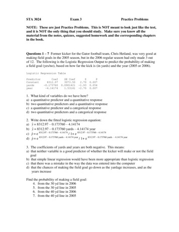
STEWART TECHNOLOGY ASSOCIATESSTA BOTSTAB2 – Technical NoteRev 1, August 27, 2008www.stewart-usa.com - USA and Caribbean2.0EXAMPLE SCREENSHOTSFigure 1 shows the case of a 48” pipeline with 20.6 mm wall thickness and a concrete weight coating, increasingthe OD to 58”STA BOTSTAB2: On-Bottom Stability of PipesDate of run:8/27/2008file name: BOTSTAB2:XLS Revised 08/10/08This software has been developed by: Stewart Technology Associates , Houston, Texas. Tel: (832) 472-2811; Fax: (713) 583-2058; info@stewart-usa.comVersion 2, Rev 1.1 - RP-F109 Computations still under Development. Revision Date: 08/27/08Run Ref:Indian Oiltanking Design and Engineering (IOTDE) Ltd.Print Page 1Print Page 2Print AllConditions &Second TrialSelectSeaBedSoilTypeShow GraphsPipe Info.:48" OD Oil Pipeline with Concrete Weight CoatingThis program determines the on-bottom stability of a submarine pipe in accordance with the Veritec Recommended Practice "On-Bottom Stability of Submarine Pipelines", October 1988.The program allows the user to input the design variables in the shaded cells. Using the data from the shaded cells the program calculates the velocities due to the current and waves.From the calculated velocity the lift, drag and inertia forces on the pipe are determined. The required weight for the pipe is displayed above the actual submerged weight of the pipewhich is supplied by the user. If the required weight of the pipe is larger than the actual submerged weight a warning is given cautioning the user of potential stability problems.User Defined Variables (in yellow shaded cells only)metric units below1.2192 m127.00 mm48.00 inPipe OD (Before Coating)5.00 inCoating Thicknessnormal flow regime0.01.4732 m58.00 inEffective Pipe OD (includes reduction for penetration)Penetration Switch31.00 m101.71 ftd, water depth1 ON, 0 OFF0.127 m5.00 in0.52 m/sec1.70 ft/sec2242 kg/m 3140.0 lbf/ft 3 Coating Density953.72 kgf/m640.69 lbf/ft Ws, submerged weight of pipe & contentsRef. current 1.01 knot1025 kg/m 364.00 lbf/ft 3 pw, mass density of waterdiameter range for stability info. on other pipesUr, reference current velocity at elevation zrzr, elevation above sea bed for ref. current5.00 m16.40 ft10.00 m32.81 ftHs, significant wave height0.900.903.00 hr3.00 hrSea state duration in hours1.201.20Cl, lift force coefficient (typical 0.90)Cd, drag coeff. (typ. 1.2 for sub-crit flow, 0.7 oscill.)13.00 sec13.00 secTp, spectral peak period of surface waves3.293.29Ci, inertial coeff. (typical 3.29)nonWave spreading (yes or no)0.700.70us, friction factor for soil (typical 0.7 for sand)0º3.30º3.35.41E 05soil type5.41E 054Show Graphsq º, Wave Direction (0º to 90º, 0º gives max)gamma, peakedness parameter ( 1.0 for PM)Tabulated Results - Using Veritec RP E305Print AllRe, Reynolds no. based on current and pipe diam.Select Sea Bed Soil Typemedium sandVariables Used to Calculate Velocity Due to Wave Motion and Due to Current, Separately and CombinedTn, sqrt(d/g), "natural period"Soil Properties in Accordance with Veritec RP E305 (medium sand)d50, mean grain sizeTn/Tp, ratio of natural/wave period0.50 mm0.020 in1.78 sec0.1371.78 sec0.1373.69 m0.0016.6129510.96 m/sec 20.3353998.9812.10 ft0.0016.6129513.15 ft/sec 20.3353998.98A0, orbital semi-diameter of particle velocity1.8827 m/s3.61 m/s0.950.141.211.8812.31 sec1.001.883 m/s28º195.30 kgf86.02 kgf6.18 ft/sec11.85 ft/sec0.950.141.211.8812.31 sec1.006.18 ft/sec28º430.63 lbf189.68 lbfUs*, significant water velocityU*, osc.vel.amp.single design oscillationTu/Tp, dependent on gamma and Tn/TpTn/Tukt, Eq.3.16, depends on gammaT*, period associated with a single design oscillationTu, zero-up-crossing periodR, wave direction & spreading reduc. fact.Us, sig. velocity due to wave motionphase angle in wave for max forcehorizontal forcelift forceKb, Nikuradse's equiv. sand roughness param.K, Keulegan Carpenter number UsTu/DA0/Kb, ratioAs, significant acceleration(Us*Tn)/Hs, dependent on gamma and Tn/Tpzr/Kb, ratio4.17E-05 m0.81119873106.083.63353290.694.17E-05 ft0.81119873106.083.63353290.69z0, bottom roughness parameter2.23E-010.42 m/s4.42E-03 m8771.91919.19 m4.620.690.36 m/s1.581888.6 kgf/m18527 N/m2.23E-011.38 ft/sec1.45E-02 ft8771.91962.96 ft4.620.691.17 ft/sec1.581269 lbf/ftM, current to wave velocity ratio UD/UsV (F109) UD (E305)z0a, apparent roughnesst, number of waves in the sea stateku, ratio between design single oscillation amplitude and spectral design vH*, maximum wave height in the sea stateK*, Keulegan Car.no. single design oscillation U*T*/DUD/Ur velocity reduc. factor for waves & currentUd, ave. veloc. over pipe from waves & currentFw, calibration factor, inc. safety factor of 1.1Required submerged weightWarning Pipe Not Stable!UD/Ur velocity reduction factor for steady currentzr/z0, ratioz0a/z0, ratio of apparent to bottom roughnessUS/Ur ratio of significant to reference velocityD/z0, ratio of pipe diameter to bottom roughnessUD/Ur velocity reduc. factor for waves & currentFIGURE 1 – Screenshot of Input (yellow Cells) and Results for Example Case.In Figure 1 the predicted weight for a stable pipe is 1269 lbf/ft, or 1888 kgf/m. The input pipe weight is 641lbf/ft. Hence the program warns that the pipe is not stable in this analysis. The significant wave height is 32.8feet and the water depth is 108 feet. A JONSWAP spectrum is used with gamma 3.3 and Tp 13 seconds. Nowave spreading has been specified and the wave direction is 0 degrees, which is perpendicular to the pipe. Acurrent velocity of 1 knot has been specified, perpendicular to the pipe at an elevation of 16.4 feet above theSTEWART TECHNOLOGY ASSOCIATES 1-832-472-2811 - public@stewart-usa.comM:\STAPROGS\STABOTSTAB\STA BOTSTAB Technical Note Rev1.docPage 4 of 16
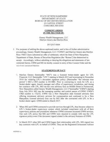
STEWART TECHNOLOGY ASSOCIATESSTA BOTSTAB2 – Technical NoteRev 1, August 27, 2008www.stewart-usa.com - USA and Caribbeansea bed. Lift, drag and inertia force coefficients have been specified in accordance with recommendations inE305. A friction coefficient is also given and the sea bed has been selected to be medium sand.Clean GraphsTabulated Results - Using DNV-RP-F109 Generalized Lateral Stability MethodShow GraphsThis Area is For Stability On Sand (RP-F109)272.8 kgf/m7000 N/m 31.6240.02670.039 m3.496E 00183.41 lbf/ft7.060E 006.474E 00L, significant weight parameter Ws/(0.5 rw D Us 2)Denom 0.5.rw.D.Us 2Lstable1/(2 M) 21925.2 kgf/mLstable21765.2 kgf/m1294 lbf/ft1186 lbf/ftRequired Stable Submerged Weight1Required Stable Submerged Weight23.456E 00L10 1000 waves942.4 kgf/m633 lbf/ftMinimum pipe weight required to limit the lateraldisplacement to 10 pipe diameters (1000 waves)2.253E 00L10 500 waves614.4 kgf/m413 lbf/ftMinimum pipe weight required to limit the lateraldisplacement to 10 pipe diameters (500 waves)0.015591.5845 lbf/cuft1.6250.02671.55 inN, spectral acceleration factor, Us/(g Tu)1926.1 kgf/m1295 lbf/ft Lstable1/(2 M) 2*Denomsg, pipe specific weight 1 (2/pi).(N.K.L)1.05 sg 3, method is OKg's Submerged unit soil weight. For sand normally in the range 7 000 (very loose) to 13 500 N/m 3 (very dense).ks initial, initial stiffness for penetration calculationzpi/D, initial penetration ratio34.89LstableInitial Penetration (User may wish to reduce the pipe diameter to account for the penetration)50 psf115 lbf/cuft0.09030.37720.04092.37 in0.29081.4211.87su, undrained shear strengthgs Submerged unit soil weight. For clay can be taken as 18 000 N/m 3G, clay soil strength parameterkc initial, initial stiffness for penetration calculationzpi/D, initial penetration ratioInitial Penetration (User may wish to reduce the pipe diameter to account for the penetration)F(M)0.137 C1L10/(2 M) 26.25 C2* On stiff clays this result may be conservative.Kb0.56 C37.776E 00Lstable12120.4 kgf/m1.424E 00L10388.2 kgf/mK 10, use Lstable1This Area is For Stability On Clay (RP-F109) and still needs testing2394 N/m 218000 N/m 30.09030.37700.04090.060 m0.29081425 lbf/ft * Required Stable Submerged Weight1*Minimum pipe weight required to limit the lateral261 lbf/ftdisplacement to 10 pipe diametersFIGURE 2 – Equivalent Results Using F109Figure 2 shows the results for the same input data, but using the generalized method from F109, and for thecase of a sand sea bed. In this case the pipe weight required for a stable pipe is 1294 lbf/ft, almost exactly thesame as in the E305 results. The weight required for an L10 pipe (that limits the lateral displacement to 10 pipediameters) is predicted to be just 633 lbf/ft.The results in Figure 2 for clay are provided with the caution that the clay calculations have not yet been fullytested.The following figures show screen captures of the dialog boxes that are displayed when the user clicks variousbuttons on the main screen.STEWART TECHNOLOGY ASSOCIATES 1-832-472-2811 - public@stewart-usa.comM:\STAPROGS\STABOTSTAB\STA BOTSTAB Technical Note Rev1.docPage 5 of 16
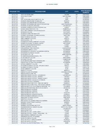
STEWART TECHNOLOGY ASSOCIATESwww.stewart-usa.com - USA and CaribbeanSTA BOTSTAB2 – Technical NoteRev 1, August 27, 2008Figure 3 – Dialog Box Enabling Selection of Sea Bed Soil Type.FIGURE 4 – Dialog Box to Select a Graph for Display and/or Printing.STEWART TECHNOLOGY ASSOCIATES 1-832-472-2811 - public@stewart-usa.comM:\STAPROGS\STABOTSTAB\STA BOTSTAB Technical Note Rev1.docPage 6 of 16
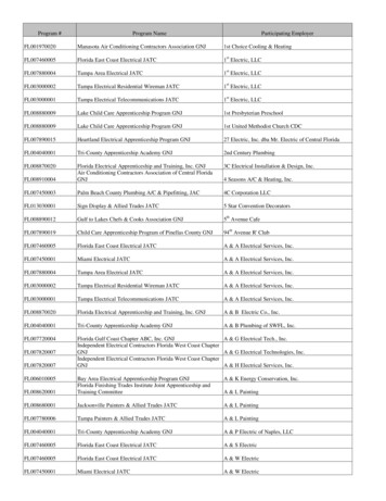
STEWART TECHNOLOGY ASSOCIATESSTA BOTSTAB2 – Technical NoteRev 1, August 27, 2008www.stewart-usa.com - USA and CaribbeanFIGURE 5STEWART TECHNOLOGY ASSOCIATES 1-832-472-2811 - public@stewart-usa.comM:\STAPROGS\STABOTSTAB\STA BOTSTAB Technical Note Rev1.docPage 7 of 16
STEWART TECHNOLOGY ASSOCIATESSTA BOTSTAB2 – Technical NoteRev 1, August 27, 2008www.stewart-usa.com - USA and CaribbeanFIGURE 6FIGURE 7STEWART TECHNOLOGY ASSOCIATES 1-832-472-2811 - public@stewart-usa.comM:\STAPROGS\STABOTSTAB\STA BOTSTAB Technical Note Rev1.docPage 8 of 16
STEWART TECHNOLOGY ASSOCIATESSTA BOTSTAB2 – Technical NoteRev 1, August 27, 2008www.stewart-usa.com - USA and CaribbeanFIGURE 8STEWART TECHNOLOGY ASSOCIATES 1-832-472-2811 - public@stewart-usa.comM:\STAPROGS\STABOTSTAB\STA BOTSTAB Technical Note Rev1.docPage 9 of
Tabulated Results - Using DNV-RP-F109 Generalized Lateral Stability Method This Area is For Stability On Sand (RP-F109) 3.496E 00 L, significant weight parameter Ws/(0.5 Uw D Us 2) K 10, use Lstable1 272.8 kgf/m 183.41 lbf/ft 7.060E 00 Lstable1/(2 M) 2 1925.2 kgf/m 1294 lbf/ft Required Stable Submerged Weight1 6.474E 00 Lstable2 1765.2 kgf/m 1186 lbf/ft Required Stable Submerged