Transcription
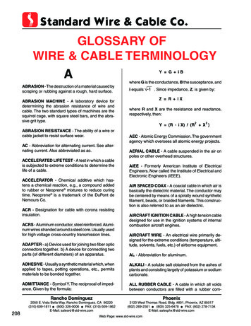
Bulletin 17800B-JCInstallation InstructionsRevision CHELIAX Coaxial CableCableTypeMaximumdiameterNominal over jacketdiameter in. (mm)FSJ11/4”0.29 (7.4)—0.045 (0.067) 1 (25)——LDF11/4”0.345 (8.8)—0.06 (0.09) 3 (76)——EFX23/8”0.45 (11.3)—0.09(0.13)——FSJ23/8”0.415 (10.5)—0.078 (0.12) 1 (25)——LDF23/8”0.44 (11.2)—0.08 (0.12) 3.75 (95)——FSJ41/2”0.52 (13.2)—0.14 (0.21) 1.25 (32)——HJ41/2”0.58 (14.7)0.25 (0.37)0.6863LDF41/2”0.63 (15.9)———HJ4.55/8”0.87 (22)0.40 (0.59)1.92178LDF4.55/8”0.87 (22)—0.27 (0.39) 8 (200)——HJ5 LDF57/8”1.10 (28)0.54 (0.8)0.33 (0.49) 10 (250)3.5325LDF61-1/4”1.55 (39.4)—0.66 (0.98) 15 (380)1.2*112*HJ7 LDF71-5/8”1.98 (50)1.04 (1.55)0.92 (1.36) 20 (510)141301HJ122-1/4”2.38 (60.4)1.16 (1.73)21.51997LDF122-1/4”2.35 (60)——Cable weight (lb/ft (kg/m)) MinimumFoamAirbend radiusdielectric in. (mm)dielectric——1.75 (45)5 (125)0.15 (0.22) 5 (125)——7 (180)22 (560)1.29 (1.91) 24 (610)Air dielectric volumeft³/liters/1000 ft1000 m*Foam dielectric cable that allows pressurization through inner conductor airNote: Air dielectric cable is supplied pressurized and includes an air inlet valve. Inner connectors, gaskets, silicone grease, connecting hardware, and installationinstructions are packed with unattached connectors. UHF style connectors do not include gaskets at the mating interface and may require sealing or weatherproofing.1. Inspecting and Preparing the CableInspect the cable for possible shipping damage.Andrew pressure-tests all air-dielectric cable andconnector assemblies at the factory; however, you shouldcheck them for possible pressure loss before installingthem. Use a tire pressure gauge to check the pressure atthe cable end. Connector assemblies are factorypressurized with dry air to 10 lb/in2 (70 kPa) prior toshipment.The maximum allowable pressure loss for air-dielectriccable assemblies is 1 lb/in2 (7 kPa) in 24 hours. If thisvalue is exceeded, check all joints for possible leaks,especially at pipe threads. Refer to Part 7 of this bulletinfor pressure information. If you cannot correct the leakycondition, contact the Andrew Customer Service (seepage 8) for assistance. Important: Do not install cablethat has excessive pressure loss.Notice: Verify the pressure-handling capability of allantenna system components before subjecting them tothe system operating pressure. Andrew HELIAX cablecan handle pressures up to 30 lb/in2 (207 Kpa); however,some antenna components may be damaged at suchhigh pressures.Factory-attached flange connectors have a blank flangeattached to them to maintain cable pressure duringshipment. The blank flange also protects the connectorface and prevents the entry of foreign matter. Do notremove this blank flange until after the cable is installed.Cover all cut cable ends that are not immediatelyterminated to protect them from the weather and the entryof foreign matter. Seal and repressurize air-dielectriccable cable to prevent moisture from developing insidethe cable. Use the cable end caps that were supplied withthe cable shipment to cover the cable ends.Before you hoist the cable, be sure to: Attach the connector at the antenna end of the cableusing the instructions supplied with the connector. Pressure-test the assembly and apply a weatherproofcovering for the assembly.1
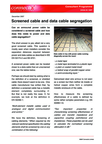
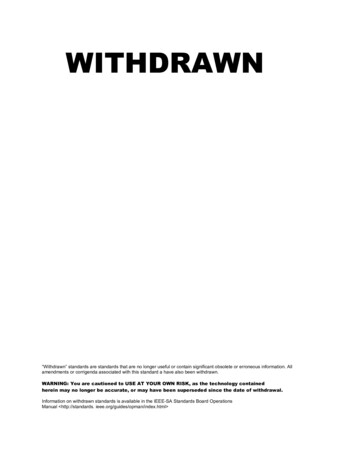
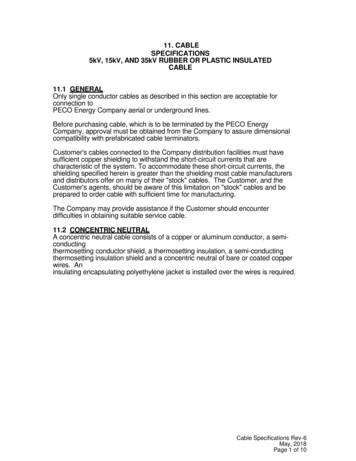
CrimpingtoolNOTICEWhen the standard hoisting grip iscompletely laced to the cable,attach a support clamp (purchasedseparately) or add six wraps oftwo-inch plastic tape along thebottom portion of the grip. Thisprevents the grip from relaxingbefore tension is applied.Clamping hoisting grip to cable withsupport clamp at heel of rGround wireattachmentRopetieCoaxialcableCable leaderbetween hoist gripand connector allowsfor connection toantenna when hoistgrip reaches pulley.Hoist lineto pulleysand rRopesafetylineDo not rely on the hoistinggrip alone. Always use anindependently attached ropesafety line when hoistingcable.ClevisThe safety line should be new(clean) and have a breakingstrength of at least ten timesthe cable weight, and shouldbe attached by a qualified andexperienced rigger.HoistinggripHangersTypical guy-wire supported towerCablereelHoist lineto nextgripGround nepulleyHoisting griprigging details
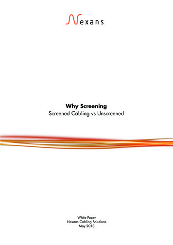
Note: Avoid using pressurizable components inunpressurized systems, such as air-dielectric feeds usedon antennas. Moisture can develop in these componentsand cause system performance problems.the special crimping tool. If the calculation demonstratesan insufficient length of leader cable, an additionalhoisting grip may be required lower on the cable beinghoisted.2. Hoisting the CableHoist Line. Use a hoist line that supports the total weightof the cable. Refer to the table for approximate cableweights per foot and per meter to calculate total cableweight.Pulleys. Use a strong pulley at both the top and bottomof the tower to guide the hoist line, as illustrated.BMonopoletowerA B CATop ofmeshCable Reel. Support the cable reel on an axle so that thereel can rotate freely as the cable is hoisted and the cableis pulled from the bottom. Have a crew member controlthe rotation of the reel.Short lengths of cable are shipped coiled and tied. Uncoilthese cables along the ground away from the towerbefore hoisting them.Standard and Support type Hoisting Grips. Hoistinggrips are interlaced wire that fit around the cable so thatthe looped handle at the upper end can be pulled tocause gripping of the cable. Grips are placed at intervalsof 200 ft (60 m) along the cable.CCablesupporthookInterior hook and support measurements that mustbe made before clamping down the hoisting gripJumpercableThe standard hoisting grip has open loops along itslength. The grip is first wrapped around the cable andthen the loops are laced together for hoisting. This typecan be wrapped over cable that has a connector installed.(A support clamp, available separately, is used to clampthe hoisting grip to the cable so that grip handle can beplaced on a support hook in a monopole tower.)WeatherproofedinterfaceGroundwiresThe support hoisting grip is designed to be compressedand slid onto the cut end of the cable before connectorattachment. When positioned at the desired location aftercable attachment, the heel of the grip is clamped to thecable with a support clamp (included). This is done sothat the grip can be used to support the cable from asupport hook in a monopole tower.Clamping Cable for Hoisting in Monopole Tower.Some calculations need to be made before clamping thehoisting grip to the cable so that it can be hoisted to asupport hook in a monopole tower. Three measurementsneed to be taken and added together.Top ofmeshAntenna feedercable exitSelf-supportingmonopole towerTop of monopole showingcables anchored to platformFirst, the distance from the top exit of the monopole to theinterior cable support hook should be measured, if notprovided by the manufacturer. This is much easier whendone on the ground before the tower is erected.Second, measure the distance from the top mesh of thehoisting grip to the top of the handle.Third, calculate the length of cable protruding from thetop exit of the monopole.These three distances added together give the distancefrom the top of the cable connector to the point where thetop of the hoisting grip’s mesh should be located afterattachment. When the location is found, the hoisting gripcan then be clamped down with the support clamp, usingCable run from monoplole to equipment building3
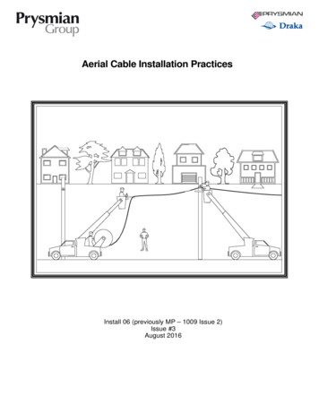
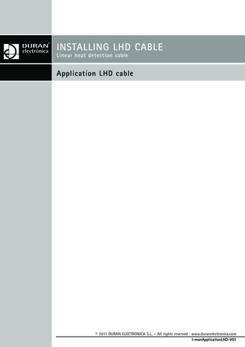
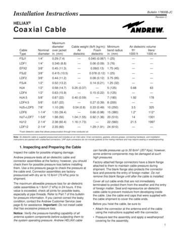
Hoisting Procedure. Place a weatherproof protectivecovering over the connector on the cable end to preventdamage during hoisting. Attach a hoisting grip near theend of the cable, allowing a sufficient length, called aleader, of at least 5 ft (1.5 m) to reach the antenna inputfrom the hoisted cable position. Tie the cable leader tothe hoist line so that it does not dangle during hoisting.When installing cable lengths more than 200 ft (60 m),add hoisting grips at intervals of 150 to 200 ft (45 to 60m). When additional grips are used, tie the cable to thehoist line between the grips with fiber-reinforced tape at50-ft (15-m) intervals. Make sure to allow slight slack inthe cable - not in the hoist line - between grips andmaintain that slack during hoisting. This slack in thecable indicates that the load is properly distributed.smaller, jumpers, or cable near the antenna), nyloncable ties may be used.Hoist the cable slowly and carefully. Prevent kinking byretarding rotation of the cable reel to control uncoiling ofthe cable. Avoid snags when hoisting or routing cablethrough and around tower members. Careless handlingcan cause kinks, dents, and scrapes in the cable.Note: Metal strapping or hose clamps should not beused to attach cable directly to the tower. This isbecause they can easily crush or otherwise damage thecable, or they may cause generation of electrical noisein the system.Carefully apply an even pressure when bending thecable. Do not make a cable bend smaller than theminimum bending radius given in the table. If routing isso confined that a smaller bend is required, use ajumper cable.3. Anchoring the CableAfter raising the cable to the correct height, anchor it tothe support structure, starting at the top.Cable attachment to tower lighting conduit is notrecommended because this may result in damage to theconduit. Such damage may cause water entry into theconduit and eventual lighting performance problems.All cable should be supported within 1 to 2 feet (30 to 61cm) of the antenna feed termination and of any cableconnector. Otherwise, cable hanger spacing should beas recommended in the hanger literature for the cabletype being installed. Allow enough cable at the antennaend to accommodate fine adjustments in antennaposition and to prevent strain at the antenna inputconnection. Maintain cable support with the hoist lineuntil anchoring is completed.Note: Connecting one cable hanger to another cablehanger for the purpose of anchoring one cable toanother cable over the vertical run is not recommended.Standard and snap-in types of cable hangers are usedfor anchoring 1/2-inch and larger cables. Insulatedhangers are required when cable is installed on a “hot”AM tower; that is, a tower used as an energy radiator.The entire length of cable should be inspected forpossible damage as it is being anchored. Dents ordeformations can cause degradation in electricalperformance. If the jacket has been cut, seal it with butyland vinyl tapes (Andrew Kit 221213 is recommended).When supporting the cable with standard or snap-inhangers is not possible (that is, cable sizes 1/2" and4Standard hangerSnap-in hanger4. GroundingGrounding Cable. The top and bottom of the cableattached to the tower should be electrically grounded tothe tower with Andrew grounding kits for lightningprotection. The antenna input connection cannot serveas the top ground point. Also, ground the vertical cablerun at midpoint if its height on the tower is greater than200 feet (61 m).Local building codes should be followed,which may require grounding the cable outside, near thewall of the equipment building. The cable should also begrounded near the wall inside the building (per NECArticle 810-55 and 820-33 grounding requirements).Surge Protectors. Surge protectors capable ofwithstanding multiple lightning strikes may be installedat the end of the cable that enters the equipmentbuilding. The surge protector is fitted to the cable endand includes a bulkhead connector interface thatmounts to a ground plate with a washer and nut.Grounding to Earth. Grounding should be continuedfrom the tower and equipment building to aninterconnected grounding system in the earth. Such asystem generally consists of a group of buried groundrods welded to an underground loop of wire.
Bulkheadmounting nutBulkheadconnectorinterfaceCableiceshieldQuarter waveshorting stubAPTL surge protectors fitted to foam coaxial cablesGround wireattachmentto cableTowerground wiresto earthGround wireattachment totower memberGround wire attachment of vertical cable runTower ground wire attachmentand view of cable ice shieldEquipmentbuildingGround wire attachmentof horizontal cable pper barground wireto earth5
5. Horizontal Cable RunsStandardcable entrybootsThe cable may be routed horizontally from the base ofthe tower to the equipment building either above orbelow ground.Above-ground Cable. Attach the above-ground cableto the horizontal support member, such as a cablebridge, with the same type hangers and spacings usedin the vertical run. Exposed horizontal runs must beprotected from the weight of accumulated ice anddamage from falling ice or other objects by means of anice shield.Wall or Roof Feed-thru Ports. HELIAX feed-thruports are recommended when a cable must passthrough a roof or wall of a building. Single ports orpanels which contain groups of ports are available.TheArrestorPort II Integrated Cable Entry/Ground Systemis a panel with ports and a ground plate toaccommodate the mounting of surge protectors.Buried Cable. Buried cable should be located below thefrost line (depth) of the area and at least 3 ft (1 m). Thiswill protect the cable from damage by heavy vehicles.Surround the cable with a 4-inch (102-mm) layer of sandto protect the jacket from stones or other sharp objects.Place location markers at convenient intervals overburied cables, especially at the locations of cablesplices.GroundplateGround wirefrom cableSurgeprotectorsGround wires connectfrom both ends ofground plate to earthArrestorPort II integrated cable entryand ground system with APTL bulkheadsurge protectors installed Make sure that if an inner stub is used, it is screwedinto a corrugated inner conductor so that its end isflush with the conductor. Use only the wrench sizes given in the instructions.6. Cable ConnectionsConnector Instructions. Step-b
antenna system components before subjecting them to the system operating pressure. Andrew HELIAX cable can handle pressures up to 30 lb/in2 (207 Kpa); however, some antenna components may be damaged at such high pressures. Factory-attached flange connectors have a blank flange attached to them to maintain cable pressure during shipment. The blank flange also protects the connector face