Transcription
UM10966NTAG I²C plus Explorer Kit - Android DemoRev. 2.2 — 20 May 2020360122User manualCOMPANY PUBLICDocument informationInfoContentKeywordsNTAG I2C plus, Explorer Kit, Android, NFC tagAbstractThis User manual describes the functionalities and how to use theAndroid and PC application of the NTAG I2C plus Explorer kit. Bothapplications provide the same functionality and have the same look andfeel so this User manual is valid for both.SECURITYSTATUS
UM10966NXP SemiconductorsNTAG I²C plus Explorer Kit - Android DemoRevision historyRevDateDescription2.220200520Section 5: FCC statement chapter extended2.120170309Update - Bluetooth Pairing added2.020170201Updates1.020160216Initial VersionSECURITYSTATUSContact informationFor more information, please visit: http://www.nxp.comUM10966User manualCOMPANY PUBLICAll information provided in this document is subject to legal disclaimers.Rev. 2.2 — 20 May 2020360122 NXP B.V. 2020. All rights reserved.2 of 58
UM10966NXP SemiconductorsNTAG I²C plus Explorer Kit - Android Demo1. ObjectNTAG I2C plus Explorer kit is an all-in-one demonstration and development resource todemonstrate the unique properties of the NTAG I2C plus connected tag. By including afull complement of hardware and software tools, users can investigate the capabilities ofthe chip through the various demonstrations, develop and test their own applications(with additional LPC-Link2 debug probe1).This User Manual explains how to use the NTAG I2C plus demo application for Android.The Windows app is not detailed in this User Manual since it provides identicalfunctionalities as the Android app, therefore the same User Manual is valid.Technical aspects related to the IC features are beyond the scope of this document. Toget further technical details please consult the dedicated Datasheet “NTAG I2C plus, NFCForum Type 2 Tag compliant IC with I2C interface” (refer to [NTAGI2Cplus]).SECURITYSTATUS1UM10966User manualCOMPANY PUBLICwww.nxp.com/LPC-LINK2All information provided in this document is subject to legal disclaimers.Rev. 2.2 — 20 May 2020360122 NXP B.V. 2020. All rights reserved.3 of 58
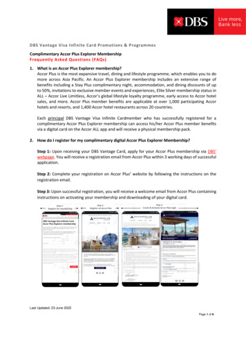
UM10966NXP SemiconductorsNTAG I²C plus Explorer Kit - Android Demo2. NTAG I2C plus introductionThe NTAG I2C plus part of NXP’s NTAG family offering both contactless and contactinterfaces. In addition to the passive NFC Forum compliant RF interface, the NTAG I2Cplus provides an I2C interface that allows the IC to communicate with the microcontrollerwhen the chip is powered by an external device, i.e. a NFC mobile phone.The NTAG I2C plus operating in energy harvesting mode provides the possibility tosupply external low power devices (e.g. microcontrollers) with the energy generated fromthe RF field of the external NFC device.SECURITYSTATUSFig 1.NTAG I2C plusThe NTAG I2C plus product has two types of memories:1. EEPROM memory compliant with the NFC Forum Type 2 Tag implementation.2. 64-byte SRAM memory, which is mapped to the EEPROM memory and it isexternally powered.The NTAG I2C plus features a pass-through mode that allows fast download and uploadof data from the RF interface to the I2C interface and vice versa. This functionality makesuse of the SRAM memory that allows fast data transfer between interfaces without theEEPROM performance limitations.In addition to the I2C interface functionality, the NTAG I2C plus product features an EventDetection pin for waking up the connected host devices or synchronizing the datatransfer between the two interfaces.The NTAG I2C plus offers the possibility to protect the memory access. This protection isdone by authenticating the tag with a password. When the tag is protected,authentication is needed to access the memory. The NTAG I2C plus also improves thespeed when writing into the SRAM memory.UM10966User manualCOMPANY PUBLICAll information provided in this document is subject to legal disclaimers.Rev. 2.2 — 20 May 2020360122 NXP B.V. 2020. All rights reserved.4 of 58
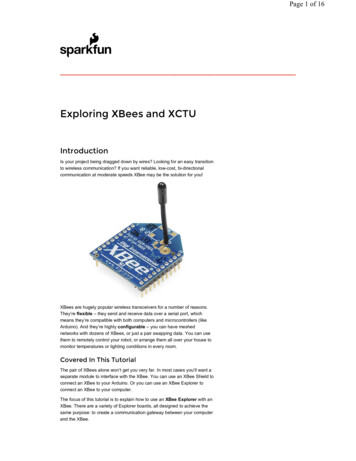
UM10966NXP SemiconductorsNTAG I²C plus Explorer Kit - Android Demo3. NTAG I2C plus Explorer kit contentsThe NTAG I2C plus Explorer kit (NEK) consists of hardware and software tools thatdevelopers can use to understand the NXP NTAG I2C plus functionalities and create firstprototypes to demonstrate its potential for other application. The kit includes:3.1 Hardware components3.1.1 NTAG I2C plus Explorer boardA hardware board based on the NXP LPC 11U24 microcontroller (refer to [LPC11U24]),with on-board LCD display, NXP LM75B temperature sensor (refer to [LM75B]), voltagemonitors, I2C serial bus connector, JTAG/SWD debug connector, RGD LED micro USBconnector and five push buttons.SECURITYSTATUSFig 2.UM10966User manualCOMPANY PUBLICNTAG I2C plus Explorer Board (refer to [EXPLORER])All information provided in this document is subject to legal disclaimers.Rev. 2.2 — 20 May 2020360122 NXP B.V. 2020. All rights reserved.5 of 58
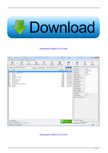
UM10966NXP SemiconductorsNTAG I²C plus Explorer Kit - Android Demo3.1.2 Antenna boardThe antenna board carries the NTAG I2C plus 2k version itself and provides twointerfaces: The RF interface to an NFC device. The I2C interface to the host, e.g. the NTAG I2C plus Explorer board.The design files for both the PCB and Flex antenna can be found on the web page (referto [PCB Antenna] and [Flex Antenna]SECURITYSTATUSFig 3.PCB and Flex antenna boards with NTAG I²C plus IC3.1.3 Field detector boardThe position of the antenna of NFC devices vary from device to device. To use theExplorer Kit with an NFC Device, NFC radio needs to be enabled. To find the position ofthe antenna, it is convenient to use the included field detector board. The LED helps tofind the antenna position.Design files may be downloaded from the demo board homepage (refer to [FieldDetector])Fig 4.UM10966User manualCOMPANY PUBLICField detector boardAll information provided in this document is subject to legal disclaimers.Rev. 2.2 — 20 May 2020360122 NXP B.V. 2020. All rights reserved.6 of 58
UM10966NXP SemiconductorsNTAG I²C plus Explorer Kit - Android Demo3.1.4 USB readerInstead of a NFC device, the USB (PCSC) reader (Identiv uTrust CLOUD 3700F) may beused in combination with the Windows app to develop applications.Fig 5.Identiv uTrust CLOUD 3700F readerTo install the reader, download latest driver from the web page (refer to [Identiv]), extract“Identiv uTrust Installer.zip” and install it with no reader connected.In Windows 7 operative systems, when a smartcard is placed over the reader there isfrequently an issue regarding the smartcard mini-drivers. Although a solution to thisproblem is given in this section, more information can be found on the Windows SupportWebpage2. To solve this issue the Smart Card Plug has to be disabled and Play in localGroup Policy has to be changed to primary group policy settings for smart cards. Theprocedure is as follows:SECURITYSTATUS1. Click Start, type gpedit.msc in the Search programs and files box, and thenpress ENTER.2. In the console tree under Computer Configuration, click AdministrativeTemplates.3. In the details pane, double-click Windows Components, and then doubleclick Smart Card.4. Right-click Turn on Smart Card Plug and Play service, and then click Edit.5. Click Disabled, and then click OK.6. Click Start, type regedit.exe in the Search programs and files box, and thenpress ENTER.7. Go through the tree key, on the left, up to the key HKEY LOCAL MACHINE \ Software \ Microsoft \ Cryptography \Calais for 32-bit system or HKEY LOCAL MACHINE \ SOFTWARE \ Wow6432Node \ Microsoft \Cryptography \ Calais for 64-bit system8. Add a new DWORD value named CardDisconnectPowerDownDelay and set itsvalue to 0.9. Click Start, type services.msc in the Search programs and files box, and thenpress ENTER.10. Find the smart card service in the list, right-click and click Restart.11. Now you may plug the reader2UM10966User manualCOMPANY 2.All information provided in this document is subject to legal disclaimers.Rev. 2.2 — 20 May 2020360122 NXP B.V. 2020. All rights reserved.7 of 58
UM10966NXP SemiconductorsNTAG I²C plus Explorer Kit - Android Demo3.1.4.1USB Reader firmware updateIn some cases, reader is not functioning properly with Windows “NTAG I²C plus Demo”application. This is due to newer Reader s firmware. In this case, it needs to be updated,using patch tool3.3.2 Software components3.2.1 NTAG I2C plus Explorer board firmwareThe firmware runs on the NTAG I2C plus Explorer board and is flashed during productionat the MCU which supports the demonstration functionality of the hardware. Thedelivered NTAG I2C plus Explorer board firmware consists of three applications: NTAG I2C Explorer Bootloader: This project implements the secondarybootloader application. It is flashed at on-chip memory address starting at0x0000 0000 and it is the first application to be executed after the MCU boots.This application has three functions:o Jump to the start memory of the user application.o Enter into flashing mode functionality.o Enter into USB mode (Peek and Poke).SECURITYSTATUS NTAG I2C Explorer Demo: This project implements the logic supporting theAndroid / Windows demonstration applications. It is flashed at on-chip flashmemory starting at 0x0000 4000 address and it is executed after the bootloaderjumps to the application start address. NTAG I2C Explorer Blink: This is a sample project that sets into blinking modethe NTAG I2C Explorer board as soon as the RF field is detected. Thisapplication is provided to illustrate the NFC flashing functionality and its binaryimage is provided embedded by default into the Android app (see Section 4.5).3.2.2 Android appThe demo application on an Android NFC phone (“NFC mobile”) showcasing the variousfeatures of the NTAG I2C plus. The NTAG I2C Demo application is available for downloadfrom the public NXP website as well as at Google Play.3UM10966User manualCOMPANY t/SW4044.zipAll information provided in this document is subject to legal disclaimers.Rev. 2.2 — 20 May 2020360122 NXP B.V. 2020. All rights reserved.8 of 58
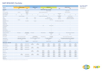
UM10966NXP SemiconductorsNTAG I²C plus Explorer Kit - Android DemoFig 6.Android app GUINote: The UM10989 (refer to [UM10989]) describes in detail how to get started with thedevelopment of Android Applications.SECURITYSTATUS3.2.3 Windows appTogether with the USB reader, the Windows app can be utilized to substitute a missingNFC mobile phone. The Windows app has similar functionalities as the Android app. Thissoftware component is available as a download from the public NXP website. Thesoftware will include a setup file which will install the Windows App in the folder ‘Programfiles/NXP Semiconductors’, this installation process will create a shortcut to the WindowsApp on your desktop. No further procedure is required to run this application.1. Download the NTAG I2C Demo App (refer to [PC App])2. If not done, install the Identiv uTrust driver as described above and the NTAG I2CDemo App3. Launch the NTAG I2C Demo AppThere are some points to consider when using the Windows App, since it is connected toan external reader via USB. There are sometimes issues with the connection betweenthe reader and the tag. On these cases, it is recommended to restart the app and re-plugthe reader.UM10966User manualCOMPANY PUBLICAll information provided in this document is subject to legal disclaimers.Rev. 2.2 — 20 May 2020360122 NXP B.V. 2020. All rights reserved.9 of 58
UM10966NXP SemiconductorsNTAG I²C plus Explorer Kit - Android DemoSECURITYSTATUSFig 7.Windows application GUINote: The Windows application functionalities, GUI and look and feel are intentionallymade the same as the Android application. The Windows application is intended to run ina Windows environment together with the Identiv uTrust CLOUD 3700F reader as asubstitute in case an NFC phone is not available. Therefore, this User Manual is valid forboth the Android app and Windows application. However, only Android app screenshotsare shown in this document.3.2.4 Peek and Poke GUIThe Peek and Poke GUI is a Windows app that can be used to examine the detailedmemory contents of the NTAG I2C plus EEPROM via I2C interface. From hardware pointof view only a USB cable connection from the board to the PC is needed (no need of theUSB NFC reader). This software component is available as a download from the publicNXP website (refer to [Peek&Poke]).UM10966User manualCOMPANY PUBLICAll information provided in this document is subject to legal disclaimers.Rev. 2.2 — 20 May 2020360122 NXP B.V. 2020. All rights reserved.10 of 58
UM10966NXP SemiconductorsNTAG I²C plus Explorer Kit - Android DemoFig 8.Peek and Poke GUINote: The UM10967 (refer to [UM10967]) describes in detail how to get started with thePeek and Poke tool and the different functionalities it offers.SECURITYSTATUSUM10966User manualCOMPANY PUBLICAll information provided in this document is subject to legal disclaimers.Rev. 2.2 — 20 May 2020360122 NXP B.V. 2020. All rights reserved.11 of 58
UM10966NXP SemiconductorsNTAG I²C plus Explorer Kit - Android Demo4. NTAG I2C plus Explorer Demo appThe Android application is intended to operate on devices running Android version 4.0and above. The application has been optimized for a correct visioning of the graphicalelements in smartphones featuring different resolutions.As seen in Fig 9, the Android application consists of two demos that can be launchedfrom the main activity of the application and four configuration functionalities that areaccessed from the configuration selection view in the main activity.SECURITYSTATUSFig 9.Application overview4.1 Demo tabAfter the Splash window closes, the Demo tab will appear. This screen allows the user tolaunch the Demo tab itself, the NDEF demo tab, the Speed demo tab and access theConfiguration tab, with all configuration functionalities supported by the application.Regarding the Demo tab, it allows demonstrating: The Energy harvesting functionality of the NTAG I2C plus that enables thepowering up of the complete demo kit board with the energy harvested from theRF interface without any battery. The RF to I2C communication enabling us to modify the LED color by pressing therelated color button on the NFC device screen. The I2C to RF communication as the set of push buttons pressed by the user onthe demo kit board reflected on the NFC device screen. The dynamic bidirectional communication between the two interfaces as thetemperature value as well as the voltage on the energy-harvesting pin getdynamically updated on both the low power screen and the NFC device screen.UM10966User manualCOMPANY PUBLICAll information provided in this document is subject to legal disclaimers.Rev. 2.2 — 20 May 2020360122 NXP B.V. 2020. All rights reserved.12 of 58
UM10966NXP SemiconductorsNTAG I²C plus Explorer Kit - Android DemoSECURITYSTATUSFig 10. Demo tab snapshotUM10966User manualCOMPANY PUBLICAll information provided in this document is subject to legal disclaimers.Rev. 2.2 — 20 May 2020360122 NXP B.V. 2020. All rights reserved.13 of 58
UM10966NXP SemiconductorsNTAG I²C plus Explorer Kit - Android Demo4.1.1 Configuring NEK board to demonstrate RF to I2C communicationThe board configuration part of the demonstration shows how the NTAG I2C plus passesa command from the RF input through the SRAM and I2C serial interface output to themicroprocessor, which acts upon the command and lights the appropriate LED.1. Touch one of the colored board configuration buttons on your mobile device. TheNTAG icon then changes color, indicating the color selection.2. Tap your mobile device on the antenna. When properly placed, the LED willilluminate in the chosen color. Optionally, the LCD display will display theharvested voltage, the temperature sensed by the board, the default text or thestored NDEF message if the corresponding options are enabled in the boardconfiguration menu.SECURITYSTATUSFig 11. Green LED board configuration selectionUM10966User manualCOMPANY PUBLICAll information provided in this document is subject to legal disclaimers.Rev. 2.2 — 20 May 2020360122 NXP B.V. 2020. All rights reserved.14 of 58
UM10966NXP SemiconductorsNTAG I²C plus Explorer Kit - Android Demo4.1.2 Reading board input to demonstrate I2C to RF communicationThe three colored buttons on the NEK board demonstrate information from the boardbeings transferred from the microprocessor through the I 2C serial bus to the NTAG I2Cplus, which then sends it via the RF field to the mobile device for display. When pressed,each colored button on the NEK board will cause a corresponding shade off on the boardinput NXP logo.SECURITYSTATUSFig 12. Reading board inputUM10966User manualCOMPANY PUBLICAll information provided in this document is subject to legal disclaimers.Rev. 2.2 — 20 May 2020360122 NXP B.V. 2020. All rights reserved.15 of 58
UM10966NXP SemiconductorsNTAG I²C plus Explorer Kit - Android Demo4.1.3 Temperature sensorThe NEK board incorporates a temperature sensor for measuring the ambienttemperature. This information can be shown in the Demo tab of the Android/PCapplication. Additionally it can be shown in the LCD display if the option is checked in themenu.This operation demonstrates the NTAG I2C plus operating in pass-through mode, inwhich data passes through its SRAM. It is also another demonstration of passing datafrom the microprocessor through the I2C serial bus to the NTAG I2C plus, which can beread through the RF interface for display on the mobile device.SECURITYSTATUSFig 13. Temperature sensor demonstrates SRAM pass through modeUM10966User manualCOMPANY PUBLICAll information provided in this document is subject to legal disclaimers.Rev. 2.2 — 20 May 2020360122 NXP B.V. 2020. All rights reserved.16 of 58
UM10966NXP SemiconductorsNTAG I²C plus Explorer Kit - Android Demo4.1.4 Enabling LCD displayYou can enable the NEK board LCD by touching the Enable LCD selection box. Whendoing so, the LCD will show the predefined NTAG I2C plus Explorer text message, theenergy harvested and, if enabled, the temperature sensed by the board in Celsius andFahrenheit degrees.Once again, this operation demonstrates the NTAG I2C plus chip operating in passthrough mode sends a command from the RF input through the I2C serial interface outputto the microprocessor, which in turn acts upon the command and turns on the LCDdisplay.SECURITYSTATUSFig 14. Enabling NEK board LCDUM10966User manualCOMPANY PUBLICAll information provided in this document is subject to legal disclaimers.Rev. 2.2 — 20 May 2020360122 NXP B.V. 2020. All rights reserved.17 of 58
UM10966NXP SemiconductorsNTAG I²C plus Explorer Kit - Android Demo4.1.5 Displaying NDEF text message on the NEK board LCDYou can display the NDEF text message on the NEK board LCD by touching the DisplayNDEF message on LCD selection box.Again, this operation demonstrates the NTAG I2C plus operating in pass-through mode.First, the NDEF message is read from the NTAG I2C plus EEPROM memory and istransferred to the MCU using the SRAM memory, which displays it in the display.SECURITYSTATUSFig 15. Displaying NDEF text message on NEK board LCDUM10966User manualCOMPANY PUBLICAll information provided in this document is subject to legal disclaimers.Rev. 2.2 — 20 May 2020360122 NXP B.V. 2020. All rights reserved.18 of 58
UM10966NXP SemiconductorsNTAG I²C plus Explorer Kit - Android Demo4.2 NDEF tabThe NDEF tab allows the user to read or write an NDEF message to the NTAG I2C plusEEPROM. Actually, it could be used to read or write an NDEF message to any NFCForum Type 2 Tag, such as a MIFARE Ultralight, NTAG21x, .On the Read NDEF mode, the application reads the NDEF message TLV from the NTAGI2C plus and returns its content and the type of NDEF message.On the Write NDEF mode, the application allows the user to write a Text type, URI type,Bluetooth pairing type or Smart Poster NDEF message. Text record type is used to store plain text data. URI record type allows NFC tags to trigger actions on the NFC device (usually thesmartphone), such as opening a webpage or sending an SMS message. Bluetooth pairing NDEF messages contain information about a Bluetooth devicethat allows the smartphone to pair with that Bluetooth device by just tapping thetag. In the case of writing a Bluetooth pairing type message, it is important toremember that the MAC address shall be 6 bytes, in hexadecimal (therefore, 12characters from 0 to F). Smart Poster record type defines a structure including a URI record type and aText record type as building blocks.SECURITYSTATUSThe NDEF tab also contains a Write default NDEF message button. When this button ispressed, the application automatically writes a NDEF Smart Poster message with the 2records (optionally 3): Text record “NTAG I2C plus EXPLORER” URI content: www.nxp.com/demoboard/OM5569. Optionally: AAR (Android Application Record)More on Write default NDEF message is described below in section 4.2.2.UM10966User manualCOMPANY PUBLICAll information provided in this document is subject to legal disclaimers.Rev. 2.2 — 20 May 2020360122 NXP B.V. 2020. All rights reserved.19 of 58
UM10966NXP SemiconductorsNTAG I²C plus Explorer Kit - Android DemoSECURITYSTATUSFig 16. NDEF tab snapshotWhen the NDEF message has been successfully written the “write tag successfully done”popup appears temporarily in the application informing the user that the message hasbeen correctly written. There is no need to tap the tag again if you want to write multipleNDEF messages and read them in between.In order to learn more about the different types of NDEF messages and what structurethey have, please refer to the following NFC Forum specifications:“NFC Data Exchange Format (NDEF) Technical Specifications”“NFC Record Type Definition (RTD) Technical Specification”“NFC Text RTD Technical Specification”“NFC URI RTD Technical Specification”“NFC Forum Connection Handover Technical Specification”“NFC Smart Poster RTD Technical Specification”“Bluetooth Secure Simple Pairing Using NFC”UM10966User manualCOMPANY PUBLICAll information provided in this document is subject to legal disclaimers.Rev. 2.2 — 20 May 2020360122 NXP B.V. 2020. All rights reserved.20 of 58
UM10966NXP SemiconductorsNTAG I²C plus Explorer Kit - Android Demo4.2.1 Reading NDEF dataTo read a NDEF message out of NTAG I2C plus:1. Select Read NDEF from the tab on the right of the mobile device screen.2. Tap the mobile device onto the antenna.3. A proper read will result in a message on the mobile device indicating Read tagsuccessfully done. If no NDEF message is found or NTAG I²C plus is notformatted as defined in NFC Forum Type 2 Tag spec, it will result in a messageNTAG I2C plus product is not NDEF formatted. Additionally, the Enable NDEFread loop selection box can be used to set the application to permanently readthe EEPROM memory, so any change will automatically appear in the window.SECURITYSTATUSFig 17. Reading NDEF message stored in EEPROM of NTAG I2C plusUM10966User manualCOMPANY PUBLICAll information provided in this document is subject to legal disclaimers.Rev. 2.2 — 20 May 2020360122 NXP B.V. 2020. All rights reserved.21 of 58
UM10966NXP SemiconductorsNTAG I²C plus Explorer Kit - Android Demo4.2.2 Writing NDEF dataTo write an NDEF message into the NTAG I2C plus:1. Select Write NDEF from the tab on the right of the mobile device screen.2. Type a message into the NDEF message area. Or alternatively, press WriteDefault NDEF message on your screen, which writes a NDEF Smart Postermessage with the text content: “NTAG I2C plus EXPLORER” and the URIcontent: www.nxp.com/demoboard/OM5569. Additionally, you can add to yourNDEF message an Android Application Record (AAR), which adds the packagename of the NTAG I2C plus Demo application embedded inside the NDEFrecord. You can add an AAR to any NDEF record of your NDEF messagebecause Android searches the entire NDEF message for AARs. If it finds anAAR, it starts the application based on the package name inside the AAR. If theapplication is not present on the device, Google Play is launched to downloadthe application.3. Tap the mobile device onto the antenna.4. A proper write will result in a message on the mobile device indicating write tagsuccessfully done.SECURITYSTATUSFig 18. Writing NDEF message to NTAG I2C plus EEPROMUM10966User manualCOMPANY PUBLICAll information provided in this document is subject to legal disclaimers.Rev. 2.2 — 20 May 2020360122 NXP B.V. 2020. All rights reserved.22 of 58
UM10966NXP SemiconductorsNTAG I²C plus Explorer Kit - Android Demo4.3 Speed tabThe speed Test Demo measures the transfer bit rate when communicating with theNTAG I2C plus Explorer board according to different configurations.4.3.1 SRAM speed testThe SRAM speed Test measures the speed at which the data is transferred from theapplication to the microcontroller through the SRAM (with the NTAG I2C plus in passthrough mode), and vice versa. First, the application writes data to the SRAM severaltimes, and the microcontroller reads from it. This way, the throughput of thecommunication in pass-through mode from the application to the microcontroller can beobtained. Once this first test has finished, the microcontroller starts writing to the SRAMmemory, while the application reads from it. This way, the throughput from themicrocontroller to the application can be measured.SECURITYSTATUSFig 19. Data transfer speed measurement concept behind the SRAM selectionSince the size of the SRAM memory is 64 bytes, the data to be transmitted and receivedhas to be a multiple of 64. Actually, what is transmitted is the number of 64-byte blocksdefined by the user in the Block multiplier field (10 by default).The integrity of the data transferred in both directions is checked by appending a CRC32value in the last block. The CRC32 is calculated for the whole message that has beentransferred (for all the blocks). If the CRC32 from the message received by theapplication is right, it will show an “Integrity of the data: OK” message. On the other hand,if the CRC32 from the message received by the board is right, it will turn on the greenLED at the end of the Speed Test.Once the test has been finished, both the application and the microcontroller indicatewhether the integrity check was successful (through a green LED at the microcontroller),and the application shows the time, mean speed and data transferred for both directions.UM10966User manualCOMPANY PUBLICAll information provided in this document is subject to legal disclaimers.Rev. 2.2 — 20 May 2020360122 NXP B.V. 2020. All rights reserved.23 of 58
UM10966NXP SemiconductorsNTAG I²C plus Explorer Kit - Android DemoSECURITYSTATUSFig 20. SRAM Speed test snapshotUM10966User manualCOMPANY PUBLICAll information provided in this document is subject to legal disclaimers.Rev. 2.2 — 20 May 2020360122 NXP B.V. 2020. All rights reserved.24 of 58
UM10966NXP SemiconductorsNTAG I²C plus Explorer Kit - Android Demo4.3.2 EEPROM speed testThe EEPROM Speed Test measures the speed at which the application is able to writeand read the EEPROM memory of the NTAG I2C plus. In order to do this, an NDEFmessage is written to the EEPROM, and then, the same NDEF message is read. Thewritten NDEF message is a text type message that contains the data in the textbox of theapplication repeated as many times as indicated in the Block multiplier field.First, the application creates the NDEF message to be written by creating a string thatcontains the content from the textbox as many times as indicated, and adding theappropriate header. Then, it writes it to the EEPROM memory by sending as many NFCForum Type 2 Tag Write commands as necessary, and measuring the time it takes to doso. Once it has finished writing, it reads the NDEF message from the NTAG I2C plusEEPROM memory.Once the test is finished, the application shows the number of bytes, mean speed andtime for both the reading and writing process. The user can also check the content of thememory to ensure that the NDEF message has been written appropriately.SECURITYSTATUSFig 21. EEPROM Speed test snapshotComparison between EEPROM read/write Fig 21 and SRAM read/write Fig 20 isrepresented. Performing operations on SRAM memory with FAST READ andFAST WRITE commands, highly improve overall communication speed.UM10966User manualCOMPANY PUBLICAll information provided in this document is subject to legal disclaimers.Rev. 2.2 — 20 May 2020360122 NXP B.V. 2020. All rights reserved.25 of 58
UM10966NXP SemiconductorsNTAG I²C plus Explorer Kit - Android Demo4.4 Configuration tabThis tab shows a selection menu that provides access to the different configurationactivities of the NTAG I2C plus supported by the application. From this screen, the usermay select Read Tag Memory, Reset Tag Memory, Read Session Registers orRead/Write Configuration registers.SECURITYSTATUSFig 22. CONFIG tab menuUM10966User manualCOMPANY PUBLICAll information provided in this document is subject to legal disclaimers.Rev. 2.2 — 20 May 2020360122 NXP B.V. 2020. All rights reserved.26 of 58
UM10966NXP SemiconductorsNTAG I²C plus Explorer Kit - Android Demo4.4.1 Reading tag memoryThis option reads and displays on the screen the content of the whole memory of theNTAG I2C plus product. The complete content can be scrolled on the screen. To read thetag memory:1. Select Read Tag Memory from the Configuration tab.2. Tap the mobile device to the antenna (it might take 2-3 seconds to read thememory content.3. The screen will display the entire memory contents.For security reasons, the pages from 0xE2 to 0xFF in the sector 0 are hidden whenreading all the memory. These bytes define the PWD, PACK, AUTH0, PT I2C andACCESS bytes.SECURITYSTATUSFig 23. Read tag memory snapshotUM10966User manualCOMPANY PUBLICAll information provided in this docu
Fig 6. Android app GUI Note: The UM10989 (refer to [UM10989]) describes in detail how to get started with the development of Android Applications. 3.2.3 Windows app Together with the USB reader, the Windows app can be utilized to substitute a missing NFC mobile phone. The Windows app has similar functionalities as the Android app. This